Challenges and Emerging Trends in Hydrogen Energy Industrialization: From Hydrogen Evolution Reaction to Storage, Transportation, and Utilization
Abstract
Green hydrogen (H2) emerges as a sustainable alternative to fossil fuels, offering a clean method to store renewable energy through water electrolysis with high energy content and zero carbon emissions. While research largely focuses on specific aspects such as hydrogen evolution reaction (HER), seawater HER electrocatalysts, and electrolyzer development, these studies often overlook the broader hydrogen economy from an integrated industry chain perspective. This review bridges that gap by providing a comprehensive analysis of hydrogen energy industrialization, covering advancements in HER, seawater HER, and electrolyzers, all aim at enabling industrial-scale H2 production. It further explores innovations and challenges in hydrogen storage and transportation, as well as real-world projects spanning the green hydrogen supply chain. Additionally, life cycle assessment studies validate the environmental benefits of using renewable energy sources for green H2 production. Furthermore, this review highlights advancements in counter-oxygen evolution reactions and organic oxidation reactions, alongside strategies to mitigate competing chlorine evolution reactions. Through this comprehensive examination, this review aims to inform readers of the latest developments in hydrogen energy industrialization, explore its growth potential, and provide new insights to propel the hydrogen economy forward.
1 Introduction
Since the advent of the Industrial Revolution, the progress of human society has heavily relied on an abundant energy supply. Fossil fuels, with their vast and accessible reserves, have long been the energy source of choice, with consumption surging dramatically since 1800.[1] As of 2022, the global annual consumption of coal, oil, and natural gas exceeds 1.3 × 10⁵ TWh, accounting for a significant portion of 82.98% of the world's energy usage.[2] Regrettably, the rampant use of fossil fuels not only intensifies the greenhouse effect through the massive release of greenhouse gases such as carbon dioxide (CO2) but also contributes to water pollution from leaks during fossil fuel exploitation and air pollution from the emission of harmful gases and particulates during combustion. Collectively, these environmental impacts exacerbate global climate change, with far-reaching effects on human societies, including disruptions to livelihoods and economic productivity.[3-5]
Given the non-renewable and polluting nature of fossil fuels, the pursuit of renewable and eco-friendly energy sources has become an urgent global priority. Encouragingly, recent decades have seen rapid advancements in clean energy technologies, such as biofuels, hydro, wind, and solar energy, all of which are poised to claim an increasing share of global energy consumption.[2] However, a notable limitation associated with these renewable energies is their decentralized and intermittent nature, posing significant challenges for the storage and transportation of generated electricity.[6] This challenge emphasizes the importance of a stable energy carrier capable of storing electricity in the form of chemical energy. Hydrogen, with its high heat value, efficient energy conversion, and zero carbon emissions, emerges as an ideal energy carrier for the transportation, storage, and utilization of electricity produced from various clean energy sources.[7-9] Unlike grey and blue hydrogen derived from fossil fuels, green hydrogen—produced using renewable energy—has gained widespread acceptance and popularity worldwide.[10, 11] A prominent example is the UK government's launch of its hydrogen strategy in August 2021, aimed at delivering cleaner hydrogen energy to support economic and daily activities. This plan involves delivering 5 GW of H2 production by 2030 to align with the UK's net-zero commitments.[12] The strategy benefits significantly from the UK's rich offshore wind energy, which provides abundant electricity for producing green H2 through electrolysis, a comprehensive blueprint of the hydrogen economy outlines the planning from H2 production to storage, transportation, and utilization across various sectors. These include its use as a primary heat source for industries, an industrial raw material, a means of central city heating, and as fuel for transportation. Clearly, hydrogen energy is positioned as a central pillar of the future energy system, with the global green hydrogen movement gaining significant momentum. Nearly all major nations are actively engaging in the hydrogen economy, solidifying hydrogen's role as a robust medium for harnessing renewable energy and replacing polluting fossil fuels. In short, hydrogen represents a powerful solution to transition away from fossil fuels and maximize the potential of renewable energy sources.
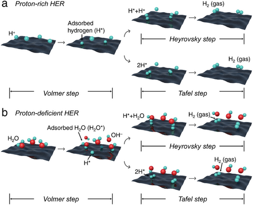
Obviously, achieving high HER performance under proton-deficient conditions depends not only on optimizing the hydrogen bond strength but also on accelerating the rate of water dissociation. Therefore, it is crucial to focus on the strategic design of electrocatalysts specifically tailored to enhance water adsorption and dissociation while ensuring efficient hydrogen ad/desorption capabilities.
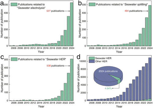
In the context of HER from water electrolysis, optimal electrocatalytic conditions typically require fresh water. However, freshwater constitutes a mere 2.5% of Earth's total water resources, with nearly two-thirds of this valuable freshwater trapped in glaciers or otherwise inaccessible through conventional means.[15] Given this scarcity, the growing hydrogen economy, particularly the production of green H2, which depends heavily on substantial volumes of water, is poised to place significant demand on freshwater resources. Conversely, Earth's vast seawater reserves, combined with abundant offshore wind and solar energy, present a promising solution for seawater-based HER.[16] Coastal regions around the globe are well-positioned to harness renewable electricity and seawater for green H2 production. Notably, coastal arid zones with plentiful photovoltaic resources, such as the Middle East, South Africa, the west coast of the Americas, and Australia, along with areas endowed with substantial wind energy like the north coast of Europe, the south coast of Alaska, the tip of South America, Greenland, and several coastal zones in Australia and Asia, are particularly suited for hydrogen production from seawater. As illustrated in Figure 2a–c, research on seawater electrolysis, seawater splitting, and seawater HER has steadily increased over the past two decades, demonstrating its growing significance for the future. However, despite this progress, studies specifically focusing on seawater HER still represent a small fraction of overall HER research. As of 2024, seawater HER studies account for only 4.64% of total HER publications (Figure 2d). This highlights the urgent need for further development in this area. Utilizing seawater as a resource for H2 production is a crucial step toward realizing a sustainable and clean energy future.
Despite the many challenges faced in the early stages of developing H2 production, storage, and transport systems, significant technological and material breakthroughs are steadily advancing the industrialization of hydrogen energy. In the area of electrocatalyst design for water and seawater electrolysis, existing reviews have typically categorized their discussion based on electrocatalytic materials such as Pt-, Ru-, and Mo-based electrocatalysts, or transition metal oxides, nitrides, chalcogenides, and phosphides. Additionally, other classifications have been made based on modification techniques like doping, alloying, defect inclusion, and interface engineering. However, most of these discussions have focused solely on catalytic activity or performance at low current densities, frequently overlooking the cost-effectiveness and practicality required for scaling H2 production to industrial levels.
Hence, as shown in Figure 3, this review brings together the most recent and progressive studies on green H2 production, with a particular emphasis on HER and seawater HER electrocatalysis. It highlights the critical need for developing cost-effective, self-supported, hydrophilic, mechanically robust, and electrochemically stable electrocatalysts to facilitate both water and seawater electrolysis at an industrial scale. Emphasis is placed on integrating high catalytic activity with physical and electrochemical stability while ensuring the scalability of fabrication processes to meet the demands of industrial-scale H2 production. The review also emphasizes the advancements in HER coupled with organic oxidation reactions, which replace traditional anodic oxygen evolution reaction (OER) electrocatalysis with organic oxidation processes to improve overall efficiency. Additionally, it addresses specific strategies to enhance HER and OER activity and stability in actual seawater conditions, such as designing internal channels, surface ion-sieving layers, and Lewis acid layers on electrocatalysts. Furthermore, the review explores the design of electrolyzers, particularly their internal membranes, with a focus on meeting the increased demands of H2 production at scale. For the first time, it advances the discussion of electrocatalysts and electrolyzers, particularly for seawater applications, from the perspective of industrial-scale H2 production. By prioritizing realistic utility and scalability, this review provides a new perspective aimed at bridging the gap between laboratory research and industrial implementation.
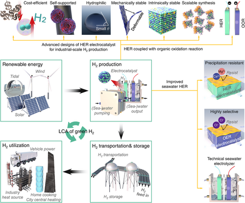
In addition to green H2 production, this review highlights recent advancements in H2 storage and transportation, demonstrating novel material developments and innovative methods employed across various countries. Moreover, it presents comparative analyses and discussions on the H2 industrial chain and market potential, based on current enterprises and projects. The aim is to provide readers with diverse perspectives and insights on H2 industrialization, promoting further development in this field. Finally, the LCA studies are coordinated to validate the environmental benefits of using renewable energies to produce green H2, promoting further development in the field of H2 industrialization (Figure 3). Through this comprehensive review, we anticipate the establishment of a foundational link in the understanding among laboratories, industry, and the broader community toward advancing future green H2 technologies.
2 Challenges and Progresses of H2 Production
2.1 Challenges of HER Electrocatalysts
2.1.1 Cost-Efficiency of HER Electrocatalysts
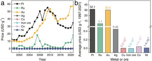
To date, the efficient catalysis of the HER typically relies on platinum-group metals, such as Pt and Ru, due to their ideal metal–H bond strengths of ≈62 and 65 kcal mol−1 for Pt–H and Ru–H, respectively. These strengths facilitate a balance between hydrogen adsorption and desorption, enabling a kinetically rapid HER.[17, 18] However, as indicated in Figure 4a,b and reported by the National Minerals Information Center, the average price of Pt over the last 20 years has exceeded that of Au and is 71.3 times higher than that of Ag. Compared to more common metals like Cu, Fe, Co, and Ni, elements of Pt and Ru entail significantly higher costs, which poses a strong financial burden on the development of HER electrocatalysis.[19-25] Therefore, in the mass production and development of industrial-scale electrocatalysts, strategies to reduce or replace platinum-group metals are crucial to lower the costs associated with H2 production.
2.1.2 Scalable and Stable H2 Production
Undoubtedly, in addition to HER activity, the durability of an electrocatalyst that can operate under industrial-scale current densities (higher than 500 mA cm−2) is essential for the industrialization of HER. While the performance of HER electrocatalysts can initially be evaluated by the strength of the metal–H bond at low current densities, at higher currents, factors such as interfacial charge transfer resistance, coverage rate of intermediates, electrocatalytic durability, and H2 bubble release kinetics must also be considered.[26-29] For example, sluggish electron transfer often occurs on layered transition metal dichalcogenides (TMDs) due to large interlayer potential barriers,[30] or increased electrocatalytic impedance can arise in assembled electrocatalysts that require post-coating with binders and conductive agents.[31] Typically, advanced electrocatalysts exhibit Tafel slopes of ≈30 mV dec−1 at low current densities; however, these slopes often rise above 120 mV dec−1 at higher densities, limited by real-world proton diffusion and adsorption characteristics.[14, 32] Additionally, subsequent inefficient H2 desorption at these higher current densities can block electrocatalytic active sites, impeding electron and mass transfer during HER.[33, 34] Furthermore, under high HER current densities, the elevated reaction potentials and rapid H2 bubble formation can cause the electrocatalyst layers to detach from their substrates due to weak adhesion, a common issue in conventionally assembled electrocatalysts.[35, 36] Overall, developing an electrocatalyst capable of withstanding the demanding conditions of industrial-scale H2 production remains a significant challenge.
2.2 Advanced Designs of HER Electrocatalysts
2.2.1 Cost-Efficient Electrocatalysts
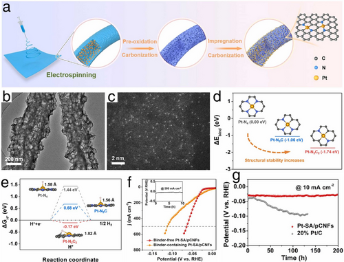
Considering the superior activity of Pt-based electrocatalysts, efforts to reduce the cost of HER have initially focused on the development of Pt nanocluster or single-atom electrocatalysts. These strategies aim to achieve high HER performance by maximizing active surface areas while minimizing the quantity of Pt used. For instance, Han et al. developed a novel Pt single atom electrocatalyst supported on N-doped porous carbon nanofibers (Pt-SA/pCNFs), employing electrospinning followed by carbonization to form the nanofibers, and impregnation followed by pyrolysis to synthesize Pt-SA/pCNFs, as depicted in Figure 5a.[37] In the Pt-SA/pCNFs, the porous structure of the N-doped carbon nanofibers, shown in the transmission electron microscope (TEM) image in Figure 5b, imparted significant hydrophilicity, enhancing the HER electrocatalysis. As presented in Figure 5c, the high-angle annual dark-field scanning transmission electron microscopy (HAADF-STEM) image illustrated that the Pt single atoms were anchored through strong interactions from tailored N and C, forming a stable Pt─N2C2 configuration, which led to exceptional Pt atomic utilization and electrocatalytic activity. Additionally, the density functional theory (DFT) results depicted in Figure 5d,e highlight a small negative binding energy at the Pt─N2C2 site and near-zero Gibbs free energy of hydrogen intermediate (ΔGH ⃰) for the Pt-SA/pCNFs, indicating robust structural stability and HER activity. Remarkably, in a 0.5 m H2SO4 electrolyte, the Pt-SA/pCNFs electrocatalyst achieved an exceptionally low overpotential of 64 mV at a high current density of 500 mA cm−2, maintaining stability with minimal decay over 200-h at 10 mA cm−2 and 10-h at 500 mA cm−2 (Figure 5f,g). These results suggested a promising potential for large-scale H2 production using the Pt-SA/pCNFs electrocatalyst.
According to the statistical analysis previously presented in Figure 4, the cost of Pt significantly exceeds that of other metals such as Ru, Cu, Fe, Co, and Ni. Consequently, the long-term development of HER technologies based on Pt is not sustainable. In response, researchers have explored numerous transition metal-based HER electrocatalysts as alternatives to Pt, benefiting from their lower cost and adjustable HER activity through doping or alloying processes.
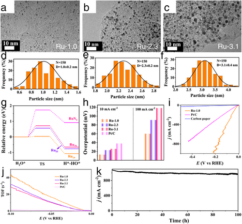
In terms of single transition metal-based HER electrocatalysts, as presented in Figure 6a–f, Hu et al. designed the Ru nanocrystals ranging from nanoparticles to sub-nanoclusters and single atoms through a calcination process in H2/Ar flow.[38] In this work, the diameter of Ru directly influenced the d-band center of fabricated Ru nanocrystals, with the smallest Ru clusters exhibiting an upshifted d-band center that provided enhanced water dissociation capability compared to Ru nanoparticles and single atoms, thereby improving HER activity, especially under proton-deficient conditions (Figure 6g). Additionally, the cluster morphology of Ru increased the specific surface area and significantly boosted the number of active HER sites. Consequently, Ru clusters demonstrated superior alkaline HER activity, achieving a very low overpotential of 13 mV at a current density of 10 mA cm−2 and a high turnover frequency (TOF) of 43.3 s−1 at a potential of 100 mV (Figure 6h,j). Remarkably, as shown in Figure 6i,k, Ru clusters could achieve a large current density of 1000 mA cm−2 at just overpotential of 196 mV when a mass of Ru loading on electrode reached to 1 mg cm−2, along with maintaining stability over 100-h at this high current density without significant degradation. These exceptional HER performances demonstrated the potential for industrial-scale H2 production using cost-effective Ru-based electrocatalysts.
To further enhance the cost-efficiency of HER using transition metals, TMDs and transition metal phosphides (TMPs) have gained tremendous attention recently. The layered structure of TMDs, with abundant exposed edge sites, is typically considered rich in active sites for HER electrocatalysis.[39] Concurrently, the more electrically conductive TMPs feature numerous triangular prism structures that can expose additional crystal planes and potential HER active sites.[40] Based on this understanding, through a colloidal reaction, Kwak et al. synthesized the Nb1–xVxSe2 nanosheets across the full compositional range of x.[41] At x = 0.3, the Nb1–xVxSe2 nanosheets exhibited the lowest overpotentials of 236 and 298 mV at current densities of 10 and 100 mA cm−2 respectively, with a Tafel slope of 72 mV dec−1. The chronoamperometry stability test at current densities of 10 and 20 mA cm−2 showed no noticeable current reduction after the long-term stability test, and even after 5000 linear sweep voltammetry (LSV) cycles, the overpotentials of Nb1 − xVxSe2 nanosheets remained at 238 and 302 mV at current densities of 10 and 100 mA cm−2 respectively, with only negligible decay.
2.2.2 Self-Supported Electrocatalysts
To facilitate industrial-scale H2 production with robust durability, managing disruptions from rapid H2 bubble evolution is crucially dependent on the adhesive strength of electrocatalysts applied to electrodes. However, in cases involving large current densities and extensive H2 bubble formation, the electrocatalyst layer, often combined with a binder and conducting agent, can easily detach due to insufficient adhesion. This detachment not only buries active sites but also leads to increased impedance in HER.[31] To address this challenge, researchers have developed various self-supported electrocatalysts, designed to prevent peeling and secondary aggregation through the in situ growth of electrocatalysts on substrates. These substrates, equipped with active electrocatalysts, can then be directly utilized as working electrodes in HER electrocatalysis.
As demonstrated in Figure 7a, Ni et al. successfully in situ constructed a hierarchically self-supported HER electrode, through the integration of Cu nanowires, NiFe nanosheets, and Pt3Ir alloy nanoparticles (Cu NWs@NiFe-Pt3Ir).[42] DFT calculations confirmed that the coupling between NiFe and Pt3Ir significantly enhanced the HER kinetics by facilitating electron consumption at the electrode–electrolyte interface (Figure 7b–d). Additionally, as shown in Figure 7e,f, incorporating Ir atoms into the Pt3Ir structure lowered the d-band center energy level of the Pt 5d orbital, optimizing H* adsorption and desorption during HER electrocatalysis. Leveraging its hierarchical structure with numerous active sites and the in situ contact structure, the Cu NWs@NiFe-Pt3Ir electrode achieved exceptionally low HER overpotentials of only 210 and 239 mV to reach industrial-scale current densities of 500 and 1000 mA cm−2 in 1 m KOH, as evidenced by the corresponding TEM images and HER activities displayed in Figure 7g,h. In terms of electrochemical stability, as shown in Figure 7i, the Cu NWs@NiFe-Pt3Ir self-supported electrocatalyst consistently produced H2 for 7 days, even under a substantial current density of 500 mA cm−2, with an inappreciable potential increase of only 8 mV. This expertly designed self-supported electrode demonstrated outstanding HER activity and durability at an industrial scale.

Furthermore, through a straightforward electrospinning strategy optimized with pyrolysis temperature and precursor mass ratios, Ouyang et al. effectively developed in situ grown and self-supported Mo2C@carbon nanofibers (Mo2C@C NF) film demonstrating exceptional HER electrocatalytic performance.[43] This self-supported electrocatalyst avoided the occlusion of active sites and enhanced the diffusion of electrons and reaction intermediates during HER electrocatalysis. Consequently, the Mo2C@C NF achieved a low overpotential of 86 mV at a current density of 10 mA cm−2 and a minimal Tafel slope of 43 mV dec−1 in 1 m KOH. Thanks to its robust construction from in situ growth, the Mo2C@C NF displayed outstanding electrocatalytic stability in alkaline HER, maintaining stability for 340-h and 100-h at current densities of 20 and 50 mA cm−2, respectively. Similarly, Liu et al. developed a mechanically stable, all-metal, and highly efficient CuMo6S8/Cu electrode through an in situ reaction between MoS2 and Cu.[44] The resulting electrocatalyst demonstrated robust interfacial binding between the active CuMo6S8 and support Cu while exhibiting weak adhesion between the CuMo6S8/Cu interface and H2 bubbles. This unique combination effectively prevented electrocatalyst detachment and enhanced reaction kinetics at industrial-scale current densities. As a result, in a 1 m KOH electrolyte, the self-supported CuMo6S8/Cu electrocatalyst achieved a remarkably low overpotential of 334 mV and demonstrated stable operation for over 100 h at a high current density of 2500 mA cm−2.
2.2.3 Hydrophilic Electrocatalysts
Obviously, a well-designed self-supported electrocatalyst with robust durability can effectively resist the bubble disturbance to maintain steady H2 generation. However, during industrial-scale HER with rapid H2 bubble generation, the diffusion and adsorption of intermediates (e.g., protons, H*, and H2O*) are also significantly impacted by the kinetics of H2 bubble release during the HER processes. In practice, when H2 bubbles extensively cover the surface of the electrocatalyst, the occupied air zones seriously obstruct the diffusion of water molecules and protons to the electrocatalytic active sites at the interface between the electrocatalyst surface and the electrolyte.[45] Additionally, these occupied air zones can cause an inhomogeneous current distribution on the electrocatalyst surface, increase the HER overpotentials in areas not covered by H2 bubbles, and ultimately lead to premature degradation of the electrocatalyst durability.[46] Therefore, to facilitate the rapid release of H2 bubbles, designing HER electrocatalysts with more hydrophilic (i.e., aerophobic) surfaces is advantageous. This design ensures that the electrolyte, rather than the H2 bubbles, preferentially contacts the electrocatalyst surface, thereby enhancing the exchange efficiency of intermediates during HER electrocatalysis.
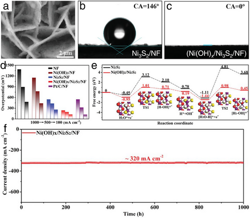
The highlighted work from He et al. introduced a free-standing heterostructure electrocatalyst,[47] consisting of microporous Ni(OH)x/Ni3S2 on Ni foam (Ni(OH)x/Ni3S2/NF presented in the scanning electron microscopy (SEM) image in Figure 8a. As demonstrated in Figure 8b,c, compared to the pristine Ni3S2/NF (water contact angle of 146°), this well-designed heterostructure electrocatalyst exhibited a water contact angle of 0°, indicating an absolute hydrophilic property. This exceptional wettability ensured a high utilization rate of active sites on the Ni(OH)x/Ni3S2/NF electrode and supported continuous H2 production even under long-term, high-current-density HER electrocatalysis. Leveraging its microporous and self-supported structures, the Ni(OH)x/Ni3S2/NF exhibited remarkable HER activity and stability in 1 m KOH electrolyte, achieving overpotentials of just 126, 193, and 238 mV to reach substantial current densities of 100, 500, and 1000 mA cm−2, respectively (Figure 8d). These impressive HER activities were further corroborated by DFT calculations (Figure 8e), which indicated that easy H2O dissociation and reduced H* adsorption significantly enhance HER kinetics. Additionally, a 1000-h long-term durability test conducted under a high current density of ≈320 mA cm−2 showed no significant decay (Figure 8f). These results surpassed those of commercial Pt/C electrocatalysts, positioning this as a leading HER performer among recently reported state-of-the-art non-noble metal electrocatalysts.
Further study focusing on the hydrophilic modification of HER electrodes is highlighted in Sun's study.[48] Through a combination of hydrothermal and chemical etching processes, crystalline nickel tellurium nanorods enclosed by amorphous rhodium hydroxide (a-Rh(OH)3/NiTe) were produced. Notably, the resulting a-Rh(OH)3/NiTe demonstrated a significantly enhanced hydrophilic property, exhibiting a water contact angle of ≈0°. This superhydrophilic surface of a-Rh(OH)3/NiTe ensured close contact between the electrocatalyst and the electrolyte during HER processes, facilitating accelerated electrocatalytic kinetics through rapid electron and mass exchange. Attributed to these superiorities, the a-Rh(OH)3/NiTe achieved exceptionally low HER overpotentials of only 51, 109, and 64 mV in 1 m KOH, 1 m PBS, and 0.5 m H2SO4 to reach a current density of 100 mA cm−2, alongside robust electrochemical stability. Moreover, Luo et al. synthesized molybdenum disulfide microspheres modified with molybdenum carbide nanoparticles (MoS2/Mo2C) through a combination of hydrothermal and chemical vapor deposition processes.[49] The unique structure of the microspheres, composed of numerous aligned MoS2 nanosheets, generates a strong capillary force that efficiently pumps the electrolyte onto the MoS2/Mo2C surface. This significantly reduces gas–solid adhesion and facilitates the rapid detachment of H2 bubbles, as evidenced by the nearly zero contact angle when using a 1 m KOH droplet. Furthermore, the presence of a large number of exposed active Mo2C nanoparticles at the edges of the MoS2 nanosheets enhances catalytic performance. The resulting MoS2/Mo2C electrocatalyst demonstrates remarkably low overpotentials of 227 and 220 mV at a high current density of 1000 mA cm−2 in acidic and alkaline conditions, respectively. Additionally, it exhibits excellent electrochemical stability in both catalytic media.
2.2.4 Mechanically Stable Electrocatalysts
During industrial-scale HER, the rapid formation and detachment of large volumes of H2 bubbles typically exert significant force on the electrocatalysts, often leading to the deformation of electrocatalysts and degradation of HER performance. In such cases, the flexibility and adaptability of the electrocatalysts become crucial in alleviating the tension and vibration generated by the release of H2 bubbles.[50]
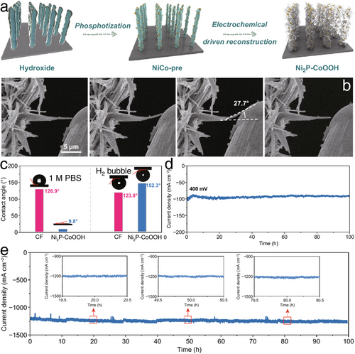
Zhang et al. designed a 2D CoOOH sheet-encapsulated Ni2P (Ni2P–CoOOH) tubular array electrocatalytic system,[51] where the 2D stacked structure acted as an adaptive material to buffer the impact of H2 bubble rupture and evolution by releasing stress (Figure 9a). As shown in Figure 9b, during the bending deformation and restoration processes, the single nanotube of Ni2P–CoOOH demonstrated remarkable flexibility, withstanding a maximum bending angle of up to 27.7° and fully recovering once the external force was removed. Moreover, the porous structure of Ni2P–CoOOH, as evidenced by the contact angle results in Figure 9c, enhanced electrolyte contact with the electrode surface and facilitated H2 bubble detachment. As a result, the well-engineered Ni2P–CoOOH system demonstrated outstanding long-term HER stability, operating for over 100 h at current densities of 2000, 1200, and 100 mA cm⁻2 in alkaline, neutral water, and seawater, respectively (Figure 9d,e). These results signify a promising transition from laboratory-scale to industrial-scale water electrolysis. Similarly, Wang et al. employed dealloying and potentiostatic polarization techniques to develop a flexible, nanostructured Zr-based amorphous HER electrocatalyst.[52] During the dealloying process, sharp cracks were mitigated through potentiostatic polarization, resulting in low-stress concentration and high flexibility. The porous structure of the synthesized electrocatalyst delivered a low HER overpotential of 53 mV at a current density of 10 mA cm−2 in 1 m KOH, along with long-term stability under an industrial-scale current density of 300 mA cm−2 for 100 h.
2.2.5 Intrinsically Electrochemically Stable Electrocatalysts
By implementing in situ growth and optimizing surface morphology to facilitate rapid H2 bubble detachment, improved HER activity and stability have been achieved through stable electrocatalyst structures. These advancements can be extended to a wide range of electrocatalytic materials. Besides, a certain group of electrocatalysts possess inherent properties that withstand against electrochemical decay, such as electrocatalytically active materials protected by another fence layer, in situ self-reconstruction at the electrocatalyst surface, and dealloying processes during HER electrocatalysis.
Utilizing this concept of protective fence engineering for efficient and steady alkaline HER, Huang et al. successfully shielded highly active cobalt-doped MoS2 with a molecule-selective CoS2 barrier fence (Co─MoS2@CoS2).[53] DFT studies showed that the CoS2 barrier prevented the penetration of O2 and OH− ions species while allowing reactant H2O to pass through, thereby preventing surface poisoning of the Co─MoS2 catalyst during alkaline HER electrocatalysis. Simultaneously, the CoS2 barrier also helped to prevent the oxidation or dissolution of active Co─MoS2 into the electrolyte in the form of MoO42− and SO32−. These engineered modifications to Co─MoS2@CoS2 enhanced both HER activity and stability without compromise. In terms of electrochemical stability, Co─MoS2@CoS2 maintained a long-term 120-h test with negligible activity decay at a constant potential of 100 mV. These enhanced HER performances after the protective fence engineering undoubtedly provided a viable blueprint for developing highly active and long-term stable HER electrocatalysts.
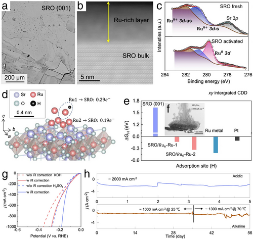
Similarly, in terms of the electrochemical stability enhancements, Zhang's work demonstrated a notable enhancement in electrochemical stability through an in situ self-reconstruction phenomenon on the surface of the designed electrocatalyst.[29] Investigating Sr2RuO4 bulk single crystals during a high current density HER test revealed the in situ formation of ferromagnetic Ru clusters on the surface of Sr2RuO4, evidenced by numerous micro-scale Ru islands as shown in Figure 10a,b, with the formation of Ru clusters confirmed by using X-ray photoelectron spectroscopy (XPS) test (Figure 10c). This in situ exsolution of Ru from Sr2RuO4, subsequently re-incorporated into the Sr2RuO4 bulk crystal, not only improved the cohesion between the Ru clusters and the Sr2RuO4 substrate but also ensured overall electrocatalyst stability and uniform distribution of Ru clusters, which is advantageous for HER activity due to accelerated kinetics in the electron mobility. The corresponding electron redistribution and improved electrocatalytic activity were validated via DFT calculations, as depicted in Figure 10d. Here, the Ru atoms at the top of the Ru6 clusters are identified as HER active sites, exhibiting a ΔGH ⃰ value comparable to that of a Pt catalyst (Figure 10e), and significantly lower than that of the original Sr2RuO4. Remarkably, the in situ self-reconstructed Ru clusters on Sr2RuO4 also formed highly porous and hierarchical structures that facilitated the growth and detachment of H2 bubbles (Figure 10f), simultaneously enhancing mass transfer efficiency and the mechanical stability of the electrocatalyst, particularly at industrial-scale current densities. Ultimately, as demonstrated in Figure 10g,h, the reconstructed Ru6/Sr2RuO4 achieved ultra-low overpotentials of 182 and 278 mV to reach exceptionally high current densities of 1000 mA cm−2 in 0.5 m H2SO4 and 1 m KOH, respectively. Coupled with robust electrochemical stability, continuous testing over 56 days at initial temperatures of 25 °C followed by 70 °C, at a high current density of 1000 mA cm−2, demonstrated the impressive HER performance of this well-reconstructed Ru6/Sr2RuO4 electrocatalyst. These remarkable results confirmed the viability of using this advanced electrocatalyst for industrial-scale H2 production through HER electrocatalysis.
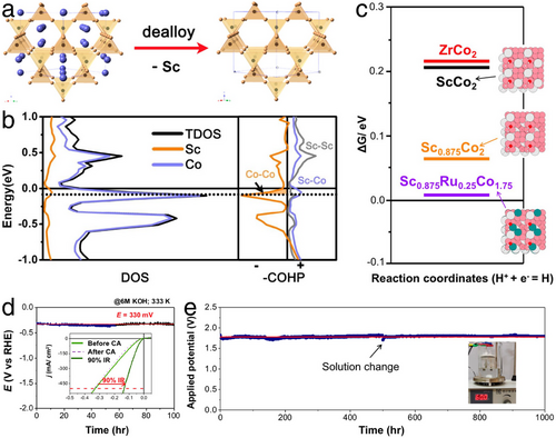
Furthermore, leveraging the dealloying processes as illustrated in Figure 11a, Ji et al. developed optimal HER electrocatalysts using ScRu0.25Co1.75, characterized by zeolite-like metal frameworks.[54] Initially, the minor presence of Ru in ScRu0.25Co1.75 did not alter the dealloying behavior, which involved stripping Sc metal from the center of tunnel structures, thereby forming voids or vacancies in the ScRu0.25Co1.75 structure and significantly increasing the electrocatalytically active surface areas. Further, as shown in Figure 11b, the total density of state (TDOS) indicated a slight downward shift in Fermi level (EFermi) for Sc0.875Co2 (partially Sc stripped) compared to pristine ScCo2. Yet, combined with the crystal orbital Hamilton population (COHP) results presented in Figure 11b, this downshift led to a depopulation of the antibonding states of the Co─Co bond, thereby strengthening the Co–Co connection in Sc0.875Co2. These structural changes, brought about by dealloying engineering, significantly enhanced the electrocatalytic stability of ScRu0.25Co1.75. Additionally, the depopulation of the antibonding states of the Co─Co bond improved the Co─H bond in Sc0.875Co2, potentially increasing H* adsorption following Sc stripping to enhance HER electrocatalysis (Figure 11c). As a result, under industrial HER conditions in 6 m KOH at 60 °C, ScRu0.25Co1.75 achieved an overpotential of only 132 mV to reach a high current density of 500 mA cm−2 (Figure 11d) and demonstrated 1000-h long-term stable H2 production (Figure 11e). These enhanced properties of ScRu0.25Co1.75, derived from the dealloying processes during HER electrocatalysis, demonstrated its potential for industrial-scale H2 production.
2.2.6 Large-Scale Synthesis of Electrocatalysts
For industrial-scale H2 production, an ideal HER electrocatalyst should be easily manufactured in large quantities, avoiding complex or low-yield initial laboratory synthesis methods such as high-temperature annealing in various atmospheres.[55] In recent years, large-scale synthesis of diverse electrocatalysts in ambient conditions has remained popular, utilizing representative methods such as room-temperature immersion synthesis, centrifugal spinning fabrication, and ball-milling manufacturing.
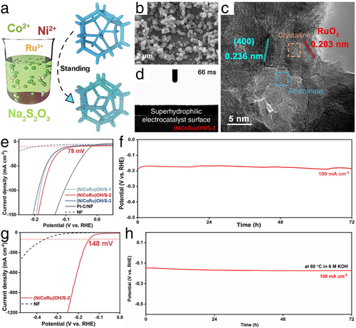
The classic room temperature immersion synthesis by Yang et al. developed a well-designed NiCoRu hydroxide/sulfide heterostructure on Ni foam (i.e., (NiCoRu)OH/S).[56] As illustrated in Figure 12a, the (NiCoRu)OH/S electrocatalyst can be readily produced through industrial-scalable room temperature soaking for in situ growth on Ni foam. According to the characterized results shown in Figure 12b, after four days of room temperature immersion, abundant (NiCoRu)OH/S nanoparticles were distributed on the Ni foam substrate, significantly increasing the specific surface areas and enhancing electron and mass transfer during HER electrocatalysis to accelerate the final HER kinetics. Additionally, the coexistence of crystalline and amorphous planes in (NiCoRu)OH/S exposed numerous active sites (Figure 12c), further facilitating electron transfer. Coupled with the confirmed superhydrophilic properties shown in Figure 12d and intrinsic HER activity from the multiple chemical states of the trimetallic compound, the (NiCoRu)OH/S-2 sample treated with optimal immersion time demonstrated remarkable HER activity with a low overpotential of 78 mV at a current density of 10 mA cm−2 and maintained 72-h robust electrochemical durability tested at a constant current density of 100 mA cm−2 in 1 m KOH (Figure 12e,f). Even under industrial operation conditions in 6 m KOH at 60 °C, (NiCoRu)OH/S-2 required overpotentials of only 148 and 250 mV to reach high current densities of 100 and 1200 mA cm−2, respectively, maintaining 72-h robust durability at a constant current density of 100 mA cm−2 (Figure 12g,h). Beyond excellent HER performance, (NiCoRu)OH/S-2 also served as an effective OER electrocatalyst, showing outstanding OER activity and stability even under industrial conditions. This sophisticated heterostructure electrocatalyst, (NiCoRu)OH/S, holds promise as a ready-to-use bifunctional electrode, poised to advance the industrialization of HER technologies.
Compared to electrospinning, which has low throughputs and requires high voltage, centrifugal spinning technology generally achieves higher throughputs. Typical centrifugal spinning equipment with two nozzles can produce ≈50 g h−1, a rate nearly two orders of magnitude higher than that of laboratory-scale electrospinning. Utilizing an in-house developed centrifugal spinning setup, Mukkavilli et al. produced TaOxN1 − x fibers through ammonolysis of as-spun ([Ta(OEt)5]2)/polyvinylpyrrolidone (PVP) fiber mats.[57] Consequently, the TaOxN1 − x fibers demonstrated superior HER activity compared to Ta2O5. This centrifugal spinning method undoubtedly provides a universal scalable approach for producing other up-scaled electrocatalysts in the future. Moreover, as a prominent solvent-free mechanochemical technique, the high-energy ball milling approach is straightforward and highly scalable, suitable for producing large quantities of electrocatalysts. In this context, Hu et al. utilized graphene quantum dots (GQDs) as exfoliation agents to synthesize and functionalize nearly atom-layered MoS2 nanosheets (ALMS).[58] Impressively, the produced ALMS measured ≈4 nm and could be uniformly dispersed in isopropanol, forming a stable colloidal solution due to the sulfonation process facilitated by GQDs, demonstrating that the scaled-up-fabricated ALMS can be reliably stored. Without requiring organic solvents, catalysts, substrates, or the harsh conditions of vacuum systems, the synthesis yield of ALMS reached 63% with efficient recovery and recycling of GQDs as an exfoliation agent, ensuring a reliable and scalable production of electrocatalysts for industrial HER needs. Finally, the produced ALMS exhibited considerable HER activity and outstanding electrochemical durability even after a 200-h long-term stability test in 0.5 m H2SO4 solution. The development of this stable 2D nanomaterial electrocatalyst provides a feasible route for producing electrocatalysts on a large scale, aiming to meet the increasing demands for HER industrialization.
To provide a clear understanding of the current state of green H2 production, we have summarized the advanced designs of HER electrocatalysts in Table 1 with taking into account various key properties of the reviewed electrocatalysts, such as cost-effectiveness, self-supporting structures, hydrophilicity, mechanical stability, intrinsic electrochemical stability, and scalable designs to satisfy the high demands of HER electrocatalyst for enabling industrial-scale H2 production. In addition, we further analyzed hundreds of studies closely related to the topic of high-performance HER in recent three years. Specifically, an industrial-scale current density normally should exceed 500 mA cm−2, also along with a long-term stable utilization. However, as shown in Figure 13a and Table S1 (Supporting Information), although most HER studies have demonstrated progressively lower overpotentials even at a current density of 100 mA cm−2, electrochemical stability remains largely limited to low current densities and short testing durations (Figure 13b). Additionally, the analyzed degradation rate of voltage presented in Figure 13c still falls significantly short of the DOE 2026 target, both in terms of operating current density and the average voltage degradation rate. These results clearly indicate that the development of scalable and stable electrocatalysts is an essential future direction for generating green H2. Furthermore, to achieve scalable and stable H2 production, it is essential to integrate the key qualities discussed in this chapter—such as cost efficiency, self-supporting architecture, hydrophilicity, mechanical robustness, and intrinsic electrochemical stability—into a single, all-in-one electrocatalyst for ensuring efficient and long-term stable water electrolysis. Ultimately, this well-designed electrocatalyst should be a scalable synthesis to meet the large demands of industrial H2 production.
| Electrocatalyst property | Electrocatalyst | Activity | Stability | Electrolyte |
|---|---|---|---|---|
| Cost-efficient | Pt-SA/pCNFs[37] | 64 mV at j of 500 mA cm−2 | 200-h at j of 10 mA cm−2 | 0.5 m H2SO4 |
| 10-h at j of 500 mA cm−2 | ||||
| Ru clusters[38] | 13 mV at j of 10 mA cm−2 | 100-h at j of 1000 mA cm−2 | 1 m KOH | |
| 196 mV at j of 1000 mA cm−2 | ||||
| Self-supported | Cu NWs@NiFe-Pt3Ir[42] | 210 mV at j of 500 mA cm−2 | 168-h at j of 500 mA cm−2 | 1 m KOH |
| 239 mV at j of 1000 mA cm−2 | ||||
| Mo2C@C NF[43] | 86 mV at j of 10 mA cm−2 | 340-h at j of 20 mA cm−2 | 1 m KOH | |
| 100-h at j of 50 mA cm−2 | ||||
| CuMo6S8/Cu[44] | 334 mV at j of 2500 mA cm−2 | 100-h at j of 2500 mA cm−2 | 1 m KOH | |
| Hydrophilic | Ni(OH)x/Ni3S2/NF[47] | 126 mV at j of 100 mA cm−2 | 1000-h at j of 320 mA cm−2 | 1 m KOH |
| 193 mV at j of 500 mA cm−2 | ||||
| 238 mV at j of 1000 mA cm−2 | ||||
| a-Rh(OH)3/NiTe[48] | 51 mV at j of 100 mA cm−2 | 75-h at j of 10 mA cm−2 | 1 m KOH | |
| 109 mV at j of 100 mA cm−2 | / | 1 M PBS | ||
| 64 mV at j of 100 mA cm−2 | 56-h at j of 10 mA cm−2 | 0.5 m H2SO4 | ||
| MoS2/Mo2C[49] | 227 mV at j of 1000 mA cm−2 | 24-h at j of 200 mA cm−2 | 1 m KOH | |
| 220 mV at j of 1000 mA cm−2 | 24-h at j of 200 mA cm−2 | 0.5 m H2SO4 | ||
| Mechanically stable | Ni2P–CoOOH[51] | / | 100-h at j of 2000 mA cm−2 | 1 m KOH |
| 20 mV at j of 10 mA cm−2 | 100-h at j of 1200 mA cm−2 | 1 m PBS | ||
| 194 mV at j of 10 mA cm−2 | 100-h at j of 100 mA cm−2 | Seawater | ||
| Zr-based amorphous alloy ribbons[52] | 53 mV at j of 10 mA cm−2 | 100-h at j of 300 mA cm−2 | 1 m KOH | |
| Electrochemically stable | Co─MoS2@CoS2[53] | 105 mV at j of 10 mA cm−2 | 120-h at j of 100 mA cm−2 | 1 m KOH |
| Ru6/Sr2RuO4[29] | 278 mV at j of 1000 mA cm−2 | 1344-h at j of 1000–1300 mA cm−2 (25 + 70 °C) | 1 m KOH | |
| 182 mV at j of 1000 mA cm−2 | 120-h at j of 2000 mA cm−2 | 0.5 m H2SO4 | ||
| ScRu0.25Co1.75[54] | 132 mV at j of 500 mA cm−2 | 1000-h at j of 500 mA cm−2 (60 °C) | 6 m KOH | |
| Large-scale synthesis | (NiCoRu)OH/S[56] | 78 mV at j of 10 mA cm−2 | 72-h at j of 100 mA cm−2 | 1 m KOH |
| 148 mV at j of 100 mA cm−2 | 72-h at j of 100 mA cm−2 (60 °C) | 6 m KOH | ||
| 250 mV at j of 1200 mA cm−2 | ||||
| ALMS[58] | 270 mV at j of 10 mA cm−2 | 200-h at j of 10 mA cm−2 | 0.5 m H2SO4 |

2.3 HER Coupled with Organic Oxidation Reactions
In the previous chapter, we thoroughly reviewed recent studies on electrocatalyst designs aimed at enhancing HER performance. However, we also recognize that the counterpart anodic OER, involving a sluggish four-electron process, significantly impacts the overall efficiency of water splitting during practical H2 production. In recent years, there has been a growing focus on organic oxidation reactions as alternatives to OER in water splitting, with small organic molecules such as alcohols, aldehydes, or amines being particularly favored. Integrating these organic oxidation reactions with HER electrocatalysis can effectively reduce the overall voltage required for hybrid water splitting due to more favorable thermodynamic and kinetic processes at the anode, thereby indirectly lowering the barriers to H2 production. Additionally, this approach allows for the generation of high-value-added chemicals.[59-61] Consequently, we provide brief reviews of the latest breakthroughs in organic oxidation reaction studies to broaden understanding of HER developments across various related fields.
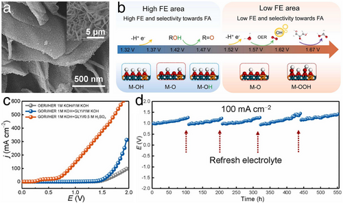
Among these studies, the glycerol oxidation reaction is simpler to be proceeded than traditional water oxidation (i.e., OER). At the anode, not only does the glycerol oxidation reaction reduce the overpotential compared to OER in overall water splitting, but the resulting formic acid (FA) can also be utilized as a high-energy-density fuel for direct formic acid fuel cells. Building on this concept, Song et al. developed an amorphous layered double hydroxide (LDH) enriched with active oxygen sites.[62] As shown in Figure 14a, self-supported amorphous NiFe-LDH (A-NiFe-LDH) nanosheets were developed on Ni foam through an electrochemical amorphization process of crystallized NiFe-LDH. Notably, the hydroxy groups in the host layer of A-NiFe-LDH can be easily deprotonated, particularly at an ultralow voltage, leading to the generation of active oxygens. These active oxygens are beneficial for oxidizing glycerol molecules while suppressing the OER (Figure 14b). This high selectivity toward FA using A-NiFe-LDH can effectively complement cathodic HER electrocatalysis. Consequently, a hybrid electrolyzer comprising an alkaline anode chamber and an acid cathode chamber was designed. This setup achieved low cell voltages of 0.9 and 1.72 V to reach high current densities of 100 and 500 mA cm−2, respectively (Figure 14c). Furthermore, as shown in Figure 14d, this hybrid cell operated for over 500-h with minimal decay at a current density of 100 mA cm−2, upon refreshing the electrolyte at both anode and cathode. Throughout these processes, not only was the typically sluggish OER circumvented by replacing it with the glycerol oxidation reaction, but both desirable H2 and high-value-added FA were also acquired.
Furthermore, Xu et al. have merged methanol oxidation reaction with HER to co-generate value-added formate and H2 using NiIr-based metal–organic framework (MOF) nanosheets in situ arrayed on Ni foam (NiIr-MOF/NF).[63] This bifunctional electrocatalyst served as a self-supported electrode at both anode and cathode, capable of oxidizing methanol while concurrently facilitating H2 production. The electrochemical performance of this hybrid water-splitting system demonstrated that the anodic and cathodic Faradaic efficiencies for formate and H2 were both nearly close to 100% (with no O2 bubble evolution at the anode,). Remarkably, the entire cell operated at a voltage of only 1.39 V to achieve a current density of 10 mA cm−2 in 1 m KOH containing 4 m methanol. Conversely, in a conventional water-splitting setup using pure 1 m KOH, the NiIr-MOF/NF requires a higher cell voltage of 1.56 V to reach the same current density. These results significantly enhanced the energy conversion efficiency in a combined electrocatalysis system of methanol oxidation and HER, producing valuable chemicals and clean hydrogen energy simultaneously.
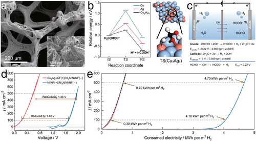
In addition to alcohols, aldehydes have also shown great potential for oxidation processes that can replace traditional water oxidation in OER. Specifically, Li et al. developed a Cu3Ag7 electrocatalyst capable of generating formate and releasing H2 at the anode,[64] utilizing formaldehyde as the organic molecule (i.e. formaldehyde oxidation reaction, Figure 15a). According to DFT analyses depicted in Figure 15b, the intermediate H2C(OH)O* was stabilized on Cu3Ag7 during the hydration of formaldehyde, resulting in a reduced C─H cleavage barrier. When paired with cathodic HER in alkaline conditions (Figure 15c,d), the electrocatalyst achieved remarkably low cell voltages of only 0.22 and 0.60 V for current densities of 100 and 500 mA cm−2, respectively, accompanied by a notable 200% Faradaic efficiency for H2 generation (attributed to both anodic formaldehyde oxidation and cathodic HER). As shown in Figure 15e, the energy consumption for H2 production in this hybrid electrolyzer was significantly lower, only 0.3 and 0.7 kWh m−3 at current densities of 100 and 500 mA cm−2, compared to the energy requirements of conventional water splitting, which are 4.1 and 4.7 kWh m−3, respectively. This demonstrated a substantial reduction in energy demand, emphasizing the efficacy of using aldehyde oxidation reactions as an alternative in electrocatalytic systems.
Similarly, utilizing the successful synthesis of a porous CuAg electrocatalyst through a galvanic replacement method (CuAgglv/Cu), Liu et al. employed biomass-derived furfural as the organic molecule to enhance the anodic reaction in a hybrid water-splitting system combined with cathodic HER, facilitating the production of green H2 at both electrodes.[65] Notably, the oxidation product at the anode, 2-furoic acid, is a crucial raw material for polyethylene furanoate, widely used in the production of edible bottles. This integration of furfural oxidation and HER not only achieved low cell voltages for bipolar H2 production but also generated high-value chemicals from readily available furfural (annually produced at ≈0.43 million tons from inedible lignocellulose). Experimental results demonstrate that increasing the potential from 0.2 to 0.4 V during electrocatalytic oxidative dehydrogenation mitigated the Cannizzaro reaction, thereby inhibiting the formation of furfuryl alcohol. The likely presence of a gem-diol intermediate in both the oxidative dehydrogenation and Cannizzaro reactions of furfural promoted the dissociation of C─H to form 2-furoic acid and H2 on the Cu surface. Utilizing the roughened surface characteristics of CuAgglv/Cu, which enhanced electron and mass transfer, the combined hybrid water-splitting system produced H2 at both anode and cathode with total Faradaic efficiencies of ≈200%, requiring only 0.4 and 0.6 V to reach current densities of 248 and 390 mA cm−2, respectively. This design not only eliminated the potential safety hazards of mixing H2 and O2 as in traditional water-splitting but also ensured pure H2 generation. Moreover, it reduced energy consumption and yielded extra high-value-added chemicals, with an estimated H2 production cost ≈2.51 USD kg−1, making it competitive with the “Green H2” objectives set by the United States Department of Energy (US DOE).[66, 67]
Urea, a well-known amine, can also support water splitting by acting as the fuel for anodic urea oxidation reactions, providing an alternative to the sluggish OER. Employing a sequential hydrothermal-phosphorization-hydrothermal approach, Chen et al. developed a porous Ni foam-supported bimetal phosphide (NiCoPx) nanowire array decorated with ultrathin NiFeCo-MOF nanosheets (NiCoPx@NiFeCo-MOF/NF) for urea-assisted hybrid water splitting.[68] DFT calculations highlighted optimized adsorption energy for COO* of −0.452 eV on the Ni sites within the NiFeCo-MOF, enhancing the generation of intermediates during the urea oxidation reaction. Simultaneously, another part of the NiCoPx exhibited an advantageous ΔGH* value, improving HER efficiency. The well-designed hierarchical structure of NiCoPx@NiFeCo-MOF/NF also enriched the active sites and facilitated electron and mass transfer during the hybrid water-splitting process. As a result, this urea-assisted hybrid water splitting system required a low cell voltage of only 1.54 V to achieve a substantial current density of 100 mA cm−2 in 1 m KOH containing 0.5 m urea solution.
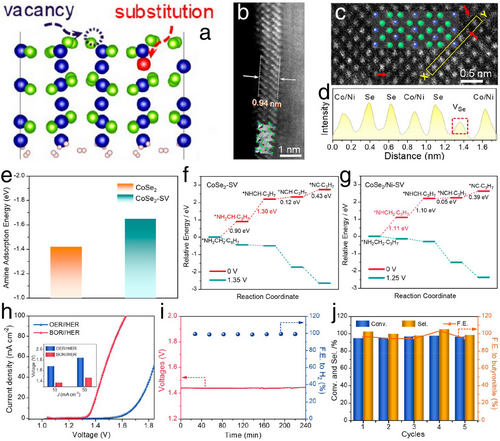
Furthermore, Zeng et al. presented advanced electrocatalysts by developing Se-vacancy and Ni-substitution-employed atomically thin CoSe2 sub-nanometer belts (CoSe2/Ni–SVs SBs) to drive the butylamine oxidation reaction, aiming to replace the conventional anodic OER (Figure 16a–d).[69] Notably, butylamine, a relatively obscure amine species in electrocatalysis, when oxidized, produces butyronitrile, a compound with substantial commercial applications in dye-sensitized solar cells and the chemical and pharmaceutical industries.[70, 71] Additionally, DFT calculations (Figure 16e) revealed that the presence of Se vacancies enhanced the adsorption of N atoms, identifying these sites as strong Lewis acids. Also, Ni substitution in CoSe2/Ni–SVs SBs enhanced the thermodynamics of the dehydrogenation reaction (Figure 16f,g). Consequently, in a hybrid water splitting setup using 1 m KOH and 0.02 m butylamine, CoSe2/Ni–SVs SBs achieved impressively low cell voltages of 1.37 and 1.47 V at current densities of 10 and 50 mA cm−2, respectively, for the anodic oxidation of butylamine and cathodic HER using CoP (Figure 16h). These voltages were 320 and 360 mV lower, respectively than those in conventional water splitting with anodic OER and cathodic HER. Further illustrating the catalytic efficiency, the system demonstrated the absolute selectivity toward butyronitrile with Faradaic efficiencies of 96.7% for butyronitrile and 98.9% for H2 production, maintaining these high rates and efficiencies over five consecutive electrochemical cycles (Figure 16i,j). Thus, utilizing CoSe2/Ni–SVs SBs in hybrid water splitting not only reduced cell voltage but also simultaneously produced H2 and commercially valuable byproducts, presenting a significant improvement over conventional water splitting methods.
In brief, both glycerol and methanol oxidation reactions exhibit significantly lower overpotentials compared to the OER. For instance, glycerol oxidation achieves an overpotential of 0.9 V at a current density of 100 mA cm−2 using A-NiFe-LDH,[62] while methanol oxidation reaches 1.39 V at 10 mA cm−2 using NiIr-MOF/NF.[63] Additionally, the reaction products, such as FA and formate, are high-value-added chemicals. However, glycerol oxidation typically requires a continuous supply of biodiesel by-products, while methanol oxidation depends on the large-scale, renewable production of methanol. Aldehyde oxidation reactions demonstrate ultralow overpotentials and low energy consumption (e.g., 0.22 V at j of 100 mA cm−1 and 0.3 kWh m−3 H2 using Cu3Ag7),[64] but industrial applications are limited due to the toxicity and storage safety concerns of aldehydes like formaldehyde. Meanwhile, urea and amine oxidation reactions exhibit relatively higher overpotentials (e.g., 1.54 V at j of 100 mA cm−1 using NiCoPx@NiFeCo-MOF/NF,[68] and 1.37 V at j of 10 mA cm−2 using CoSe2/Ni–SVs SBs,[69] respectively). However, the resources for these reactions, such as urea-containing wastewater and biomass-derived amines, are readily available, and their products (CO2, N2, and butyronitrile) have extensive industrial applications. Given the ample resource availability and mature technologies (e.g., biodiesel production and wastewater treatment), glycerol and urea oxidation reactions are likely to be rapidly implemented as viable alternatives to OER in water electrolysis. The potential of methanol oxidation reactions is also expected to grow as green methanol production technologies advance. Furthermore, aldehyde and amine oxidation reactions hold considerable potential due to the high-value-added nature of their products. However, achieving this potential will require breakthroughs in ensuring resource safety and improving product separation techniques.
3 Challenges and Progresses of Seawater HER
3.1 Typical Obstacles of Seawater HER
The HER industrialization using seawater presents many benefits. However, seawater HER also faces several challenges due to the complex composition of seawater, including sediment, microplastics, microorganisms, dissolved gases, and complex ion species. Additionally, the physical and chemical properties of seawater can vary significantly based on geographic location and seasonal changes.[72-74] Therefore, a viable approach to seawater HER must address these complexities by ensuring consistent H2 production, high reaction selectivity, and robust corrosion resistance in electrocatalysts.
3.1.1 Precipitations of Seawater HER Electrocatalysts
Admittedly, sediments, microplastics, and microorganisms present in seawater can be readily filtered out prior to seawater HER. However, the removal of many ions (e.g., F−, Cl−, Br−, Na+, Mg2+, K+, Ca2+, Cu2+, Sr2+, Cd2+, HCO3−, CO32− and SO42−, with concentrations detailed in Table 2) poses a challenge, as they cannot be easily eliminated through simple filtration.[75] On one hand, during seawater, HER, the concentration of OH− increases (manifested as a pH increase) alongside H2 evolution at the cathode. This results in the precipitation of Ca(OH)2 and Mg(OH)2, which can cover the electrocatalyst surface, obstructing the active HER sites and ultimately reducing the durability of seawater electrocatalysts. On the other hand, due to the reduction potential at the cathode, ions such as Cu2+ and Cd2+ can undergo reduction to metallic forms under specific potentials instead of contributing to HER. These competitive reactions can similarly block the HER active sites and affect the stability of electrocatalysts during seawater HER.[77, 78] Currently, the addition of buffer electrolytes to stabilize the pH of seawater is a popular method to mitigate these issues.[79] However, this approach also increases costs, hindering the scalability of industrial-scale seawater HER. Consequently, developing seawater electrolyzers that can effectively separate sediments from the cathode surface represents a promising direction. This innovation aims to enable the direct use of seawater for H2 production without additional concerns.
| Dissolved species in seawater | Concentration [ppm] |
|---|---|
| Cl− | 19 500–22 000 |
| Na+ | 10 770–14 039 |
| Mg2+, MgSO4, MgCO3 | 1290–1490 |
| SO42−, NaSO4+ | 905–3200 |
| K+ | 380–469 |
| Ca2+ | 378–421 |
| Br− | 67 |
| HCO3−, CO32− | 28 |
| Cu2+ | 5.3 × 10⁻⁵–2.8 × 10⁻⁴ |
| Cd2+ | 1.8 × 10⁻⁵–9.7 × 10⁻⁵ |
3.1.2 Competitive Anodic Chlorine Evolution
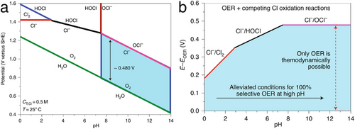
These results indicate that ClER can be circumvented by using a high-performance electrocatalyst that achieves an OER overpotential of less than ≈180 mV in acidic conditions, or less than ≈480 mV in alkaline conditions. Obviously, the latter case is generally more feasible to implement. Nonetheless, achieving industrial-scale current densities at an overpotential under 480 mV presents a significant challenge. Extensive research is needed to enhance activity and simultaneously stabilize the pH to prevent the precipitation of Ca(OH)2 and Mg(OH)2 during the electrocatalytic production of H2 from seawater.
3.1.3 Conventional Electrolyzers for Seawater HER
Given the shift toward using readily available and inexpensive seawater in industrial HER electrocatalysis, conventional water electrolyzers must be adapted to address the specific challenges posed by seawater splitting. Briefly, in this sub-section, we provide an overview of typical traditional electrolyzers, including alkaline water electrolyzers (AWE), proton exchange membrane water electrolyzers (PEMWE), and anion exchange membrane water electrolyzers (AEMWE). The discussion aims to clarify which advantages of these systems should be preserved and which shortcomings or unsuitable aspects need modification for effective seawater electrolysis.
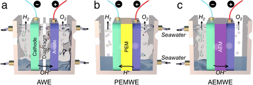
As depicted in Figure 18a, the AWE is a well-established electrolyzer used for water splitting, utilizing a porous diaphragm to separate the cathode and anode. This diaphragm allows the conduction of OH− ions from the cathode to the anode while keeping the produced H2 and O2 gases separate. Notably, when operating an alkaline seawater splitting, non-noble metal-based electrocatalysts can be used, which offer considerable overpotential and stability compared to acidic conditions.[86] As previously mentioned, in OH−-rich environments typical of seawater electrolysis, competitive ClER can be effectively suppressed, enhancing OER performance while maintaining the overpotential below 480 mV. Additionally, the alkaline environment in AWE can precipitate Ca2+ and Mg2+ ions, reducing sediment coverage of Ca(OH)2 and Mg(OH)2 on the cathodic electrode surface, making AWE technology suitable for large-scale seawater electrolysis. However, the porous diaphragm often leads to higher ohmic losses with low working current densities (below 400 mA cm−2) and the inevitable risk of H2 and O2 crossover, which increases the potential for explosions during H2 production.[87, 88] Moreover, the diaphragm can become clogged by ions and impurities in seawater, reducing the efficiency of seawater splitting. Maintaining concentrated alkaline conditions in the AWE system also incurs additional costs for H2 production. The strengths and weaknesses of AWE are detailed and compared with PEMWE and AEMWE in Table 3.
| Electrolyzers | Advantages | Disadvantages |
|---|---|---|
| AWE | Non-noble metal based-electrocatalysts available | Limited electrolysis efficiency |
| OER favorable than ClER | Explosion risks (gas crossover) | |
| Ca2+ and Mg2+ pre-precipitation to avoid the cathodic block | Extra cost on alkaline seawater | |
| PEMWE | No precipitation at the cathode | Competitive ClER than OER |
| High electrolysis efficiency | Stability challenges of PEM and related accessories | |
| Low energy consumption | Competitive Na+ transfer through PEM instead of H+ | |
| Extra-pure H2 generation | High cost on noble metal-based electrocatalysts and other anticorrosive accessories | |
| AEMWE | Non-noble metal based-electrocatalysts available | Limited electrolysis efficiency |
| OER favorable (suppressed ClER) | Stability challenges of AEM | |
| Low cost on AEMWE construction | Serious precipitation at the cathode |
The PEMWE similarly consists of cathode and anode electrocatalysts (predominantly Ir and Pt-based materials) and employs an acidic membrane (i.e., PEM) made from materials like Nafion as a solid electrolyte. This configuration enables the migration of protons from the anode to the cathode, leading to the generation of H2.[89] In PEMWE, seawater is exclusively introduced at the anode, effectively preventing the formation of Ca(OH)2 and Mg(OH)2 precipitates on the cathode surface (Figure 18b). The electrolysis process in PEMWE features faster kinetics compared to AWE due to the high proton conductivity and reduced ohmic loss in the PEM, allowing PEMWE to achieve current densities exceeding 2000 mA cm−2, thus lowering energy consumption for H2 production. Additionally, thanks to minimal H2 and O2 crossover, the purity of the H2 produced (over 99.999%) is significantly higher than that from AWE, also reducing explosion risks during seawater splitting.[90] However, the acidic environment within the PEMWE system makes the ClER more competitive than the OER at the anode. The resultant Cl2 and oxychlorides can severely damage the PEM, electrodes, and bipolar plates in the PEMWE system, degrading overall seawater electrolysis performance and shortening the lifetime of the PEMWE. Furthermore, the high concentration of Na+ in seawater often competes with H+ for passage through the PEM, leading to H+ accumulation at the anode, increasing the Nernst overpotential, and resulting in unstable PEMWE operation. Besides, the use of noble metal-based electrocatalysts and anti-corrosive Ti-based bipolar plates also significantly elevates the fabrication and operational costs of PEMWE (Table 3).[91]
The AEMWE combines elements of both AWE and PEMWE, incorporating cathode and anode electrocatalysts separated by a solid electrolyte of nonporous polymer membrane, known as AEM (Figure 18c). Similar to AWE, AEMWE operates in an alkaline environment, with the AEM facilitating the movement of OH⁻ from the cathode to the anode. Compared to the Nafion-based PEM used in PEMWE, AEM is generally more cost-effective. Introducing seawater exclusively at the cathode reduces the risk of ClER at the anode, which is enriched with OH⁻ rather than Cl⁻. This makes it possible to replace the typically expensive anti-corrosive Ti-based bipolar plates with more affordable stainless steel. Furthermore, the alkaline environment enables the use of non-noble metal-based electrocatalysts, significantly lowering the overall cost of AEMWE.[92] However, despite integrating some advantages of AWE and PEMWE, AEMWE faces challenges. The electrochemical stability of the AEM against Cl− corrosion is suboptimal, and its transport of OH− is slower compared to H+ transport in PEM, resulting in much lower efficiency during seawater electrolysis than PEMWE.[93, 94] Simultaneously, due to the direct supply of seawater to the cathode, the precipitation issue of Ca(OH)2 and Mg(OH)2 during cathodic HER is serious, which covers the cathodic electrode, blocks active sites on the electrocatalyst, and ultimately impedes overall seawater splitting efficiency in AEMWE (Table 3). Meanwhile, in terms of economic competitiveness, the well-established AWE technology is projected to grow at a compound annual growth rate of 6.5% from 2021 to 2028, with the market size expected to reach 180.03 million dollars by 2028 and an H2 production capacity exceeding 3880 Nm3 h−1.[95] However, one of the primary obstacles to further commercialization of AWE remains its high capital expenditure. On the other hand, AEMWE, as an emerging H2 production technology, shows the potential in overcoming the cost-effectiveness limitations of AWE. Although its current H2 production capacity is ≈210 Nm3 h−1, the investment cost remains relatively high at over 2000 USD kW−1, even surpassing that of AWE, which ranges from 500 to 1700 USD kW−1.[96] In brief, the cost-efficiency and investment trends of AEMWE indicate a promising direction for future research and development.
3.2 Improvements of Seawater HER
As highlighted in previous studies, to meet the demands for industrial-scale green H2 production, particularly under conditions of high current densities typically exceeding 500 mA cm−2 and during prolonged HER processes, significant efforts have been directed toward developing cost-efficient and durable HER electrocatalysts capable of large-scale synthesis. These investigations have undoubtedly paved numerous pathways toward developing exceptionally performing HER electrocatalysts, significantly advancing the industrialization of HER. In addition, recent years have seen the emergence of seawater HER as an advanced step in HER industrialization (Figure 2d), aimed at conserving scarce freshwater resources and maximizing the use of abundant seawater and coastal renewable energies, such as offshore wind and solar power. Assuredly, an electrocatalyst designed for freshwater HER typically performs effectively in seawater HER too. Consequently, with the rapid advancements in HER electrocatalyst design, applications for seawater HER have also expanded, leveraging the same HER mechanisms. Despite potential challenges such as precipitations and competitive ClER in seawater HER processes, this review further explores the progress in developing adapted seawater HER electrocatalysts and electrolyzers.
3.2.1 Precipitation Resistant Seawater HER Electrocatalysts
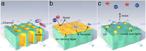
During seawater HER electrocatalysis, the consumption of protons from H2O increases the local concentration of OH− near the cathode, leading to a rise in pH and the formation of precipitates such as Ca(OH)2 and Mg(OH)2 on the active surface of the electrocatalyst. To address this issue, designs for cathodic seawater HER electrocatalysts should focus on self-cleaning of sediments, blocking Ca2+/Mg2+ ions, or maintaining local seawater pH. Based on this understanding, as schematically illustrated in Figure 19a, researchers are developing electrocatalysts with porous or channel-incorporated structures to minimize the retention of precipitates on the surface, allowing precipitates to be carried away with the electrolyte flow. Additionally, Figure 19b shows an HER electrocatalyst coated with an ion-sieving layer that blocks Ca2+ and Mg2+ ions from seawater while permitting the penetration of H2O and OH−, thereby facilitating the seawater HER process. This approach fundamentally reduces the impact of sedimentary corrosion through physical resistance. Moreover, as depicted in Figure 19c, the application of a Lewis acid layer on the electrocatalyst surface is becoming popular. This layer captures the produced OH− from water dissociation, preventing its diffusion into the bulk seawater and the formation of insoluble precipitates. Although these strategies are theoretically sound, practical applications to fully realize these concepts are still in developmental stages.
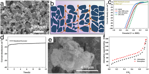
Drawing inspiration from the natural channel structure in plants, Li et al. developed a Mo2C composite electrocatalyst in situ grown on corn straw biochar using a cold isostatic pressure method (Mo2C/B (CIP)), as illustrated in Figure 20a.[97] The schematic in Figure 20b shows that the Mo2C/B (CIP) benefited from an abundance of mesoporous and vertically wide channels, facilitating timely electron exchange and the release of H2 bubbles. Although the formation of precipitates such as Ca(OH)2 and Mg(OH)2 was still inevitable, the natural porous and channel structures in Mo2C/B (CIP) effectively alleviated congestion caused by these precipitates, enabling rapid mass transfer of H2 bubbles and seawater electrolyte through its low-tortuosity channels. As shown in Figure 20c,d, this well-designed seawater HER electrocatalyst demonstrated a notably low overpotential of 251 mV to achieve a current density of 10 mA cm−2 in simulated seawater. Remarkably stable performance was also maintained even after the 12-h seawater HER test, with the specific surface area of Mo2C/B (CIP) maintained at 206.7 m2 g−1, demonstrating its resistance to Ca(OH)2 and Mg(OH)2 precipitations during seawater HER electrocatalysis, as depicted in Figure 20e,f.
In a similar pursuit for sediment resistance during seawater HER, Liu et al. developed a novel Ni foam electrode coated with a Ni(OH)2 nanofiltration membrane (Ni(OH)2–NF), as detailed in Figure 21a.[98] This positively charged Ni(OH)2 membrane with nanometer-scale cracks effectively prevented Ca2+ or Mg2+ from reaching the HER electrocatalyst surface, while permitting the passage of reactants or intermediates such as H2O and OH− during seawater HER processes, as shown in Figure 21b,c. When compared to the bare Ni foam electrode, the Ni(OH)2–NF electrode achieved a dramatic reduction in precipitations by 98.3%, maintaining stable operation for 100-h in a Mg(OH)2-saturated seawater solution, as shown in Figure 21d,e. In the context of a flow-type direct seawater electrolyzer, as depicted in Figure 21f, the system utilizing the Ni(OH)2–Pt–NF electrode (cathodic HER) alongside a Cr2O3–IrRuO2–Ti electrode (anodic OER) exhibited superior resistance to seawater HER precipitations compared to a conventional water splitting system with a Pt–NF cathodic electrode. After a 100-h seawater HER stability test, the sediment accumulation on the Ni(OH)2–Pt–NF electrode was just 0.82 mg cm−2, significantly lower than the 10.06 mg cm−2 on the Pt–NF electrode without the Ni(OH)2 nanofiltration coating, as presented in Figure 21g.

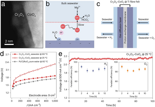
In a notable study aimed at mitigating corrosion from the precipitation of Ca(OH)2 and Mg(OH)2 during seawater HER, Guo et al. implemented a Lewis acid layer on their electrocatalyst design.[99] This novel seawater HER electrocatalyst featured CoOx grown on carbon fibers and encapsulated with a durable Lewis acid layer of Cr2O3, chosen for its electrochemical stability and extremely low pKa value of 2.05, as shown in Figure 22a. This layer effectively captured OH– ions generated during water dissociation in the seawater HER process, thus preventing their diffusion into the seawater and inhibiting the formation of Ca(OH)2 and Mg(OH)2 precipitations on the electrode surface, as illustrated in Figure 22b. Performance results detailed in Figure 22c–e demonstrate that the Cr2O3–CoOx electrocatalyst achieved a low operational cell voltage of only 1.87 V to reach an industrial-scale current density of 1000 mA cm−2 at 60 °C. It also maintained stable performance at a current density of 500 mA cm−2 over 100 h, with high Faradaic efficiencies for H2 (≈93%) and O2 (≈92%) generation in a flow-type seawater electrolyzer using real seawater. This sophisticated design not only effectively supported direct seawater electrolysis but also adapted to industrial-scale current densities and stability requirements.
3.2.2 Highly Selective Anodic Electrocatalysts
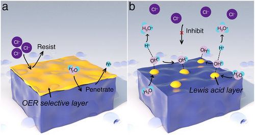
Chloride (Cl−), the predominant anion in seawater (ranging from 19 500 to 22 000 ppm as detailed in Table 2), often undergoes competitive ClER processes at the anode, typically generating corrosive Cl2 gas. While the strategic design of anodic OER electrocatalysts to circumvent ClER indirectly benefits seawater HER activities, minimizing Cl2 damage is crucial for extending the operational life of industrial seawater electrolyzers. As mentioned previously, to achieve industrial-scale current densities in acidic conditions without Cl2 evolution, the applied overpotential must remain below 180 mV, a challenging target seldom met in current research. However, in alkaline conditions, an overpotential up to 480 mV is permissible, which significantly reduces the concern on the competitive ClER. Thus, in view of these obstacles and potential opportunities, and also essential for a comprehensive evaluation of seawater HER progress, recent studies have focused on developing functional seawater OER electrocatalysts, such as those depicted in Figure 23a,b. These include developing an OER-selective layer that blocks Cl− while allowing H2O and H+ to pass through during seawater OER or establishing a localized alkaline environment using a Lewis acid layer on the electrocatalyst surface. This setup creates a stable electrical double layer rich in OH− and H3O+, which effectively prevents localized Cl− migration from the bulk seawater to the electrocatalyst surface, thereby inhibiting competitive ClER at the anodic side of seawater splitting.
In a noteworthy development, Tan et al. engineered an in situ sulfate passivating layer on a Ni foam-supported Ni2Fe-LDH/FeNi2S4 heterostructure (Ni2Fe-LDH/FeNi2S4/NF) during repeated CV scans for OER electrocatalysis.[100] This heterostructure, featuring numerous bimetallic hydroxide/sulfide interfaces, enhanced the adsorption of oxygen intermediates, thereby accelerating OER. Intriguingly, the Cl−-repellent sulfate layer formed in situ on the electrocatalyst surface further extended its application in seawater OER. Following the establishment of this sulfate film, the Ni2Fe-LDH/FeNi2S4/NF demonstrated exceptional performance in alkaline simulated seawater electrolyte, achieving an ultralow OER overpotential of 250 mV at a current density of 100 mA cm−2. The enhanced long-term stability observed post-film formation surpassed the performance of the uncoated Ni2Fe-LDH/FeNi2S4/NF, demonstrating highly increased resistance to Cl− thanks to the post-formed sulfate passivating layer, effectively inhibiting Cl2 evolution in seawater splitting. Similarly, using a two-step approach involving hydrothermal synthesis and electrochemical activation, Kang et al. enhanced the performance of the RuMoNi electrocatalyst for seawater OER.[101] During electrochemical reconstruction, in situ generated MoO42−, formed through the leaching of Mo from the RuMoNi electrocatalyst, effectively repels Cl⁻ from the electrocatalyst surface. This reversible dissolution and precipitation of NiMoO4 results in the formation of a selective MoO42− layer, stabilizing the RuMoNi electrocatalyst for at least 3000 h, even under an industrial-scale current density of 500 mA cm−2, with a minimal voltage degradation rate of 0.64 µV h−1. Remarkably, the system exhibits ≈100% selectivity for alkaline seawater OER. Furthermore, the AEM electrolyzer employing the RuMoNi electrocatalyst achieved seawater electrolysis at a high current density of 1000 mA cm−2 with an applied voltage of just 1.72 V, delivering an energy conversion efficiency of 77.9%. As a result, the calculated cost per gallon of gasoline-equivalent for the produced hydrogen is 0.85 dollars, significantly lower than the DOE 2026 target of 2 dollars. Fan et al. developed the CoFe-Ci@GQD seawater electrolysis electrocatalyst by strategically combining several innovative features.[102] They constructed CoFe-based host layers to enhance OER activity, introduced CO32− into the interlayer to create narrow interlayer spacing and repel Cl⁻ ions, and anchored graphene quantum dots (GQDs) on the catalyst surface to generate Coulomb repulsion, preventing Cl⁻ from accessing surface active sites. Benefiting from these superior characteristics, CoFe-Ci@GQD demonstrated remarkable durability, achieving over 2800 h of alkaline seawater OER operation even at an industrial-scale current density of 1250 mA cm−2. Additionally, the CoFe-Ci@GQD electrocatalyst was integrated as both HER and OER components in a photovoltaic–electrolysis device, achieving a record solar-to-hydrogen efficiency of 18.1% for overall seawater splitting, along with excellent stability for up to 200 h under a high current of 440 mA. These outstanding performances undoubtedly reinforce the potential of green H2 as a sustainable energy solution for the future.
As previously discussed, Guo et al. developed a Cr2O3–CoOx electrocatalyst featuring a Lewis acid layer, which was initially designed to prevent precipitation of Ca(OH)2 and Mg(OH)2 during cathodic HER electrocatalysis.[99] Surprisingly, this same Lewis acid layer proved effective in anodic OER settings, where it helped suppress competitive ClER. As illustrated in Figure 23b and Figure 24a, during seawater OER, H+ ions generated from water dissociation combined with H2O to form H3O+, establishing a stable electrical double layer with excess OH− (partial amount of OH* was consumed for O2 generation), which served as a barrier preventing Cl− from reaching the electrocatalyst surface. As a result, when the Cr2O3–CoOx electrocatalyst was deployed for anodic seawater OER, it demonstrated remarkable Cl− resistance, achieving a 98% suppression rate, as evidenced by the OH− concentration and Cl 2p spectra results shown in Figure 24b,c. By applying an anodic potential of 1.8 V versus RHE, the electrocatalyst maintained over 200-h of long-term stability at large-scale current densities (Figure 24d), confirming its superior Cl− resistance. Consistent with the results presented in Figure 22c–e, in a flow-type seawater electrolyzer using actual seawater, the Cr2O3–CoOx electrocatalyst achieved a low cell voltage of only 1.87 V to support an industrial-scale current density of 1000 mA cm−2 at 60 °C, demonstrating high Faradaic efficiencies for both H2 and O2 production and sustained operational stability.
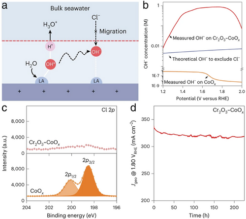
3.2.3 Developments of Seawater Electrolyzers
In the previous section, we comprehensively reviewed the advantages and limitations of traditional AWE, PEMWE, and AEMWE used in seawater electrolysis. Building on this foundation, this section aims to retain the strengths of these conventional electrolyzers while proposing novel ideas and designs to address their existing shortcomings and adaptability issues. These enhancements are intended to improve both the activity and stability of seawater electrolysis. Certainly, the main shortcomings of conventional electrolyzers include issues with membrane conductivity and stability, along with precipitate accumulation on both the membrane and electrodes. These challenges lead to irreversible declines in activity and stability during seawater electrolysis, as noted in previous research.[103] In response, innovations focused on electrolyzer membranes have become a focal area of study. New concepts such as the waterproof breathable membrane combined with self-dampening electrolyte water electrolyzer (WBM-SDEWE), asymmetric water electrolyzer (ASWE), and bipolar membranes water electrolyzer (BPMWE) are emerging (Figure 25a–c).
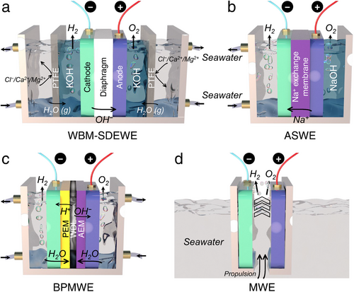
As depicted in Figure 25a, the WBM-SDEWE modifies the conventional AWE by incorporating a hydrophobic porous polytetrafluoroethylene (PTFE)-based WBM to separate seawater from concentrated KOH solution. This system utilizes the KOH solution directly in contact with both the cathode and anode. Due to varying water vapor pressures between the seawater and KOH solution, water vapor can migrate from seawater to KOH solution through the PTFE-based WBM via a liquid–gas–liquid phase transition, while effectively isolating impurity ions such as Cl−, Ca2+, and Mg2+. This innovative design (Figure 26a), inspired by self-driven phase transition processes, was successfully demonstrated by Xie et al. in their symmetrical seawater electrolysis system.[104] The micrometer-scale gas diffusion path within the PTFE-based WBM not only ensured a high rate of water migration to support H2 and O2 production but also effectively blocked impurities, preventing the precipitation of Ca(OH)2 and Mg(OH)2 and corrosion from Cl2 and oxychlorides. As shown in Figure 26b,c, this symmetrical seawater electrolysis system operated steadily for over 72-h with ≈100% Faradaic efficiency. It achieved an impressive H2 production rate of 386 L h−1 at a current density of 250 mA cm−2 for more than 3200 h, with exceptionally low energy consumption of 5 kWh Nm−3H2 (Figure 26d,e). After extensive use, minimal corrosion was observed on the electrocatalyst, and the PTFE-based WBM remained effectively dry. Therefore, this well-designed WBM-SDEWE system holds significant potential for broad application in seawater electrolysis and other complex wastewater electrolysis cases.
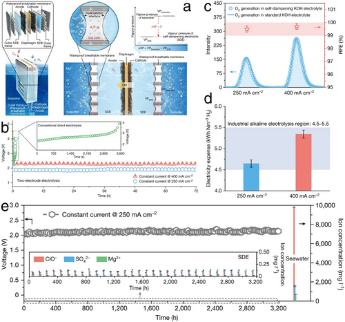
Additionally, building on the traditional architecture of AEMWE, asymmetric electrolytes are provided in the ASWE. As detailed in Figure 25b, real seawater and NaOH solution are independently supplied to the cathode and anode, respectively. A Na+ exchange membrane is utilized instead of AEM, facilitating the transfer of Na+ from the anode to the cathode while preventing the reverse movement of Cl−. This configuration effectively eliminates the competitive ClER during the anodic OER reaction. On the cathode side, by employing neutral real seawater, the formation of highly alkaline conditions and the consequent serious precipitations of Ca(OH)2 and Mg(OH)2 are successfully avoided. Inspired from this idea, Shi et al. employed this ASWE system,[105] integrating it with an electrocatalyst composed of Ni-Fe-P nanowires anchored with atomic Pt (Figure 27a). The system achieved a current density of 100 mA cm−2 at cell voltages of 1.46 and 1.5 V in simulated and real seawater at 25 °C, respectively. Remarkably, even at 80 °C in simulated seawater, the system required only a low cell voltage of 1.66 V to achieve a high current density of 400 mA cm−2 (Figure 27b). Coupled with its excellent 120-h long-term stability at a current density of 100 mA cm−2 (Figure 27c,d), this well-constructed ASWE demonstrated superior seawater electrolysis activity and stability compared to other studies. Ultimately, the calculated energy consumption led to a hydrogen cost of only 1.36 USD per kilogram, lower than that of the “Green H2” targets set by the US DOE.[67]
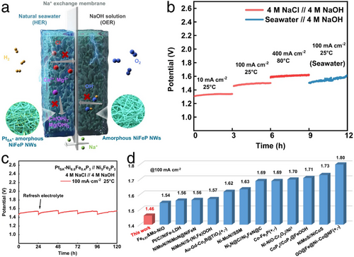
To leverage the advantages of both PEMWE and AEMWE, the integration of PEM and AEM into a BPMWE is also explored. As depicted in Figure 25c, PEM and AEM are situated respectively at the cathode and anode. When seawater is introduced, water migrates through the PEM and AEM to the water dissociation layer (WDL), where it dissociates into H+ and OH−. These ions are then selectively transported to the cathode and anode, respectively, facilitating HER and OER electrocatalysis. Notably, the accumulation of H+ at the cathode induces a local acidic environment that inhibits the precipitation of Ca(OH)2 and Mg(OH)2, while the accumulation of OH− at the anode incurs a local alkaline environment conducive to OER rather than ClER, ensuring prolonged active and stable operation of seawater electrolysis. In this case, the thickness of the PEM and AEM is critical for effective water transport to the WDL. A thinner AEM can aid the mobility of OH− to better match the H+ transfer velocity through the PEM, which typically occurs several times faster. As shown in Figure 28a–c, Mayerhöfer et al. utilized a BPMWE with a thinner AEM,[106] achieving an industrial-scale current density of 450 mA cm−2 at a cell voltage of only 2.2 V in pure water, along with 100-h long-term stability at a high current density of 2000 mA cm−2 at 80 °C (Figure 28d,e). This expertly designed BPMWE holds promise for both pure and seawater electrolysis, positioning the half-reactions of HER and OER in optimally suited pH environments to potentially reduce overall maintenance costs in practical seawater electrolysis applications.

Enhancing membrane performance is a crucial strategy to improve the activity and stability of seawater electrolyzers. Conversely, eliminating membranes in seawater electrolysis can also effectively reduce associated drawbacks such as ohmic losses while decreasing costs. A notable design, as depicted in Figure 25d, utilizes the Segré–Silberberg effect in a microfluid water electrolyzer (MWE) that operates without membranes. This method efficiently separates and collects generated H2 and O2 gases. To be specific, a seawater velocity gradient across the generated H2 or O2 molecules exerts a net inertial lift force on them toward the wall and then is counterbalanced by a force generated between the H2 or O2 molecules and the channel wall, finally stabilizing H2 and O2 gases near the cathode and anode, respectively. According to research by Hashemi's group,[107] this well-designed MWE operated effectively under high seawater flow rates, achieving water splitting at a current density of 300 mA cm−2, with a conversion efficiency exceeding 42%, and maintaining an exceptionally low H2 and O2 crossover rate of 0.4%. This MWE design ensured that precipitates at the cathode and Cl2 at the anode are swiftly removed from the device, preventing electrode coverage or corrosion, while still capturing the produced H2. Remarkably, the MWE can be manufactured using straightforward techniques, such as high-resolution 3D printing or injection molding. Therefore, when configured in cascade arrays of multiple rows and columns, this approach can readily facilitate scalable H2 production, potentially meeting industrial-scale demands.
4 Challenges and Progresses of H2 Storage and Transportation
4.1 Obstacles in H2 Storage and Transportation
The steady and industrial-scale production of green H2 represents a crucial initial step toward realizing the future hydrogen economy. Yet, to meet the diverse needs of society—from industrial applications to everyday uses—the cost-effective storage and transportation of H2 for commercial exchange or direct end-use applications (such as industrial feedstocks, urban heating, and vehicular fuel) are critically important subsequent steps.
In the aspect of H2 storage,[108, 109] key parameters such as volumetric and gravimetric density, operating temperature, the cycle life of hydrogen charge–discharge, and H2 gas filling time are closely linked with the evaluation of H2 storage technologies (Figure 29a). These technologies fall into two primary categories: physical and chemical methods, as illustrated in Figure 29b.[110] Of which, physical storage typically involves changes in the physical state of H2—this includes compressing H2 gas to increase storage pressure, liquefying H2 by lowering the temperature, and cryo-compressing H2, which combines both increasing pressure and decreasing temperature. On the other hand, chemical storage involves the use of specific materials that serve as H2 carriers, such as liquid-organic hydrogen carriers (LOHC), metal hydrides, MOF, and carbon nanotubes (CNT). Notably, H2 is mainly chemically absorbed in LOHC and metal hydrides through dissociation into hydrogen atoms, whereas MOFs, CNTs, and similar porous carbon materials utilize their extensive specific surface area and proper hydrogen binding energy for H2 adsorption.
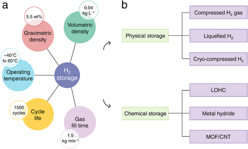
While H2 storage and transportation methods are largely consistent worldwide, differences in social and economic conditions, the scale and distance of transport, and particular uses dictate each country's strategy for managing hydrogen. For instance, some countries utilize natural geological formations such as salt caverns, aquifers, and depleted gas reservoirs as natural pressure vessels (PVs) for storing compressed H2 gas. Nonetheless, these options are not without their limitations: salt caverns often have small volumes and are sparsely distributed; aquifers pose risks of H2 leakage due to their porous nature and potential uncontrollable reactions between stored H2 and surrounding minerals; and depleted gas reservoirs may contain residual natural gas that can compromise the purity of the stored H2.[111] Consequently, artificial PVs remain a widely adopted solution globally. Currently, these artificial PVs are classified into four types as outlined in Table 4, where selecting among them often involves weighing technological advantages against cost-effectiveness, tailored to the specific field of application.[109] Generally, the expense associated with H2 storage per unit mass remains substantial, emphasizing the critical need for the development of cost-efficient, advanced pressure-bearing H2 storage solutions.
| Type | Bearable pressure [MPa] | Cost [USD kgH2−1] | Application field | |
|---|---|---|---|---|
| 1 | Steel or Al PVs | 15–30 | 240 | Industrial H2 gas |
| 2 | Glass fiber hoop-wrapped metallic PVs | 10–95 | 360 | H2 refueling station (high-pressure H2) |
| 3 | Metal liner fully-wrapped composite PVs | 30–70 | 700 | H2 tube trailer, H2 trailer, on-board H2 (low-pressure H2) |
| 4 | High-density polyethylene inner with glass or carbon fiber PVs | 30–70 | 500–1200 |
Liquefied H2 technology offers superior volumetric and gravimetric densities compared to compressed H2 gas. However, the process of liquefying H2 is energy-intensive and time-consuming, primarily because it involves cooling H2 to its extremely low evaporation temperature of −253 °C through an intricate cycle, incurring energy losses of ≈40%.[112] Despite these losses, liquefied H2 remains a viable option for medium to large-scale storage and transport via road, rail, and intercontinental shipping,[113, 114] benefiting from cost-efficient bulk transportation. As a typical case, in February 2022, the Suiso Frontier ship built by Kawasaki Heavy Industries took its first shipment of liquefied H2 from Hastings port in Australia to Kobe in Japan.[114] This ship features a tank capacity of ≈1250 m3, equivalent to ≈88 t of liquefied H2, although the actual load was only 2.6 t during this pilot project. The potential maximum delivery capacity of liquefied H2 by this ship is ≈90 times that of a typical steel-compressed H2 gas tube trailer.[115] In brief, while liquefied H2 technology presents significant economic advantages for the future, its substantial energy consumption results in a high environmental impact, exacerbated by the challenges of maintaining the cryogenic tanks at high pressure as the liquefied H2 absorbs heat and begins to evaporate.
To mitigate the rate of H2 evaporation, the cryo-compressed H2 method has been introduced, combining elements of both compressed and cryogenic H2 storage.[116] As shown in Figure 30a, this technique achieves higher volumetric and gravimetric densities than standard liquefied H2, maintaining effectiveness at pressures exceeding 15 MPa and even at relatively elevated temperatures. However, as depicted in Figure 30b, the application of excessive pressure in cryo-compressed H2 systems proves uneconomical from the view of energy consumption (in Figure 30c, the short curve under lowest pressure of 0.4 MPa represents conventional liquefied H2 processes, while the other curves represent pressure variations in cryo-compressed H2 with corresponding temperature changes). Thus, a balance between storage pressure, temperature, and energy consumption is essential in cryo-compressed H2 systems.[117] Therefore, cryo-compressed H2 vessels represent a hybrid of compressed H2 gas PVs and liquefied H2 tanks. The challenge remains to develop low-cost, high-pressure-resistant materials for these vessels, which is critical for advancing H2 storage and transportation technologies.
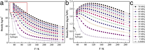
Unlike physical storage methods that involve directly compressing or cryogenically liquefying H2, chemical storage of H2 employs materials like LOHCs and metal hydrides through a hydrogenation reaction. LOHCs, which remain liquid at room temperature, facilitate straightforward hydrogenation and dehydrogenation by binding with hydrogen atoms in hydrogen-lean molecules.[118] Prominent LOHC materials include N-ethyl carbazole, methanol, dibenzyl-toluene, and toluene, which are preferred for their selective H2 storage capabilities, effectively avoiding the capture, transport, and release of CO2 and CO.[119] However, despite their reusability and manageability under ambient conditions, the current limited storage capacities of LOHCs present challenges for scaling up industrial H2 storage, especially in the forthcoming era of hydrogen energy.[120] Metal hydrides offer a safer, solid-state alternative with the potential for high volumetric H2 storage densities exceeding 0.1 kg L−1 without the need for tanks,[109] surpassing the U.S. Department of Energy's target of 0.04 kg L−1 for light-duty fuel cell vehicles as presented in Figure 29a. Among these, LiBH4 stands out with high volumetric and gravimetric H2 capacities of 0.12 kg L−1 and 18.5 wt.% (available H2 contains 13.8 wt.% in LiBH4 since the formation of LiH and free B), respectively. Nevertheless, its high dehydrogenation enthalpy (ΔH°) of 72 kJ mol−1 at 25 °C, indicative of strong metal–hydrogen bonds, restricts its dehydrogenation rate.[121] In comparison, TiFeH2 presents a lower ΔH°, yet its gravimetric H2 capacity of only 1.91 wt.%,[122] which is far lower than the H2 storage goal of gravimetric density (5.5 wt.%) as shown in Figure 29a. Therefore, since the release of H2 from metal hydrides at ambient temperatures and pressures necessitates a low value of ΔH°, the development of metal hydrides for H2 storage and transport should prioritize strategies that effectively balance the H2 storage capacity and dehydrogenation enthalpy of specific materials.[123, 124]
The advancement of chemical storage methods using porous materials with high specific surface areas is also progressing. Currently, materials such as MOFs and CNTs are demonstrating substantial potential. Specifically, MOFs are distinguished for their effective H2 interactions due to their exposed positive charge density at under-coordinated open metal sites. Modulating the positive charge density at these metal cation sites in MOFs can improve the polarization and binding with H2.[125-127] In the adsorption process, crucial considerations include a favorably low crystallographic volume at each open metal site and an optimal MOF─H binding strength. Overall, the technological advancements in both physical and chemical H2 storage and transport heavily rely on the development of new functional materials that can offer multiple advantages toward achieving higher volumetric and gravimetric H2 densities, as well as supporting cyclable H2 charging/discharging across a broad temperature range.
H2 transportation typically involves using diverse vehicles to carry H2 storage vessels or directly transferring H2 gas through pipelines. For terrestrial transport, H2 is commonly stored in compressed gas PVs or liquefied H2 tanks, which are then loaded onto trailers. Pipeline transportation offers an alternative for long-distance land delivery. For exceptionally long distances and bulk H2 transport, maritime transport using liquefied H2 tanks proves to be cost-effective. Fundamentally, whether via trailers, pipelines, or ships, the critical aspect of H2 transportation hinges on employing suitably adapted H2 storage vessels, encompassing both physical and chemical storage methods. Reflecting the advancements in H2 storage technologies, the choice of H2 transport strategies is predominantly determined by the distance involved. Consequently, Table 5 outlines the optimal H2 transport methods based on transport distance, with considerations of H2 production, storage, and transport costs, as well as H2 loss during these processes,[109, 128] all aimed at identifying the most cost-effective method for H2 transport within the hydrogen economy.
| Transport approach | Transport distance | |
|---|---|---|
| Land transport | Compressed H2 gas trailer | Short distance, <100 km |
| Liquefied H2 trailer | Medium distance, >500 km | |
| Pipeline | Long distance, <1000 km | |
| Sea transport | Liquefied H2 ship | Extra-long distance, >1000 km |
4.2 Innovations in H2 Storage and Transportation
From the insights gained in the previous chapter on physical storage, methods like compressed H2, liquefied H2, and cryo-compressed H2 storage all depend on pressure-bearing PVs that are cost-effective and robust. Notably, metal PVs, such as those made from steel or aluminum, are prone to hydrogen embrittlement, posing a risk of rupture under high pressure due to molecular permeation of H2. In contrast, fiber composite PVs, including those made with glass or carbon fiber, offer advantages in being lightweight, high-strength, and resistant to corrosion. A prime example of advanced fiber composite PVs in the automotive sector was the Toyota Mirai Type IV H2 storage system,[129, 130] which operated at a nominal pressure of 70 MPa and achieved gravimetric and volumetric densities of 5.7 wt.% and 0.0408 kg L−1, respectively. These figures surpassed the H2 storage targets set by the US DOE for light-duty fuel cell vehicles for the year 2025.[66] In 2020, Toyoda Gosei Co., Ltd. introduced a second-generation Toyota Mirai Type IV H2 storage system, incorporating more PVs to extend the vehicle's driving range to ≈850 km.[131] By 2023, Toyoda Gosei Co., Ltd. further innovated by developing a larger tank capable of holding eight times more H2 than its predecessor, accelerating the commercialization of H2 in the automotive sector.[132] Despite these advancements, the challenge remains that as PVs increase in size, the gravimetric and volumetric densities of H2 storage do not progress correspondingly. Thus, there is a pressing need to explore new materials for PV fabrication that can store more H2 in smaller volumes, achieve minimal H2 permeation rates, and avoid material embrittlement and cracking, even at low initial yield stresses.
Due to their high strength, lightweight properties, and impermeability at low temperatures, oxidized glass materials have proven advantageous for H2 storage and transportation, allowing for high-pressure resistance while requiring minimal wall thickness.[133] Recently, hollow glass microspheres (HGMs, Figure 31a,b) and glass capillary arrays (GCAs, Figure 31a,b) have emerged as prominent forms of oxidized glass used for H2 charging and discharging. The operational mechanism involves compressing H2 into the HGMs as temperatures rise. At room temperature or lower, these microspheres exhibit non-permeability to H2, thereby effectively trapping it as temperatures decrease.[134] This process facilitates the cyclic charging and discharging of H2. The gravimetric and volumetric densities of H2 storage in these systems primarily depend on the physical characteristics of the HGMs, such as wall thickness, size, composition, as well as storage temperature, and pressure. Intuitively, enhancing the wall strength of HGMs can improve H2 storage efficiency, while the storage pressure directly influences both gravimetric and volumetric densities. Balancing these densities requires careful consideration of the interplay between HGM strength and H2 storage pressure. Figure 31a illustrates the gravimetric and volumetric efficiencies of HGMs under varying pressures for different glass strengths, demonstrating their potential as high-performance, high-pressure-bearing H2 storage PVs.
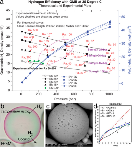
As previously discussed, H2 storage in HGMs is strongly temperature-dependent, necessitating substantial heat input during the charging and discharging processes due to the inherently low thermal conductivity of glass. To enhance H2 storage efficiency by improving heat transfer, the incorporation of metal dopants such as Mg, Fe, Co, and Zn into HGMs has proven to be advantageous. Specifically, Dalai et al. enhanced the thermal conductivity of HGMs by doping them with ZnO.[135] As presented in Figure 31c, ZnO was applied to the walls of HGMs using a flame spraying technique. When the Zn content in these hybrid HGMs (HAZn) reached 2%, they achieved an optimal H2 storage gravimetric density of 3.26 wt.% under a pressure of 10 bar at 200 °C. However, while lower Zn contents up to 2% improved the thermal conductivity and H2 storage capacity of HAZn, higher Zn concentrations resulted in uneven ZnO deposition, which obstructed the nanopores on the HGM walls, subsequently reducing the H2 storage capacity (Figure 31d). Clearly, optimizing the addition of small, thermally conductive dopants to HGMs is a promising strategy for enhancing their H2 storage gravimetric density in future applications.
Building upon the technology of oxidized glass, moreover, GCAs have been developed to enhance H2 storage capacity. Comprising hollow glass fibers, each fiber within a GCA acts as an independent PV (Figure 32a), allowing for the construction of GCAs in various sizes and shapes to accommodate diverse storage requirements.[136] Theoretically, as depicted in Figure 32b, when the ratio of the glass capillary wall thickness to its radius is less than 0.2, the H2 storage gravimetric density can significantly increase from 7 wt.% to as high as 26 wt.%, surpassing the values achieved by the Toyota Mirai Type IV H2 storage PVs. This configuration minimizes the risk of explosion since each fiber stores only a small amount of H2. Unlike other systems that depend on temperature changes, the charging and discharging processes in GCAs are controlled simply via a gate switch, simplifying H2 storage operations. Specifically, Zhevago et al. pioneered the construction of a GCA using quartz capillaries to store H2.[137] As presented in Figure 32c, one end of the GCA was sealed with a metal alloy, and the quartz capillaries were coated with a thin layer of epoxy resin, then bonded together using epoxy polymerization under UV radiation. Remarkably, this GCA, when tested under a H2 storage pressure of 171 MPa (≈1685 atm) at room temperature, achieved gravimetric and volumetric densities of 10.2 wt.% and 0.0483 kg L−1, respectively (Figure 32d,e), far exceeding those of the Toyota Mirai Type IV H2 storage PVs and the US DOE's 2025 targets for light-duty fuel cell vehicles.[66] This advancement indicates a trend toward lighter, higher-pressure bearing, and higher-density H2 storage PVs, also improving safety. With ongoing innovations in material science and the application of mature fiber composite techniques already used in Types 2–3 artificial PVs (Table 4), the future of pressure-bearing PVs appears promising for broadening the scope of H2 storage and transportation applications.
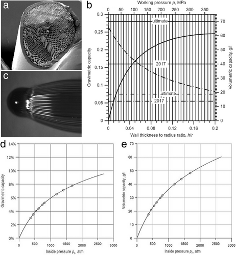
Regarding chemical H2 storage, LOHCs, and metal hydrides have been previously explored as mediums through which H2 is stored via chemical reactions. However, commonly used LOHC materials currently tend to exhibit low H2 storage capacities, while metal hydrides and porous materials face challenges in achieving both high H2 storage capacity and low dehydrogenation enthalpy (ΔH°) for H2 release. For example, LiBH4 offers a high gravimetric H2 capacity of 13.8 wt.%, but this comes at the cost of a high dehydrogenation ΔH° of 72 kJ mol−1 at room temperature,[121, 124] which hampers practical application in chemical H2 storage systems. Achieving a balance between H2 storage capacity and dehydrogenation ΔH° within a given material is crucial. The primary goal is to lower ΔH° to facilitate rapid H2 release from chemical storage carriers. Recent advancements have introduced several methods to modulate ΔH° effectively, including strategies like eutectic melting, microstructure-induced strain, and the synthesis of high entropy metal alloys. These innovative approaches represent promising directions for enhancing the practicality of chemical H2 storage technologies.
Based on the high gravimetric H2 capacity of LiBH4 and recognizing that potassium hydride (KH) enhances H2 desorption, Pal et al. explored a eutectic system, (2LiBH4−MgH2)x−(KH)1−x, demonstrating a significant reduction in melting temperature due to eutectic formation.[138] At a specific composition (x = 0.45), this system exhibited a melting temperature of only 79 °C, substantially lower than the 285 °C observed for the base LiBH4-MgH2 mixture without KH addition. This reduced melting temperature, enabled by the weakened Li─B─H bonds in molten LiBH4, enhanced H2 desorption kinetics while preserving the high H2 storage capacity of the (2LiBH4─MgH2)x─(KH)1−x. Similarly, Cho et al. found that external strain from rGO and internal Ni doping collectively enhanced the hydriding and dehydriding processes of Mg nanocrystals.[139] The high hydrogen selectivity of rGO sheets reduced the risk of explosion in Mg-based H2 storage systems, and the Mg-Ni alloying improved hydrogen adsorption and desorption. These modifications resulted in kinetic and thermodynamic improvements for H2 storage, including a reduced dehydrogenation enthalpy (ΔH°) of 66.9 kJ mol−1 compared to the original 76.3 kJ mol−1 for bulk Mg, and a high gravimetric density of 6.5 wt.% H2. Further, Witman et al. employed machine learning and statistical techniques to initially screen the stability of hydrides across 672 high entropy alloys, allowing for targeted selection based on thermodynamic properties, alloy phase stability, and density for laboratory validation.[140] Several high entropy alloys were synthesized and evaluated, with the optimal AlTiVCr alloy showing a 20 kJ mol−1 reduction in ΔH° relative to the benchmark TiVZrNbHf alloy. This resulted in significantly enhanced H2 release kinetics, evidenced by a 70-fold increase in the equilibrium vapor pressure of H2. These advanced approaches in H2 storage material development, combining theoretical predictions with experimental validation across a broad range of candidates, are crucial for advancing high-capacity H2 storage technologies.
Thanks to extensive advancements in physical H2 storage PVs and the development of chemical H2 storage materials with both high storage capacity and low dehydrogenation ΔH°, significant improvements in gravimetric and volumetric densities in H2 storage have been achieved, as detailed in Table 6. These achievements have surpassed the H2 storage targets for light-duty fuel cell vehicles set by the US DOE for 2025, thereby providing numerous practical options for H2 storage and transportation. Building on this momentum, ongoing research and improvements in the thermodynamics and kinetics of H2 storage materials continue to create new possibilities for the development of effective and practical H2 storage and transportation solutions for future use.
5 Industrial Chain Explorations for Green H2
Beginning with the green H2 generation, followed by its physical or chemical storage and transportation, and culminating in its end uses in industrial production, daily life, and vehicle operation, this hydrogen economy model can be implemented globally. An increasing number of countries and regions are engaging in the industrialization of hydrogen energy. We have listed nearly all operational green H2 projects in Table S2 (Supporting Information), organized by their year of establishment. These projects encompass not only industrial-scale green H2 production but also its storage, transportation, and application, which have been put into practical use in recent years.
In brief, based on Figure 33a,b, the establishment of green H2 companies and projects worldwide has significantly increased, particularly over the past six years, with over 10 companies or projects being launched almost every year. Most countries and regions have initiated at least one project to produce and use green H2 to address future energy challenges. Notably, Germany has deployed 26 green H2 projects, while China, the UK, and the US have each deployed nine projects. Almost all of these green H2 projects utilize electricity from renewable sources such as wind, solar, tidal, nuclear, waste heat, and biomass to electrolyze water, often using industrial wastewater or seawater. The generated green H2 is then stored, transported, and used in various industrial and social applications, including as a power source for vehicles, a heat source for the steel industry and cities, and as a raw material for producing high-value-added chemicals like methane, methanol, ammonia, and urea. In a later section, we introduce several newly representative green H2 projects to inform readers about the latest advancements in H2 energy industrialization, from production through to supply and application, thereby inspiring future developments in the hydrogen economy.
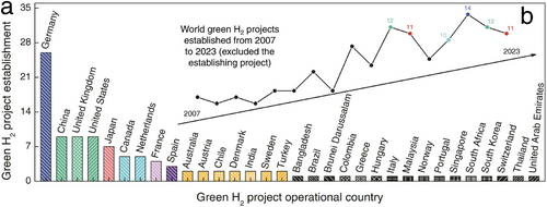
Regarding practical H2 production, supply, and application in industrial settings, the GrInHy2.0 (Wind H2) project from Germany marks a significant milestone by producing green H2 using water steam from steel production waste heat.[141-143] This project was integrated into the Salzgitter steel production process, with the high-temperature electrolyzer developed by subsidiaries of Salzgitter Flachstahl GmbH and Salzgitter Mannesmann Forschung GmbH, alongside partners Sunfire GmbH, Paul Wurth S.A., Tenova SpA, and the French Alternative Energies and Atomic Energy Commission. The water steam supplied not only serves as a water resource but also provides thermal energy to accelerate water electrolysis during H2 production. Notably, the high-temperature electrolyzer used in the GrInHy2.0 project consists of 8 modules, each comprising either 720 or 1080 solid oxide electrolyzer cells. This GrInHy2.0 prototype has a nominally AC output power of 720 kW, capable of generating 200 Nm3 h−1 of H2. By the end of 2022, the GrInHy2.0 project had operated for at least 13 000 h, producing ≈100 tons of green H2 with an electricity conversion efficiency exceeding 84%, resulting in an H2 production cost lower than 7 EUR kg−1. Additionally, the solid oxide electrolyzer cell stacks demonstrated durability with at least 20000 h, confirming their long-term operation potential, which could enable economies of scale in future H2 production. Furthermore, the direct use of H2 as a heat source during steel production was implemented in this project to reduce CO2 emissions within the steel industry. The ≈100 tons of green H2 produced has been used for steel annealing and galvanization processes.[144] In 2023, leveraging high-quality iron ore from Nunavut in Canada, the Canadian Baffinland Iron Mines Corporation formally collaborated with Salzgitter Flachstahl GmbH, aiming to achieve CO2-free steel production by 2033 using the green H2 produced from the GrInHy2.0 project.[145]
Coincidentally, in September 2023, the world earliest fossil-free H2 plant for heating steel before rolling was inaugurated (i.e., Ovako green hydrogen facility), being rated at 20 MW and can generate 3880 Nm3 of H2 per hour. Key players in this project include prominent Swedish and Nordic companies such as Volvo Group, Hitachi Energy, H2 Green Steel, and Nel Hydrogen. The green H2 produced at this facility is directly used as a heat source, replacing traditional fossil fuels in steelmaking without compromising the steel quality. Consequently, CO2 emissions from the rolling mill are virtually eliminated, reducing the carbon footprint by 80% compared to the global average.[146, 147] This pioneering use of green H2 as a heat source in the steel industry holds promise for global replication and adoption at other steel mills. The successful deployment of H2 in the steel industry in these projects signifies a burgeoning “hydrogen rush,” emphasizing H2’s potential as a future energy source.
Moreover, at the end of 2023, the world's largest green H2 production project, the Sinopec (Xinjiang Kuqa) green hydrogen pilot project, was established, led by Sinopec's New Star Company. With a substantial investment of 470.77 million dollars, this monumental project became the largest solar-to-hydrogen initiative globally and the first in China to feature a photovoltaic power generation complex with an installed capacity of 300 MW and an annual power generation of 618 million kWh. The comprehensive project infrastructure includes power transmission and transformation lines, facilities for water electrolysis H2 production, a spherical H2 storage tank, H2 transportation, and necessary auxiliaries. Utilizing renewable energy, it minimized the carbon footprint during green H2 production, achieving a large-scale annual production capacity of 20 000 tons. The project also accomplished H2 storage and transportation capacities of 210 000 Nm3 and 28 000 Nm3 h−1, respectively.[148] Then, the green H2 produced is directly supplied to Sinopec's Tahe Refining and Chemical Company to replace grey H2 generated from traditional fossil fuel-based electricity. This initiative is expected to reduce CO2 emissions by 485 000 tons annually, contribute an average of 20.4 million dollars to the local GDP, and generate 2.82 million dollars in tax revenue.[149, 150] This project has successfully provided a comprehensive model that integrates electricity generation from renewable sources, electrical transmission, green H2 production, H2 storage, transportation, and application. This fully operational model represents a significant expansion of H2 energy industrialization and serves as a benchmark for developing a hydrogen economy.
Regarding green H2 in social and urban life, the H100 Fife project is a notable success. This project launched the world's first H2 gas network in Fife, UK. Powered by clean offshore wind energy, the generated green H2 currently supplies ≈300 households through the H2 gas network, with free provision of H2 boilers and appliances. As a result, green H2 is gradually replacing conventional fossil fuels like natural gas for central heating and home cooking, supporting future low-carbon policy decisions. Additionally, the H100 Fife project secured an investment of 32 million Great British Pounds, creating numerous employment opportunities for local residents and businesses while simultaneously reducing annual CO2 emissions by 2208 kg. If this green H2 project successfully expands across the entire UK, it could potentially avoid ≈37% of CO2 emissions.[151] This emerging technology holds the promise of helping the UK transition from fossil fuels to a more sustainable hydrogen economy, utilizing existing natural gas infrastructure to power other heavy industries and transportation sectors.
The Energy Observer is an exploration ship committed to investigating various ecosystems and energy sources around the world.[152] Since its launch in 2017, the Energy Observer has navigated to locations including France, the Mediterranean, Northern Europe, the Atlantic, the Pacific, Asia, Africa, and North America, visiting over 80 cities. These explorations have been sustained by a continuous supply of solar energy. Aboard the ship, solar energy is primarily converted into electricity and stored in the form of H2, which powers the living quarters, boat systems, and propulsion, even under cloudy conditions. The vessel is equipped with 202 m2 of bifacial solar panels on the roof, stern, and sides. These panels capture both direct sunlight and light reflected from the water and the vessel's hull, generating 33 kWP (the power produced by the solar panels under standardized solar radiation of 1000 W m−2 and a temperature of 25 °C), ensuring a sustainable energy cycle. Undoubtedly, the Energy Observer project is a successful off-grid energy experiment, supported by the energy bond of H2, demonstrating that living and vehicle facilities powered by H2 are fully functional. However, these facilities would be even more convenient if integrated into a H2 gas network.
6 Life Cycle Assessments of Green H2
At this stage, the advantages and industrial applications of green H2 across various sectors were explicitly presented. Furthermore, evaluating the climate change impacts of green H2 throughout its entire life cycle, from raw material extraction to usage and disposal (cradle-to-grave, Figure 34a), is essential for determining its environmental benefits. This assessment is important for identifying opportunities for environmental improvements in future developments. Life cycle assessment (LCA) is a modeling tool commonly used to quantify the potential environmental impacts of products and processes.
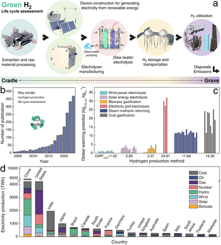
With regard to H2 production, this section reviews and discusses reported LCA results for green H2 production, focusing specifically on its global warming potential (GWP, kgCO2 eq kgH2−1). Simultaneously, we provided GWP comparisons for H2 produced through traditional methods. Notably, during the usage phase of H2, GWP calculations are excluded due to the zero emissions of CO2. Instead, GWP arises primarily from the mining and extraction of raw materials, the manufacturing and operation of H2 production equipment, as well as the storage and transportation processes. As shown in Figure 34b, LCA studies on H2 production have increased exponentially in recent years. Based on typical LCA studies of grey, blue, and green H2.[153-170] We compared the global warming impacts for different technologies, including wind power, solar energy, or electricity grid-powered electrolysis, biomass or coal gasification, and steam methane reforming. Given the slight variations in reported GWP values, an average was calculated for each H2 production technology to provide a more comprehensive comparison.
As shown in Figure 34c, H2 produced from renewable wind power exhibits the lowest average GWP of 1.02 kgCO2 eq kgH2−1. Similarly, H2 generated via solar energy electrolysis and biomass gasification also maintains low average GWP values of 2.80 and 2.37 kgCO2 eq kgH2−1, respectively. On the contrary, H2 derived from non-renewable sources, such as electricity grid electrolysis, steam methane reforming, and coal gasification, shows substantially higher environmental impacts with GWP values of 29.81, 11.68, and 19.26 kgCO2 eq kgH2−1, respectively. The minor CO2 emissions from producing green H2 through wind and solar energy electrolysis predominantly arise from the manufacturing processes of wind turbines and solar photovoltaic modules. The reduced GWP observed in biomass gasification can be linked to carbon capture during the production phase, though it may also lead to other environmental issues such as acidification, eutrophication, and the potential for forming photochemical oxidants. Notably, while steam methane reforming to produce H2 relies on non-renewable resources, its advanced processing techniques result in lower CO2 emissions compared to coal gasification and electricity grid electrolysis. Although the latter is currently powered primarily by high-pollution energy sources (e.g., in Figure 34d, most countries produced electricity in 2023 depended mainly still on fossil fuels, contributing the high GWP when generate H2 directly using local electricity grid),[171] it holds future promise as renewable and nuclear energies increasingly become the primary sources of power for the electricity grid.
In brief, the H2 production using renewable energy sources exhibited a 76% to 94.7% reduction in GWP compared to conventional methods such as steam methane reforming or coal gasification. This substantial decrease emphasizes the shifting trends toward the industrialization of hydrogen energy, increasingly oriented toward low-emission H2 production. This also aligns well with the recent global establishment of green H2 plants, which, as detailed in Table S2 (Supporting Information), are all based on renewable energy utilization. Clearly, the hydrogen energy industry has reached a significant level of maturity, with numerous facilities worldwide dedicated to green H2 production, storage, transportation, and application. These facilities are expanding in both scale and scope, covering a wide range of applications. Encouragingly, the advanced electrocatalysts and electrolyzers discussed in this review, along with improved HER processes (such as HER coupled with organic oxidation reactions) and innovations in H2 storage and transportation, can be seamlessly integrated into both existing and emerging green H2 facilities. This integration paves the way for further advancements in the hydrogen economy.
7 Concluding Remarks and Outlooks
-
Although many designs for HER and seawater HER electrocatalysts are promising, few integrate multiple key attributes such as cost-effectiveness, self-supporting structures, hydrophilicity, mechanical robustness, and intrinsic electrochemical stability. Additionally, scalable designs are crucial to meet the high demands of industrial H2 production. Therefore, developing multifunctional HER and seawater HER electrocatalysts remains critical (e.g., transition metal-based, self-supported, and self-wetting nano or atomic electrocatalysts with surface protection). Similarly, all-in-one electrocatalysts for counter OER or organic oxidation reactions are essential to minimize adverse effects during water electrolysis, particularly the competitive ClER in seawater electrolysis.
-
Machine learning technologies offer tremendous potential in catalyst design by accurately predicting activity, stability, and selectivity, revealing hidden correlations within large datasets, and elucidating structure–activity relationships and reaction mechanisms. This approach significantly reduces design cycles and associated costs. Typically, a machine learning workflow consists of three key components: data, model, and application. In the data phase, input features include structural properties, chemical properties, physics-informed descriptors, and experimental parameters. These inputs generate output targets such as DFT-calculated free energies (e.g., H*, OOH, Cl) and experimentally measured performances (e.g., activity, stability, selectivity). In the model phase, selectivity forecasting serves as an illustrative example. For instance, OER selectivity (representing the generation ratio of O2 and Cl2 during seawater electrolysis) can be treated as labeled data for classification and regression tasks. By employing Shapley Additive Explanations (SHAP), the model can estimate how catalytic selectivity is influenced by structural or chemical properties. Once promising electrocatalysts are identified through screening, small-scale experimental validation can be conducted to accurately synthesize and verify the catalysts, thereby accelerating the discovery of high-performance materials.
-
Still, research on seawater HER constitutes less than 5% of total HER publications. Most advanced seawater HER research relies on simulated rather than actual seawater, often neglecting the variable conditions of natural environments. Future studies should prioritize developing efficient and durable seawater electrolysis systems that can operate in natural seawater under harsh conditions (e.g., lower or higher temperatures, hypersalinity, or impurity-rich environments) for green H2 production.
-
Similarly, although the seawater electrolyzers discussed in this review have been adapted from conventional water electrolyzers to suit seawater environments, a fully integrated seawater electrolyzer with a comprehensive set of superior qualities remains elusive. Future developments should aim for an ingenious seawater electrolyzer with features such as rapid ion transport in membranes, low gas crossover rates, anti-precipitation, anti-corrosion, and anti-fouling.
-
In terms of H2 storage and transportation, advanced material innovations such as barely oxidized glass (e.g., HGM and GCA applications) remain limited compared to conventional PVs mainly made of metals. To improve the pressure-bearing capabilities of PVs at a lower cost, mature fiber composite techniques (e.g., glass/carbon fiber hoop/fully wrapping) need to be applied in PV fabrication using oxidized glass or other next-generation advanced materials.
-
Given the high modularity of the green H2 industry, integrating innovative electrocatalysts, electrolyzers, and H2 storage PVs into existing green H2 systems is relatively straightforward, requiring only partial substitutions rather than an overall structural transition. However, reducing costs and enabling large-scale fabrication of these components remains a priority. Throughout the entire process of green H2 production, supply, and application processes, government policies should ensure the sustainability of terrestrial and marine ecosystems while closely monitoring environmental footprints.
This review of the challenges and emerging trends in the industrialization of hydrogen energy aims to provide readers with a comprehensive understanding of the current state of hydrogen energy development. By exploring its future potential, this discussion seeks to inspire new perspectives and strategies to further advance the hydrogen economy.
Acknowledgements
This work was supported by research grants of the NRF (2023R1A2C2003823, RS-2024-00405818) funded by the National Research Foundation under the Ministry of Science, ICT & Future, Korea.
Conflict of Interest
The authors declare no conflict of interest.
Author Contributions
S.X. and P.Z. contributed equally to this work. S.X. dealt with data curation, formal analysis, investigation, methodology, software, validation, visualization, and writing original draft. P.Z. dealt with data curation, formal analysis, investigation, methodology, software, validation, visualization, and writing original draft. L.L. dealt with conceptualization, project administration, supervision, validation, and writing review and editing. M.W.M. dealt with conceptualization, project administration, supervision, validation, and writing review and editing. C.-H.C. dealt with conceptualization, project administration, supervision, validation, and writing review and editing. H.L. dealt with conceptualization, project administration, supervision, validation, and writing review and editing. J.Y.L. dealt with conceptualization, project administration, supervision, validation, and writing review and editing. P.J.Y. dealt with conceptualization, funding acquisition, project administration, supervision, validation, and writing review and editing.
Biographies

Shiyu Xu is a postdoctoral researcher at the School of Chemical Engineering at Sungkyunkwan University (SKKU) in the Republic of Korea. He received his Ph.D. (2023) degree from the School of Chemical Engineering at SKKU, where he was supervised by Prof. Pil J. Yoo. His research interests primarily focus on renewable energy developments and the construction of nanomaterials mainly for electrocatalysis and rechargeable battery.

Peng Zhang is a current Ph.D. candidate (2021 to present) in Prof. Pil J. Yoo's research group at the School of Chemical Engineering, Sungkyunkwan University (SKKU), Republic of Korea. His primary research focuses on energy conversion and the synthesis and investigation of novel electrocatalysis.

Lei Li received his Ph.D. (2009) degree from Fuzhou University in China. He currently serves as a professor at Jiaxing University. He was selected for the high-level leader in Zhejiang provincial universities, “Nanhu Scholar” chair professor, and named among the world's top 2% most-cited scientists 2020 by Stanford University. His research focuses on industrial catalysis for energy and environmental applications, including heterogeneous and electrocatalytic processes for H2 production and CO2 conversion/utilization, as well as catalytic degradation for environmental pollutants. He has published more than 50 papers on high-impact journals such as ACS Nano, Adv. Funct. Mater. etc.

Myoung-Woon Moon is a principal research scientist of the Extreme Materials Research Center at KIST and an adjunct professor of the School of Chemical Engineering at SKKU in the Republic of Korea. He earned his B.S. (1998), M.S. (2000), and Ph.D. (2004) degrees from Seoul National University in Materials Science and Engineering. He has worked as a postdoctoral associate of the School of Engineering and Applied Sciences at Harvard University before joining KIST in 2007. He is currently interested in nano/micro-structuring on polymeric and metallic surfaces, which can be applied for environmental protection from air or water pollutants as well as for clean energy applications.

Chan-Hwa Chung is a professor of the School of Chemical Engineering at Sungkyunkwan University (SKKU) in the Republic of Korea. He received his B.S. (1988) degree from Yonsei University, and M.S. (1990) and Ph.D. (1995) degrees from the Department of Chemical Engineering at Seoul National University (SNU). After holding a postdoc position (1995–1998) at the University of California, Santa Barbara (UCSB), he has joined SKKU (1999) as a faculty, and currently, he is a director of the Global Research Center for e-Chem Meditronic Systems in SKKU. He also served as the Adjunct Professor at the University of New Mexico (UNM), NM, USA (2005–2007). His research interests primarily focus on electrochemical devices and processes such as electrochemical sensors, batteries, supercapacitors, capacitive deionization, and electrochemical CO2 reduction.

Hao Li received his Ph.D. (2021) degree from the Department of Chemistry at Sungkyunkwan University (SKKU), Korea, under the supervision of Prof. Jin Yong Lee. Following his doctoral studies, he was selected for the prestigious “SKKU Science Fellow” postdoctoral program. Currently, he serves as an associate professor at the Beijing University of Chemical Technology (BUCT). His research focuses on electrochemical catalysis, protein misfolding, and artificial-related drug and material design. He has published more than 40 papers, with a majority appearing in top-tier international journals like Chem. Rev., JACS, Angew. Chem. Int. Ed. etc.

Jin Yong Lee graduated and obtained a Ph.D. (Chemistry) from POSTECH supervised by Prof. Kwang S. Kim in 1997. He worked with Prof. David Chandler in the University of California at Berkeley as a postdoc and with Prof. Shaul Mukamel in the University of Rochester as a research associate. He was appointed as an assistant professor at Chonnam National University in 2002. He moved to Sungkyunkwan University in 2005, where he promoted to professor in 2012. His research interest includes understanding the molecular mechanism of photocatalysts, electrocatalysts, batteries, OLEDs, spin/electron transport, and excited state dynamics, and machine learning for materials design.

Pil Jin Yoo is a professor of the School of Chemical Engineering at Sungkyunkwan University (SKKU) in the Republic of Korea. He received his B.S. (1998), M.S. (2000), and Ph.D. (2004) degrees from the Department of Chemical Engineering from Seoul National University (SNU). He has worked as a postdoctoral associate in the Department of Chemical Engineering of Massachusetts Institute of Technology (MIT), then he joined the faculty of SKKU in 2007. His research expertise currently includes interfacial manipulation of functionalized thin films using multiscale architecting methods and organic/inorganic hybridization for next-generation energy devices and environmental applications. Currently, he also serves as the vice president of university planning and coordination of SKKU.


