Osmotically Delaminated Silicate Nanosheet-Coated NCM for Ultra-Stable Li+ Storage and Chemical Stability Toward Long-Term Air Exposure
Abstract
To ensure the safety and performance of lithium-ion batteries (LIBs), a rational design and optimization of suitable cathode materials are crucial. Lithium nickel cobalt manganese oxides (NCM) represent one of the most popular cathode materials for commercial LIBs. However, they are limited by several critical issues, such as transition metal dissolution, formation of an unstable cathode-electrolyte interphase (CEI) layer, chemical instability upon air exposure, and mechanical instability. In this work, coating fabricated by self-assembly of osmotically delaminated sodium fluorohectorite (Hec) nanosheets onto NCM (Hec-NCM) in a simple and technically benign aqueous wet-coating process is reported first. Complete wrapping of NCM by high aspect ratio (>10 000) nanosheets is enabled through an electrostatic attraction between Hec nanosheets and NCM as well as by the superior mechanical flexibility of Hec nanosheets. The coating significantly suppresses mechanical degradation while forming a multi-functional CEI layer. Consequently, Hec-NCM delivers outstanding capacity retention for 300 cycles. Furthermore, due to the exceptional gas barrier properties of the few-layer Hec-coating, the electrochemical performance of Hec-NCM is maintained even after 6 months of exposure to the ambient atmosphere. These findings suggest a new direction of significantly improving the long-term stability and activity of cathode materials by creating an artificial CEI layer.
1 Introduction
Since their first commercialization in the 1990s, lithium-ion batteries (LIBs) have been employed as sustainable high-energy systems in various applications ranging from smartphones,[1] laptops,[2] electric vehicles,[3] to electric grids.[4] Although substantial progress has been made in the investigation of advanced cathode materials, with a transition from lithium cobalt oxide[5] to high Ni-rich/Mn-rich cathodes,[6] incorporation into commercial LIBs required sophisticated optimization to improve cycling stability. Among several cathode materials, lithium nickel cobalt manganese oxide (NCM) has attracted significant attention due to its superior electrochemical performance, e.g., high specific capacity and relatively long cycle life.[7] However, several issues are still present for applying Ni- or Li-rich NCM for more advanced and long-term applications (such as smart electric grids and transportation): 1) Transition metal dissolution from NCM takes place during cycling, which causes catalytic electrolyte decomposition and the formation of an unstable cathode–electrolyte interphase (CEI) layer. Transition metal migration to the anode can also lead to a destabilization of its solid electrolyte interphase (SEI), as well as a promotion of Li dendrite growth and result in safety hazard issues.[8] 2) Since NCM, like other lithiated layered compounds, is hygroscopic to some degree, exposure of NCM to humidity/air leads to the formation of electrochemically reactive and electrically insulating surface layers (mostly Li2CO3 and LiOH), which quickly and significantly degrades the capacity by up to 30%.[9] 3) Mechanical cracking of large secondary NCM particles with concomitant loss of contact between small primary NCM particles during cycling triggers accelerated capacity decay.[7] Therefore, a simple, straightforward, and rational strategy to address these issues for NCM is indispensable.
To mitigate these issues, various strategies to improve the electrochemical performance of NCM were devised and executed. For instance, both high valence elements (such as Ti4+) and low valence elements (such as Na+ and K+) were doped into/onto the cathode particles, which mitigates cation mixing and suppresses transition metal dissolution.[6, 10] Although some alleviation is evident by doping, it fails to hamper transition metal dissolution completely. Furthermore, it does not necessarily address the structural integrity and thermal stability of NCM during cycling, which leads to rapid capacity fading. The underlying cause is the inherently unstable nature of the CEI produced by doping, which fails to stabilize and ultimately passivate the material against degradation. Instead, it can even hamper the performance by lowering the effective capacity of binding lithium.[11]
Another strategy to improve the mechanical, thermal, and chemical stability of NCM is a coating of the secondary particle surface with various inorganic colloids, for instance, Li3PO4,[12] Al2O3,[13] PPy-LiAlO2,[14] LiTiO3,[15] SiO2,[16] and LixSiyOz.[17] Unfortunately, when applying the coating via affordable precipitation methods, the coatings turn out to be inhomogeneous and become relatively thick (up to 300 nm[13]). This can significantly increase the resistivity for ionic and electronic transport and thus, in turn, increase the cathode polarization losses. Alternatively, thin coatings of uniform thickness can be fabricated by physical deposition methods like atomic layer deposition, but these are rather costly. Therefore, solution-based and thus affordable coating processes that allow for a homogeneous and nanometer-thin surface coverage while offering stable adhesion to NCM particles are highly desirable.
In this work, we have coated osmotically delaminated sodium fluorohectorite (Hec, [Na0.5]inter[Mg2.5Li0.5]oct[Si4]tetO10F2) nanosheets onto commercial secondary NCM (Hec-NCM). This approach allows to simultaneously achieve a homogeneous, few nanometer-thick coating and a uniform coverage of the entire particle surface. The Hec nanosheets help to retain the electrochemical performance of NCM even after a few hundred cycles, while their high aspect ratio (≈10 000)[18] and flexibility[19] allow them to wrap the NCM secondary particle completely, thus providing additional mechanical, thermal and chemical stability. Attributed to the nanoscale coating thickness of these thin inorganic nanosheets (≈1 nm), Hec-NCM achieved ultra-stable electrochemical performance (a capacity decay of 0.11% per cycle at 1.0 C). Furthermore, as Hec nanosheets offer a diffusion barrier not only for the electrolyte but also for water vapor and CO2, Hec-NCM, after 6 months of exposure to the ambient atmosphere, still exhibits an excellent electrochemical performance (70% capacity retention after 250 cycles at 1.0 C). This conservation of capacity, even in the ambient atmosphere, can be ascribed to the unique chemical, structural, and physical characteristics that Hec nanosheets offer.
2 Results and Discussion
2.1 Fabrication and Analysis of Hec-NCM
The fabrication of Hec-NCM is based on a simple, industrially benign, aqueous, and therefore sustainable process (Figure 1a). Briefly, the commercially available synthetic sodium fluorohectorite (Hec) is delaminated into nanosheets of 1 nm thickness by a spontaneous, thermodynamically allowed 1D dissolution, which was historically referred to as osmotic swelling.[18, 20] This type of delamination does not require any additional mechanical or thermal driving force.[20] Instead, simply immersing Hec into distilled water triggers the complete delamination into negatively charged monolayers. The nanosheet fabrication is therefore applicable for mass production.[21]
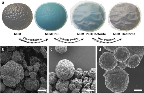
The morphological evolution from NCM (detailed composition see experimental part) to Hec-NCM is followed via scanning electron microscopy (SEM) images of NCM, polyethyleneimine (PEI)-coated NCM, and Hec-NCM (Figure 1b–d). The SEM image of NCM (Figure 1b) shows the typical spherical secondary particle and no noticeable morphological alteration after the introduction of PEI (Figure 1c). To achieve a stable coating, the surface charge (ζ ≈ −25 mV) of the pristine NCM is converted from negative to positive by adding a cationic polyelectrolyte (PEI) as a binder. The addition of PEI yields a positive surface charge (ζ ≈ 30 mV) of the secondary particles that are capable of electrostatically attracting the negatively charged Hec nanosheets (ζ ≈ −20 mV). This Coulomb attraction assures a uniform nanosheet coating onto the PEI-covered surface of NCM. Subsequently, PEI is removed through calcination at two alternative temperatures of 450 or 600 °C, while the Hec nanosheet remains attached to the surface of NCM. As the synthetic Hec is fully fluorinated, the nanosheets are thermally stable up to 800 °C. Thermogravimetric analysis (TGA) (Figure S1, Supporting Information) shows that at 450 °C, most of the polymer (90%) is decomposed, while at 600 °C, the remaining 10% can also be removed. SEM images of Hec-NCM (Figure 1d) indicate the wrapping of the NCM secondary particles with Hec nanosheets. The nanometer-thin clay sheets are apparently flexible enough to form a continuous film on the NCM particles by partially overlapping individual nanosheets. The uniform coating formed by Hec nanosheets is further confirmed by energy-dispersive X-ray analysis (EDX) (Figure S2, Supporting Information). Element mapping of two of the main constituents of the Hec nanosheets, Si and Mg, show a uniform coverage on the surface of the cathode particles after the calcination step, suggesting a complete and continuous surface coating of NCM.
Based on inductively coupled plasma optical emission spectrometry (ICP-OES) analysis, we attempted to estimate the thickness of the coating based on the Ni/Mg ratio in the sample. For the calculations, we utilized the fact that Ni is only found in the cathode active material, whereas Mg is only found in the Hec nanosheet coating. Assuming a smooth, spherical surface (see Supporting Information for details of the simplified geometrical model applied) allows the estimation that the coating consists of only a few nanosheets, amounting to a coating thickness of less than 5 nm.
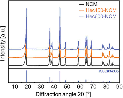
X-ray diffraction (XRD) patterns (Figure 2) were recorded to probe possible structural alterations or secondary phase formations during the calcination process. Here, two different samples of Hec-NCM that underwent different heat treatments (at 450 and 600 °C) are denoted as Hec450-NCM and Hec600-NCM, respectively. All patterns represent the typical features of LiNi0.33Mn0.33Co0.33O2, which crystallizes in the α-NaFeO2 structure type with the space group .[33, 34] All reflections can be indexed and good fits were obtained by full pattern Le Bail refinement (Figure S3, Table S1, Supporting Information). Following the literature data on the material, no impurity phases could be found before or after the temperature treatments. Moreover, according to the refinements, the annealing did not trigger a coarsening of primary crystallites. The absence of other reflexes not associated with NCM indicates that it does not undergo a reconstruction of the crystal structure. The refined c/a-ratios (consistently above 4.97[22]) indicated a well-ordered layered structure. The c/a-ratio increased only marginally during calcination from 4.971 (NCM) to 4.976 (Hec600-NCM). Due to turbostratic stacking and the limitation to very few nanosheets in the coating, it does not show up in the diffraction pattern. This observation is in line with previous reports of nanometer-thin coatings for NCM materials that were also not visible in the diffraction pattern.[23] The average crystallite size was calculated based on the Scherrer's equation to be 413 ± 23, 423 ± 27, and 410 ± 29 Å for NCM, Hec450-NCM, and Hec600-NCM, respectively indicating no significant changes in the crystallite size during the coating procedure.
2.2 Electrochemical Performance of Hec-NCM
Both the electrochemical characteristics and performance of NCM and Hec-NCM were evaluated and compared. Cyclic voltammetry (CV) curves of NCM, Hec450-NCM, and Hec600-NCM were recorded for three cycles at a scan rate of 0.1 mV s−1 (Figure 3a) and turned out to be in line with published, typical CV curves of NCM.[24] In line with other studies on cathode coatings,[25] half-cell tests were employed to explore the intrinsic electrochemical properties of this new synthetic CEI material.

As observed previously,[24] the anodic peak in the 2nd and 3rd cycles was shifted to lower voltages compared to the 1st cycle. The initial irreversible capacity was further evaluated based on the galvanostatic charge and discharge profile (Figure 3b). The initial coulombic efficiency of NCM, Hec450-NCM, and Hec600-NCM was 85.9%, 87.3%, and 80.5%. The overshooting of the potential observed for pristine, uncoated NCM is a well-known phenomenon. It has been ascribed to the formation of a Li2CO3 layer being formed on the surface of NMC cathode materials when exposed to moist air.[26] In line with this view and as will be discussed in more detail in Section 2.5 the overshooting is substantially reduced by the Hec nanosheet coatings as it represents an efficient gas barrier that hampers migration of water vapor and CO2 into the coated cathode material and consequently diminishes the overshooting a great deal.
The charge and discharge behavior of Hec450-NCM and Hec600-NCM is investigated by galvanostatic voltage profiles (Figure 3c,d), where the discharge capacity remains similar up to the 10th cycle, but some capacity loss occurs after the 50th cycle. Nevertheless, compared with Hec450-NCM and pristine NCM (Figure 3c), Hec600-NCM exhibits significantly less capacity decay. The capacity retention characteristics in terms of absolute capacity (Figure 3e) and relative capacity (Figure 3f) of NCM, Hec450-NCM, and Hec600-NCM further illustrate the beneficial impact of the Hec coating. As the electrochemical performance of the commercial, uncoated NCM is not modified at all by applying the carbon-coated Al foil, it becomes evident by comparing our measurements with published results on NCM on non-coated Al foil,[27] the substantially improved electrochemical performance may solely be attributed to the Hec nanosheet coating.
Although NCM exhibits higher reversible capacity in the initial cycle compared with Hec450-NCM and Hec600-NCM, the capacity of NCM after 50 cycles at 1.0 C (105.8 mAh g−1) is comparable to that of Hec450-NCM (102.9 mAh g−1) and Hec600-NCM (109.4 mAh g−1), as NCM shows a much steeper capacity fade. Moreover, a slight but significant initial capacity increase is visible for pristine, uncoated NCM (Figure 3e), which is ascribed to the activation, including electrolyte wetting and formation of CEI, not to be completed in the formation cycle applied.[28] In line with this view, once the Hec nanosheet coating is introduced as synthetic CEI, the initial capacity increase is substantially diminished, indicating a stable synthetic CEI formation prior to cycling. When compared in terms of relative capacity retention (based on the capacity at each cycle divided by the initial capacity) (Figure 3f), NCM exhibits a much lower relative capacity retention after 50 Cycles (80.7%) than Hec450-NCM (88.4%) and Hec600-NCM (96.6%). The relative capacity fading of Hec600-NCM (−3.4%) is only 18% of the relative capacity fading of NCM (−19.3%), thus reducing the loss of capacity by more than 80%. The long-term stability of Hec600-NCM was probed over 300 cycles, with a superior capacity decay of as little as 0.11% per cycle (Figure 3g).
2.3 Electrochemical Analysis of Hec-NCM
To understand the effect of the synthetic fluorohectorite nanosheets on the electrode resistance and Li+ diffusivity, electrochemical impedance spectroscopy (EIS),[29] as well as galvanostatic intermittent titration techniques (GITT), were applied for NCM and Hec600-NCM. The Nyquist plots of two cells (NCM and Hec600-NCM) after initial precycling (five galvanostatic cycles with 0.1 C, related to the theoretical cell capacity based on electrode weight, see experimental part) are compared in Figure 4a, showing similar characteristics in the considered frequency range (10 mHz to 100 kHz). Two clearly separated half-circles are visible, while the second one merges into an ascending branch toward low frequencies. Interestingly, the magnitude of the two semicircles strongly differs when comparing the two cells. The high-frequency semicircle is significantly larger for Hec600-NCM, while the low-frequency semicircle is significantly larger for NCM. Nevertheless, the overall polarization contribution of the two semicircles is in the same range for both cells (≈55 Ω), considering the real part of the impedance. To allow for a better understanding and comparison of the impedance data, a Distribution of Relaxation Times (DRT) analysis was conducted, which is a widely used method for investigating kinetic loss processes in the context of battery research.[29, 30] The DRT analysis enables the assignment of single polarization contributions hi to distinct time constants τi, resulting in the distribution function h(τ). Hence, it offers a better separation of overlapping processes than the Nyquist plot (Figure 4b). Since peaks with very low polarization can be attributed to noise or artifacts resulting from the DRT computation algorithm,[30] we focus on three main peaks or groups of peaks, respectively, labeled A to C ranging from high to low time constants. When comparing the two cells, the two peaks with the highest time constants (A) do not differ significantly and can both be assigned to solid-state diffusion in the active material particles, which is in accordance with the literature.[29, 30] The occurrence of multiple peaks with decreasing magnitude toward lower time constants is typical for diffusion effects.[30] Nevertheless, it should be stated that solid-state diffusion is not completely covered in the chosen frequency range of the measurement. Hence, this process is depicted only partly in the DRT. The most prominent peak (B) is located at a time constant of ≈10 s and corresponds to the second semicircle in the Nyquist plot. This peak can presumably be assigned to the charge transfer reaction.[30] The third main contribution (C) appears in the range of 5 × 10⁻⁶ and 3 × 10⁻⁴ s and is composed of at least two broadly distributed peaks for both cells. As indicated by the time constants, we attribute C to losses at interfaces like particle-to-particle or particle-to-current collector,[29, 31] transport across an interphase layer (CEI),[30] or the lithium counter-electrode.[30, 31] Of course, a superposition and overlap of multiple of these effects could also be possible.
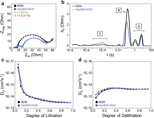
GITT curves of NCM and Hec600-NCM were examined in the lithiated (Figure 4c) and delithiated state (Figure 4d), where NCM and Hec600-NCM showed comparable Li+ diffusivity, with Hec600-NCM showing a slightly slower ionic transport. The calculated mean Li+ diffusion coefficient for NCM is 2.01 × 10⁻¹⁴ cm2 s−1 during lithiation and 3.07 × 10⁻¹⁴ cm2 s−1 during delithiation. The calculated mean Li+ diffusion coefficient for Hec600-NCM is 1.86 × 10⁻¹⁴ cm2 s−1 during lithiation and 2.53 × 10⁻¹⁴ cm2 s−1 during delithiation. This explains the slightly lower reversible capacity of Hec600-NCM compared with NCM during initial cycles (Figure 3e), where electrically insulating Hec nanosheets marginally impede facile Li+ transport.
2.4 Postmortem Analysis of Hec-NCM
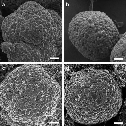
The impact of the Hec nanosheet coating was further investigated by postmortem analysis of the electrode morphology and chemical composition. The cycled coin cells, which were run at 1.0 C, were disassembled and washed with dimethyl carbonate (DMC) to remove residual impurities. Ex situ SEM analysis was employed to compare the pristine NCM (Figure 5a,c) and Hec-coated NCM (Figure 5b,d). Comparing the two samples after 50 cycles, more agglomeration/growth of primary particles became apparent for pristine NCM, whereas Hec-coated NCM retained its structural integrity without any noticeable morphology change. This suggests that an artificial CEI coating is capable of assuring the overall structural integrity of the electrode material even after extended cycling at a relatively high C-rate.
2.5 Chemical Stability and Sustained Electrochemical Performance of Hec-NCM Upon Long-Term Air Exposure
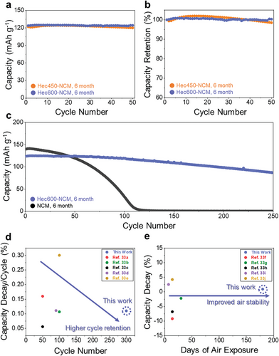
Coatings of large aspect ratio nanosheets have long been established as barrier materials for gas diffusion due to their ability to produce a tortuous path.[21, 32] Therefore, we expected a certain improvement in storage stability with the Hec coating as an additional benefit to the electrochemical performance. NCM, Hec450-NCM, and Hec600-NCM electrodes were therefore exposed to ambient conditions for 6 months, and their electrochemical performance was compared. The capacity retention characteristics in terms of total capacity (Figure 6a) and relative capacity (Figure 6b) of Hec450-NCM and Hec600-NCM show that both Hec450-NCM and Hec600-NCM retain 98.5% and 100% of their capacity. This indicates that the coating efficiently protected the cathode material from detrimental atmospheric components like water vapor or CO2. The enhanced air stability by the coating is further stressed when comparing the long-term cycling stability of NCM and Hec600-NCM after both were stored for 6 months in the ambient atmosphere. For aged Hec600-NCM, ≈70% of the capacity was retained after 250 cycles, while aged NCM showed a rapid capacity decay and retained only a negligible capacity after 250 cycles (Figure 6c). Hec nanosheet coatings clearly prove to be an effective means of realizing higher chemical stability and shelf life of NCM, rendering special storage environments unnecessary. The environmental stabilization by means of Hec-coating becomes even more evident by comparing electrochemical performance (Figure 6d) and electrode stability as a function of exposure time (Figure 6e) with literature reports.[27, 33] Clearly, sensitivity to air exposure is significantly reduced, allowing for a stable battery operation even after long periods of storage in the ambient atmosphere. We expect this protective effect of Hec-coatings to be general and transferable to any NCM material with varying ratios of Ni, Co, and Mn as well as to other prospective cathode or anode materials applied for LIBs.
3 Conclusion
In summary, we are the first to realize Hec-NCM, where NCM is completely wrapped by nanometer-thick Hec nanosheets, simply by soaking the material in an aqueous Hec suspension. A uniform coating is achieved through the electrostatic attraction between Hec nanosheets and the PEI-covered NCM, which was further enabled by the superior mechanical flexibility and large aspect ratio of Hec nanosheets. Cycling performance was improved by 82% after 50 cycles compared with pristine NCM. We hypothesize that the spontaneous and complete delamination offered by Hec is a prerequisite to fabricate a continuous and only a few-nanometer-thick coating. These, in turn, are features of an appropriate coating required to allow for a preservation of the kinetics of Li+ diffusion and electron mobility as proven by GITT analysis.
This study establishes an initial example of how colloidally dispersed, large aspect ratio, monolayer nanosheets of a ceramic material can also be self-assembled via a simple wet-coating into a perm-selective membrane capable of assuring the separation of electrolyte from contact with the cathode material while not impeding electrochemical performance. As a handful of different nanosheet suspensions are available,[20] there appears to be plenty of space to further improve the performance of such technically benign, affordable, and effective CEIs.
4 Experimental Section
Materials
LiNi0.33Co0.33Mn0.33O2 (NCM111, Nanoshel LLC, United Kingdom), branched polyethyleneimine (PEI) (Sigma–Aldrich, Germany), N-methyl-2-pyrrolidone (NMP, Sigma–Aldrich, Germany), polyvinylidene difluoride (PVDF, Sigma–Aldrich, Germany), Super-P (MSE Supplies LLC, USA), carbon-coated Al-foils[34] (MSE Supplies LLC, US), Whatman GF/D separators (Whatman plc, USA), LP40 (1 m LiPF6 in 1:1 (vol%) EC:DMC, Sigma–Aldrich, Germany) and Li foil (Alfa Aesar, USA, 0.7 mm) were used as received. While such carbon-coated current collectors had been shown to have no significant effect on the electrochemical performance,[35] they improve reproducibility by preventing corrosion of the current collector during processing.
Coin cell components (MTI Corp., USA) were subjected to a cleaning procedure by ultrasonication in water and ethanol for 1 h each. The employed sodium fluorohectorite ([Na0.5]inter[Mg2.5Li0.5]oct[Si4]tetO10F2) was obtained by melt synthesis followed by annealing according to an established literature procedure.[18, 21, 36] The material featured a cation exchange capacity (CEC) of 1.27 mmol g−1. All aqueous solutions were prepared using double-distilled water with a resistivity of 18.2 MΩ cm.
Preparation of Hec-NCM
In a typical batch size, 500 mg of NCM was dispersed in 250 mL of water. From a 20 wt.% aqueous solution of PEI, 18 mL was added to the NCM suspension with vigorous stirring and stirred for 1 h. The obtained dispersion was washed with water three times to remove the remaining PEI from the solution. Please note that if the material wass dried at this point, it would irreversibly aggregate the NCM111 particles. Therefore, the obtained product was transferred and dispersed in 250 mL of water. To this, 35 mL of a 0.1 wt.% dispersion of Hec was added. During the addition, the turbid dispersion clears up, and small flakes were formed in the solution, which gradually broke under continued stirring for 1 h. The obtained material was left to settle overnight, washed with water three times, and dried at 60 °C (for 1 day) and 120 °C (for 1 day). The Hec-NCM can then be used as obtained or subjected to calcination at either 450 or 600 °C for 10 min using a heating/cooling ramp of 1 °C min−1.
Material Characterization
X-ray powder diffraction (PXRD) measurements were collected using a STOE STADI-P diffractometer with Ag Kα1 radiation source (λ = 0.5594075 Å) in transmission geometry equipped with four MYTHEN2 R 1K detectors. The data collection was done in stationary mode for 1 h with samples loaded in 0.5 mm glass capillaries. To assist comparability, the diffraction traces shown were recalculated assuming Cu Kα1 radiation.
Initial unit cell parameters of the samples were obtained using the TREOR indexing algorithm[37] and subsequently refined by performing a Le Bail fit of the whole PXRD patterns using the Jana2020 software package.[38] The Pseudo-Voigt profile parameters GW, GU, GP, and LY were refined by a least-squares refinement until convergence. Asymmetry of the reflections was accounted for by divergence, using the parameters S/L and H/L. All patterns were refined to R values below 5%.
Scanning Electron Microscopy (SEM) micrographs were acquired using a Zeiss Ultra Plus. EDX measurements were acquired using the same device equipped with an UltraDry-EDX-Detector (Thermo Fisher Scientific NS7) unit. Verifying the complete calcination of the material, CHN analysis was performed using an Elementar Vario EL III. Thermogravimetric analysis (TGA) curves were obtained by heating samples in a platinum crucible under air from 25 to 1000 °C using a Netzsch STA 449c system with a heating rate of 10 K min−1. For zeta potential measurements, a Particle Analyzer Litesizer 500 (Anton Paar, Germany) was used at 25 °C in the automatic mode with a wavelength of 660 nm.
Cell Assembly
The cathode slurry was obtained by adding 320 mg Hec-NCM, 40 mg Super-P, and 40 mg PVDF (80/10/10) and 1.5 mL NMP and speed mixing in a SpeedMixer DAC 40.2 VAC-P (Hauschild, Germany). Although in commercial cells typically 90% of active materials were employed, the state-of-the-art formulation in academia[39] was followed to facilitate comparison with published results. The slurry was then coated onto the carbon-coated Al-foil with a height of 256 µm using a doctor blade resulting in a dry layer thickness of less than 100 µm. The obtained coatings were dried at 60 °C (1 day) and 100 °C (vacuum, 2 days). The thin active layers applied warrant the complete volume of active material to be in contact with the current collector and therefore, in line with current literature[40] on cathode materials calendering was abstained. Electrodes with a diameter of 12 mm were punched out of the cathode sheet using an EL-Cutter (EL-CELL, Germany). The typical electrode loading was 4.4 mg cm−2 but was determined individually. For electrochemical testing, coin cells (CR2032) were assembled with the obtained cathode, Li-foils with a diameter of 14 mm as the anode, and a Whatman GF/D separator (GE Healthcare, USA) with a diameter of 16 mm. As the electrolyte, 150 µL of LP40 was added into the cell. The cell was sealed with a coin cell press using 800 kg of pressure and allowed to rest for 1 day after the assembly.
Electrochemical Cell Test and Analysis
Electrochemical cell tests were performed using a cell test channel (Arbin 32 Channels, ± 5 V, 200 mA, 2 x Gamry 1010E, Aux Chassis) in a climate chamber at 25 °C. A typical test was performed in a voltage window of 2.8–4.3 V, including precycling the cell for five cycles at 0.1 C before continuing with any other analysis. This procedure ensured the formation of stable interphase layers on both electrodes. The corresponding C-rate was denominated individually in each data plot. CV data were acquired using an Autolab potentiostat/galvanostat PGSTAT204 in a two-electrode setup using a scan speed of 0.1 mV s−1. For the long-term air exposure test, ambient condition (temperature range: 18–22 °C and relative humidity range: 40–55%) was employed for 6 months.
For the GITT and EIS electrochemical experiments in this work, an Arbin LBT20084 cell tester was used for cycling and voltage measurements and a Gamry Interface 1010E spectroscope was used for the impedance measurements. During the measurements, the cells were placed in a climate chamber (Binder KT 53) to guarantee a constant temperature of 25 °C.
Prior to precycling, EIS of the as-assembled (discharged) cell was measured. The discharge capacity measured in the last of the five formation cycles was defined as the actual beginning of the life capacity of every cell.
All impedance measurements were conducted in potentiostatic mode with a sinusoidal amplitude of 10 mV in the range of 100 kHz–100 mHz with ten steps per decade. The measured impedance spectra of the cell pictured in the Nyquist plot in Figure 4a could be approximated by an equivalent circuit model (Figure S4, Supporting Information), which was composed of one R element, two RC elements related to the charge transfer resistance, and interfacial layer resistance, and finite linear Warburg (FLW) element. Before every impedance measurement, the cells were relaxed for at least 3 h to ensure electrochemical equilibrium. To determine the lithium solid state diffusion coefficient D, the GITT was applied.[41] Therefore, constant current pulses of C/5 with a duration of 15 min were applied to the cells between the voltage limits of 2.8–4.3 V. Hence, the charged or discharged capacity during every pulse corresponded to 5 % of the cell capacity. Every pulse was followed by 3 h of relaxation, and the voltage response was used for analyzing the diffusion behavior.
Herein, tp is the pulse duration, which was 900 s in the experiment. The radius of the active material particles r was assumed to be 5 µm based on SEM pictures and information given by the vendor. From the voltage response during GITT, the difference between the open circuit potential before the pulse and at the end of relaxation after the pulse, ΔEs, and the change of the voltage during the pulse after subtraction of the internal resistance drop, ΔEt, were determined for every pulse.
Acknowledgements
M.S. and S.W. contributed equally to this work. This work was supported by funding from Bavarian Center for Battery Technology (BayBatt), Bayerisch-Tschechische Hochschulagentur (BTHA) (BTHA-AP-2022-45, BTHA-AP-2023-5, and BTHA-AP-2023-12). This work was also supported by the University of Bayreuth-Deakin University Joint Ph.D.Program, Bayerische Forschungallianz (BayFOR) (BayIntAn_UBT_2023_84), and collaboration project funding from Kangwon National University and LINC 3.0 Research Center. The authors would like to kindly acknowledge the helpful discussions with Prof. Takayoshi Sasaki and Olena Khoruzhenko for assistance in schematic illustration drawing. S.W. acknowledges the support from the Elite Network of Bavaria.
Open access funding enabled and organized by Projekt DEAL.
Conflict of Interest
The authors declare no conflict of interest.
Open Research
Data Availability Statement
The data that support the findings of this study are available from the corresponding author upon reasonable request.


