Air- and Moisture Robust Surface Modification for Ni-Rich Layered Cathode Materials for Li-Ion Batteries
Abstract
The mainstream of high-energy cathode development is focused on increasing the Ni-ratio in layered structured cathode materials. The increment of the Ni portion in the layered cathode material escalates not only the deliverable capacity but also the structural degradation. High-Ni layered cathodes are highly vulnerable to exposure to air that contains CO2 and H2O, forming problematic residual lithium compounds at the surface. In this work, a novel air- and moisture robust surface modification is reported for LiNi0.8Co0.1Mn0.1O2 (NCM811) via the sol-gel coating method that selectively coats the internal surface area of the polycrystalline morphology secondary particles. Bare-, Li2SnO3-coated and LiCoO2-coated NCM811 are exposed to different ambient environments (air, hot-air, and moisture-air) to systematically investigate the correlation between the internal/external coating morphology and performance degradations. The LiCoO2-coated NCM811s exhibit high-capacity retention after exposure to all environments, due to the internal surface coating that prevents the penetration of harmful compounds into the polycrystalline NCM811. On the other hand, the Li2SnO3-coated NCM811s exposed to the ambient environments show gradual capacity fading, implying the occurrence of internal degradation. This paper highlights the impact of the internal degradation of polycrystalline NCM811 after environmental exposure and the correct coating mechanisms required to successfully prevent it.
1 Introduction
Layered-structured oxide cathode materials based on nickel, manganese, and cobalt (NCM) are currently paving the way to long-range electric vehicle applications, especially those with high Ni contents as they deliver high capacity under the same operation protocol.[1-3] However, this increase in Ni content brings with it a rapid capacity fade and a shorter overall battery lifetime.[4-6] This capacity fade is linked to the oxygen loss at highly delithiated states. The occurrence of the oxygen loss is related to the unstable Ni ions that propagate from the surface of the NCM material into the bulk. This adverse effect is significantly promoted particularly in high-Ni NCM materials (Ni ≥ 80%).[7, 8] When exposed to ambient environmental conditions, degradation of high-Ni NCM occurs from the surface, generating problematic residual lithium compounds.[9] The reaction of high-Ni NCM with H2O and CO2 of the ambient air spawns a variety of the inhibiting lithium compounds on the surface.[10-12] Surface carbonates such as Li2CO3 and surface hydroxides such as LiOH deteriorate the initial capacity and cyclability as they can result in unwanted side reactions and gas production during charge/discharge cycles.[13, 14] The surface contaminants can also accelerate electrolyte decomposition and hamper the cycle capabilities. These surface contaminants are one of the key problems affecting the battery manufacturing industry.[15]
Determinations of the exact degradation mechanisms have been attempted to promote understanding and develop potential mitigation strategies. Jung et al. showed that the extreme ambient degradation associated with LiNi0.8Co0.1Mn0.1O2 (NCM811) is due to the presence of Ni, which then leads to the extraction of Ni from the layered structure.[10] The findings were impactful in developing the idea that surface contaminants may be formed along with structural degradation of the cathode; however, the work was unable to offer a standalone solution to the problem. Strategies to overcome surface degradation in general are numerous, however, strategies to prevent ambient atmosphere exposure-based surface degradation are limited. Liu et al. suggest a recovery method via heating the NCM at 725 °C to achieve a full recovery of the material.[16] This was successful, however, requiring a recovery step is undesirable for battery cell manufacturers and still requires a completely inert atmosphere after heating and during cell manufacturing to prevent further degradation. Furthermore, the posttreatment of NCM materials after storage was proven to eventually lead to contamination and poor electrochemical performance.[17] Oh et al. described a spinel surface coating method to prevent degradation at ambient environmental conditions.[18] Successfully, the coating managed to prevent the degradation of the material externally, with improved electrochemical performance over significant exposure times. Moreover, they determined that 400 °C heating of NCM was suitable to recover the substance after degradation and the recovered material gave comparable results to the coated samples. However, the study only focused on exposure to standard air conditions. During the cell manufacturing process, machinery heat and air moisture may result in varying degradation routes and hence must be considered when determining the suitability of a coating material versus ambient environment degradation.[19-21] Determining suitable coatings to prevent against specific degradation techniques seems necessary to instill confidence amongst cell manufacturers that the active material will be suitably resistant to any degradation that may occur before or during cell production.
This study focuses on selective coating mechanisms aimed at preventing specific degradation routes for NCM811 when exposed to three common ambient environment conditions: ambient air conditions, elevated temperature air conditions (80 °C), and elevated moisture air conditions (100%). The degradation for all routes was conducted over a short-exposure period of 24 hours to replicate the conditions of material transport and cell manufacturing. This aims to highlight the requirement for degradation prevention through proving degradation can occur during short-term contact with such conditions. The degradation routes resulted in various surface degradation mechanisms, and hence the coatings were evaluated accordingly. This work analyzes the effectiveness of 1) LiCoO2-coated NCM811 and 2) Li2SnO3-coated NCM811 and their correlation with the coating morphology. The degraded Li2SnO3-coated NCM811 provided an improvement upon the degraded bare NCM811 but did not perform as well as the degraded LiCoO2-coated NCM811. The LiCoO2 coating prevents the internal degradation of the cathode material and any outer surface degradation that could occur. This resulted in well-maintained capacity retention of >96% across all degradation routes for the LiCoO2, which was attributed to its ability to prevent internal diffusion of degradation contaminants.
2 Results and Discussion
2.1 Characterization of Bare and Coated LiNi0.8Co0.1Mn0.1O2 (NCM811)
To assess the quality of the LiCoO2 (LCO) and Li2SnO3 (LSO) coating in comparison to the bare NCM811, the samples were ion-milled, and image processing was conducted to determine the differences in the internal structure. The SEM images of ion-milled samples of bare-, LCO coated- and LSO-coated NCM811 are provided in Figure 1a–c). The LCO-coated NCM811 visually shows a denser structure than the others (see that intergranular nanopores), which can be attributed to the coating infusing into the particle. This deviation is highlighted by Figure 1d–f where the percentage of intergranular pores is provided for each sample, with the pore of the LCO-coated sample being significantly lower than the other samples on average. As previously reported by Kim et al., LCO-coated NCM is capable of infusing into the secondary particle as they reported an internally more compact structure with less cracks between the internal particles after cycling [22].
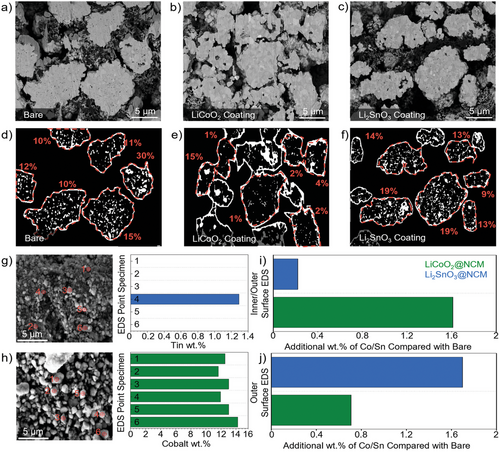
Figure 1g,h shows the SEM imaging of the ball-milled secondary particles coated with Li2SnO3-coated NCM and LiCoO2-coated NCM respectively. The ball milling was conducted to reduce the secondary particles to primary particles and give a general bulk representation of what should be a mix of the internal and external coated particles. As presented in Figure 1i LiCoO2 coated NCM showed a general coverage of Co at ≈1.6 wt.% greater than that of the bare sample across the range of particles examined by Point EDS analysis. Only 1 of the examined points of the Li2SnO3 coated NCM sample returned Sn present at the surface and hence the average coating observed was ≈0.25 wt.%. This data confirms that the internal coating of the Li2SnO3 coated NCM sample is not observed, whilst it is occurring for the LiCoO2 coated NCM sample. To help verify this, EDS mapping of the outer secondary particle surface was conducted for both samples with the data being presented in Figure 1j. The Li2SnO3 coated NCM secondary particle showed a higher level of coverage at ≈1.7 wt.%, in comparison with a much lower ≈0.75 wt.% for the LiCoO2 coated sample. The data of Figure 1i–j when looked at in comparison, draws the conclusion that the LiCoO2 coating is concentrated in the grain boundaries, with the Li2SnO3 coating being concentrated on the outer layer of the particle. Raw data for these experiments are provided in the supplementary Figure S1-S5, Supporting Information. Additional confirmation was confirmed via Point EDS analysis of ion-milled samples coated at a greater wt.% to accentuate the difference between the cobalt values in the pores and in the bulk. This showed a significant increase in the Co values near the surface of the internal primary particles, with a standard value of Co in the center of the internal primary particles for the LiCoO2-coated NCM. Additionally, no Sn was found in the internal primary particles for the Li2SnO3-coated NCM sample. This data has been analysed and represented in Figure S6-S9, Supporting Information.
The structure of the bare- and LCO coated-, and LSO coated-NCM811s was investigated via XRD as seen in Figure S10, Supporting Information. The obtained XRD patterns show characteristic peaks for typical layered structure materials with major peaks such as (003), (101), (006), (102), and (104) at 18.7°, 36.6 °, 38.0°, 38.3°, and 44.5°, respectively. The zoomed-in image in Figure S10a, Supporting Information) shows an identifiable peak at 26.6°, directly corresponding to the characteristic peak of Li2SnO3, the (110) peak [23]. Further characterizable peaks ≈35° and 43°, also attributed to Li2SnO3 (see Figure S10c,d, Supporting Information)).[24] These peaks are presented alongside the XRD data for the bare sample and the LCO-coated NCM811, where no peaks are observed. Additionally, a bright coating over the surface of the NCM811 material can be represented as the LSO coating as provided in the energy dispersive X-ray spectroscopy (EDS) data in Figure S11, Supporting Information. The LCO coating is also expected to be present on the surface of the secondary particle, however, this cannot be determined through XRD nor EDS. Because LCO has an equivalent crystallographic structure and Co is already native to the NCM structure, the LCO coating is not directly distinguishable via XRD or EDS. This can be seen via the EDS data in Figure S12, Supporting Information. To confirm the presence of Li and Co after coating, surface images of NCM811s after sol-gel methods are shown in Figure S13, Supporting Information. It is confirmed that the coating precursors are present on the surface before the 800 °C annealing process for both LiCoO2 and Li2SnO3 coatings.
2.2 Surface Degradation Analysis
The degradation routes were chosen correspondingly to industrially closed conditions which may be unavoidable during the distribution or preparation of active materials by a manufacturer. Additionally, each degradation route helps to isolate the effect of the differing coating protection mechanisms. Such results were reflected in the SEM images, where visual verification of the degradation is possible over the short time that the material was exposed to ambient environmental conditions. The bare NCM811 samples showed surface degradation in all cases with dark patches appearing on the surface of the exposed samples. These dark areas are assumed to be typical surface degrading compounds with lightweight elements such as LiOH and Li2CO3 because more backscattered electrons (BSEs) are emitted from heavier elements such as Ni, Co, or Mn than those from Li during BSE mode FE-SEM.[25] In the case of the bare NCM811, exposure to regular air and elevated moisture air appeared to achieve the highest level of degradation on the particle surface as characterized by the dark substance formations that can be seen in Figure 2b,c. As a recoverability test, the bare NCM811 sample was heated again at 400 °C after the degradation experiments to check if the degradation contaminant compounds could be removed via this method. Exposure to elevated heating appeared to reduce the amount of visually evident surface degradation. The SEM images, as presented in Figure S14, Supporting Information, confirmed that there appear some surface contaminants after heating at such conditions. This suggests that even with a heating step before cell manufacturing, the material may not be able to fully recover its surface properties, once degraded.
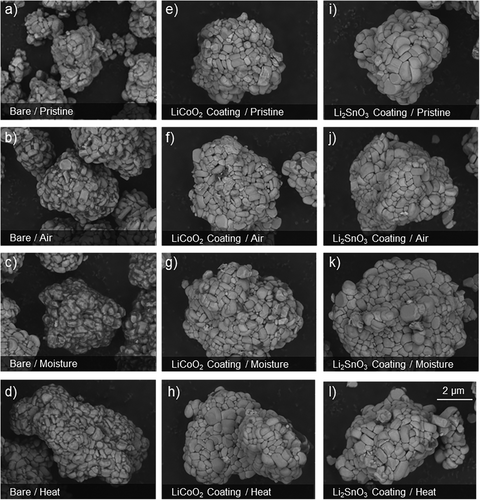
In the case of the surface-coated Li2SnO3, it withstood the surface degradation with significantly less unwanted species appearing on the surface of the samples. This is similar in the case of the LiCoO2 coating, where the outer surfaces morphology of the degraded materials is very similar to that of the original pristine sample. In other words, both the LCO coating and the LSO coating have a prevention effect on the external surface degradation and can form a surface protective barrier which reduces side reactions with the species produced at ambient environmental conditions. This may be attributed to the ability of such coated layered oxide material to utilize some of the problematic surface compounds during its formation from precursor to layered material.[26] It also may remove some of the unstable lithium species at the surface of the NCM material that may otherwise react to form the surface contaminants that are present on the bare sample.[27] Furthermore, forming more structurally stable compounds on the surface of the NCM that maintain lithium-ion conductivity can create a physical barrier between the problematic surface species of NCM811 and the air contaminants, without compromising the electrochemical performance.[28] Additionally, despite the LSO coating samples not showing degradation visually from SEM images, it occurred along the grain boundaries of the primary particles. It is the first indication that the degradation may attack these grain boundary points and potentially cause internal degradation. Protecting these weak points is therefore considered to be an important factor in preventing the degradation of the material. Further SEM data for all samples and degradation routes is provided in Figures S15–S17, Supporting Information. Additionally, Lithium Titration analysis was conducted for the moisture-degraded samples to determine the composition of the lithium residual compounds present after degradation. All results can be seen in Figure S18 compared with the pristine sample, with the degraded coated samples showing a suppression of LiOH formation in comparison to the degraded bare.
2.3 Electrochemical Evaluation of Pristine and Degraded Samples
The electrochemical performances of bare-, LCO coated-, and LSO-coated NCM811 were evaluated to compare their before and after degradation. Before degradation, the coated materials showed highly equivalent performances compared to those of bare NCM811 (discharge capacity of 197.17 mAh g−1 and Coulombic efficiency of 92.9%) as shown in Figure S19, Supporting Information. Figure 3a shows a high-rate cycling data (2 C) for the bare NCM811s before and after degradation. The bare sample performed well maintaining its discharge capacity respectably with the 50th capacity of 185.24 mAhg−1. The electrochemical performance of the degraded NCM811 is consistent with the expectation from the degraded SEM data, with the air and moisture degradation route samples. Significant losses in discharge capacity were observed, with the discharge capacities after 50 cycles being 54.50 mAhg−1 and 18.89 mAhg−1, respectively. Despite showing a level of improvement over the other degraded samples, the elevated heating degradation route sample also performed poorly presumably due to a reasonable level of internal degradation, with the discharge capacity after 50 cycles being 117.20 mAhg−1. This reduction in discharge capacity is observed in the heat-degraded bare NCM811 sample, which is in a good agreement with the literature.[29] The elevated heat preserved the initial charge and discharge capacity, to an extent, however, the capacity fade was considerably worse than the others. This poor cyclability was likely due to the expansion of the pores between the primary particles during heating (Figure S21, Supporting Information), allowing for degradation onsetting molecules such as H2O and CO2 to more easily penetrate and attack the internals of the secondary particle, resulting eventually in reactions with the electrolyte. This is likened to the effects of Ni-rich cathode material expansion and contraction during lithiation and delithiation, often eventually resulting in the cracking of the polycrystalline due to exposure to electrolyte attack.[30] This, alongside the formation of a cathode electrolyte interphase (CEI) layer, could contribute to the large resistance that we see for the bare NCM811 sample in the cycled EIS data in Figure S19, Supporting Information.
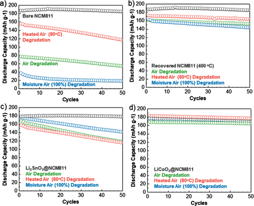
Postdegradation heating of NCM811 bare at 400 °C can recover it from surface degradation (Figure 3b). These samples show a considerable improvement and appear to recover their performance, showing good capacity retentions of 94.96%, 94.10%, and 88.33% for heat, air, and moisture degradation compared to the 98.83% of the pristine. However, they were unable to fully recover their initial discharge capacity, which hence resulted in a substantial decrease in the final discharge capacity over 50 cycles. Interestingly, an identical trend to the degraded bare NCM811s before the postrecovery process was noted with the performance showing the 50th discharge capacities in the order of the bare > heated air > air > moisture air.
In the case of the LSO-coated sample, a different trend was observed in the 50th cycle discharge capacity with the order being pristine > moisture air > air > heated air as shown in Figure 3c. This hints that the LSO coating is primarily defending against the secondary particle surface degradation. The moisture and air exposed samples improved upon the bare NCM811 degraded samples significantly, when considering the 50th cycle discharge capacity, by achieving 141.54 mAhg−1 and 118.69 mAhg−1, respectively. The degraded sample by heated air suffered comparably, achieving a discharge capacity of 115.79 mAhg−1 over the 50 cycles. The trend in this case, pristine > moisture air > air > heated air, suggests that the surface coating was most effective against the degradation which could least easily diffuse internally (i.e., moisture air), and was least affective against the elevated heat degradation route which expands the internal pores allowing for more internal surface degradation to occur. This affirms that the LSO coating, which was relatively effective against the outer surface degradation mechanisms, cannot prevent degradation from penetrating internally into the secondary particle and hence a more applicable coating mechanism is required.
The LCO-coated NCM material showed a considerable improvement over all samples, outperforming the bare NCM811, the recovered NCM811 and the LSO-coated NCM811 (Figure 3d). This is quantified by the maintenance of the discharge capacity after 50 cycles with the pristine, heated air, air, and moisture air samples being 169.29, 177.38 1, 164.61 mAhg−1 and 164.54 mAhg−1, respectively. The maintenance of the initial charge capacity combined with the stability of the sample over cycling resulted in a well-maintained discharge capacity, with all the samples achieving a capacity retention of greater than 96%. Notably, the heated sample increased the discharge capacity in the case of the LCO-coated sample to above its pristine level. This may be as the expanded secondary particle, caused by heating, allows for more contact with the electrolyte. Therefore, in the case of the elevated temperature degradation, the infusive coating of LCO maintains its protection of the internal primary particles despite the increased amount of electrolyte infiltrating the surface. More capacity can be obtained due to more electrolyte contact, without compromising the stability. It also explains the increased levels of degradation for the bare and LSO-coated NCM811 material, where the electrolyte flows in and degrades the surface contaminants already present, likely resulting in gas evolution and cracking. Extended cycle tests were conducted to 100 cycles and have been included in the supplementary data in Figure S20, Supporting Information.
2.4 Internal Degradation Evaluation and Cycle Degradation Evaluation
As previously discussed, the correlation between the visual surface degradation and the electrochemical performance is reasonably clear for the bare NCM811 sample. However, the poorer performance of the LSO coating is comparatively unexplained as both it and the LCO coating showed minimal visual surface degradation. The (003) peak analysis of XRD patterns confirms the trends of the electrochemical data on the degraded samples (Figure 4a–f). The (003) peak shifts to lower angles with the extraction of Li from the cathode structure, which results in various residual lithium compounds.[31] The (003) peak shift shows similar patterns to those of electrochemical cycle performance. Figure 4d shows that the (003) peak of the LCO samples exposed to heated air at a lower angle compared with the bare and LSO samples. This verifies that there is still Li-removal from the slabs at these conditions for LSO-coated NCM811 despite not seeing major external degradation on the surface via the SEM data in Figure 2. Figure 4e shows the same trend with both LSO coated and bare NCM811 shifting to lower angles but (003) peak of only the bare NCM811 shifts after exposure to moisture air. Considering minimal visual degradation in the case of LSO, this Li-removal is likely due to the infusion of H2O and CO2 through the grain boundaries, which can react with the extracted lithium and form degradation compounds. This infusion of the degradation compounds can be likened to that of the liquid electrolyte infusion.[32] It confirms that the reason for poor electrochemical performance was not solely related to the surface contaminants that are visually seen but was likely also related to the removal of Li from the Li slabs due to degradation in the more penetrative atmospheric degradation conditions.
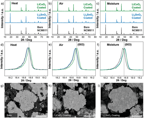
To further support our hypothesis, the cycled electrodes for the degraded samples at heated air were ion-milled with the SEM data (Figure 4g–i). Bare- and LSO-coated NCM811 show clear intergranular cracking along the grain boundaries. The generated cracking could be associated with oxygen evolution, which can be exacerbated by surface degradation impurities that can oxidize the electrolyte during cycling. [33, 34] These cracks tend to propagate along the intergranular pores, of which the LSO coated and the bare NMC811 sample possess significantly, and which the percentage of such was increased by exposing them to heated air (Figure S21, Supporting Information). More images showing cracking are provided in Figure S22. Hence, it can further be determined that the improved performance of the LCO coating is directly related to the ability of the coating to infuse and reduce such intergranular pores. This is particularly vital for explaining the improved ability to withstand to heated air exposure that can expand the secondary particles and allow internal surface degradation to occur alongside increased levels of oxygen evolution.[35] The LSO coating exposed to heated air exhibits the greatest sample porosity and that shows a poor performance. Additionally, the lack of intergranular pores in the LCO-coated NCM811 may reduce the amount of electrolyte able to enter and hence reduce the degradation associated with electrolyte contact on NCM material.
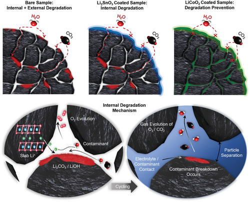
The confirmation of the release of Li from the lithium slabs via XRD (003) peak analysis, combined with the electrochemical data and cycled electrode NCM cracking data determines that the prevention of the formation of outer surface degradation compounds is not enough to prevent ambient environment degradation and that a suitable coating requires the ability to prevent the diffusion of damaging compounds through protecting the grain boundaries. This is detailed in Figure 5, with the coating mechanisms and their respective impacts on the internal and external degradation being displayed alongside the corresponding attack mechanisms of the internal degradation. The elucidation of lithium from the Li slabs, and the reaction of this lithium with environmental contaminants to trigger oxygen evolution reactions has been further highlighted. This eventually results in cracking after the introduction of electrolyte and electrochemical cycling and can be considered a key contributor to the capacity fading reported in the results.
3 Conclusion
In this study, we investigated the electrochemical performance of bare-, LiCoO2 coated- and Li2SnO3 coated- NCM811 after undergoing accelerated degradation via exposure to the atmospheric conditions of standard air, air at elevated temperature, and air with elevated moisture content. The formation of external degradation compounds on the NCM surface was prevented by the outer particle coating of Li2SnO3; however, the electrochemical performance could not be well maintained compared to the pristine sample, with the elevated heat performance resulting in an initial discharge capacity as low as 115.79 mAhg−1. This was attributed to its inability to prevent structural and internal degradation caused by the infusion of ambient environment compounds. The applied degradation routes resulted in more significant internal separation and cracking of the particles after cycling in both the internally unprotected particles of the Li2SnO3 coated sample and the bare NCM811. Conversely, the LiCoO2 coating was very effective against all forms of degradation, due to its ability to protect the internal primary particles from infusive degradation via coating of the intergranular pores. This results in a significantly improved electrochemical performance for the LiCoO2-coated NCM811 over the other samples for all the degradation routes, with the capacity retention for all the degraded samples being greater than 96% over 50 cycles at 2 C. This is attributed to the ability of the LiCoO2 coating to 1) prevent formation of external degradation compounds and 2) suppress the formation of internal degradation including particle separation and removal of Li from the Li slabs. Our research highlights the importance of the chosen surface modification mechanism, with a particular consideration of coating morphology, to protect against degradation in polycrystalline particles. Our findings elucidate that surface modification with the correct selective coating mechanism can ensure that the electrochemical properties of the NCM811 can be maintained over short-term exposure to a variety of ambient environmental conditions. Applying this pro-active surface modification approach will reduce the reliance on unsatisfactory post-production processes to recover exposed Ni-rich active material and assure the integrity of the active material during cell manufacturing.
4 Experimental Section
Surface Modification Method
Pristine NCM811 was obtained from POSCO Chemical for surface modification, with Li(CH3COO)·2H2O, Co(CH3COO)·4H2O and Sn(CH3CO2)2 (Sigma–Aldrich). A typical sol-gel surface modification method was applied to the coating process. The acetate precursors (Li+Co/Li+Sn) of suitable weight for 1 wt.% coating were fully dissolved in anhydrous ethanol solvent (28 g) at 200 rpm until fully dissolved. 4 g of the preprepared NCM811 sample was added, and the heat was increased to 120 °C. The samples remained at the mentioned conditions until the solvent had fully evaporated. The samples were then dried at 150 °C for 2 h, before being annealed at the most suitable condition predetermined for each individual precursor to coat in the required way. LiCoO2 samples were annealed at 800 °C in an air atmosphere for 4 h, while Li2SnO3 samples were annealed at 800 °C in a pure O2 atmosphere for 4 h. These methods applied in this study to achieve grain-infused boundary coatings were adapted from the J. Cho group.[22]
Degradation Method
Time-degraded samples were left exposed to standard air conditions of the lab environment which were consistently ∼50% humidity and 25 °C. The top of the sample was covered with perforated aluminum foil to reduce contamination. The samples were left for 24 h. Moisture-degraded samples had their environment moisture levels maintained at ≈100% for 24 h. The 100% level was maintained by keeping the sample in a closed system above pure water. The samples were in a closed system so did not require perforated aluminum foil The samples were left for 24 h. Heat-degraded samples were heated at 80 °C for 24 h. The samples were not in a closed system, and therefore had perforated aluminum foil coverings to reduce contamination. The samples were heated in a standard drying oven.
Electrochemical Characterization Method
The cathode electrode composite was comprised of the active material (NCM811), poly(vinylidenefluoride) (PVDF) binder, and Super P as the conductive material in a ratio of 92:4:4. The cathode electrode was then produced via casting onto aluminum foil with a manual doctor blade with the active material loading at ≈6–7 mg cm−2. The electrolyte used was 1 M LiPF6 in ethylene carbonate (EC) / dimethyl carbonate (DMC) (1: 1 vol. %). The electrochemical data was attained via half-cell coin cell testing (2032R). The conditions applied for the formation cycle were 0.1 C and voltage range 3.0–4.3 V, with the C rate being increased to 2 C for the cycling of the cells and the voltage range remaining the same. The temperature of all formation and cycling tests was 30 °C.
Ball-Milling Method for Internal/External Coating EDS Analysis
The samples were taken with their respective coatings and ball milled with zirconia balls of 5 mm at 1500 rpm for 20 minutes, until almost complete destruction of the secondary particles was achieved. The samples were then used in EDS Point analysis and EDS mapping analysis to determine the composition of a mix of internal and external primary particles.
Characterization Method
Powder X-ray diffraction (XRD) data was analyzed via D/Max2000, Rigaku. The measurements were taken between 2θ = 10–80o with radiation from source Cu Kα radiation. SEM TESCAN (VEGA II LSU) was used to identify the sample morphology and degradation occurring on the surface and internally in back-scattered electron (BSE) mode. For EDS HORIBA was used. The cross-section SEM images were attained via firstly ion-milling the samples with Gatan (697 Ilion II) system. Image processing was conducted using Image-J.
Acknowledgements
This research was supported by the Basic Research Program through the National Research Foundation of Korea (NRF) funded by the MSIT (2020R1A4A1019463) and was supported by the Korea Institute of Energy Technology Evaluation and Planning (KETEP) grant funded by the Korean government(MOTIE) (20221B1010003B, Integrated High-Quality Technology Development of Remanufacturing Spent Cathode for Low Carbon Resource Recirculation).
Conflict of Interest
The authors declare no conflict of interest.
Author Contributions
T.J.E. and J.Y. contributed equally to this work. Conceptualization, T.E., J.Y., J.C., P.O.; methodology, T.E., Y.S., J.C., J.Y.; validation, P.O., J.C., J.Y.; formal analysis, T.E., J.Y., J.C., C.L.; investigation, T.E., J.Y., J.C.; resources data curation, T.E., J.Y.; writing—original draft preparation, T.E., J.Y., J.H.; writing—review and editing, T.E., J.Y., J.H., C.L.; visualization, P.O., Y.S.; supervision, P.O., Y.S.; project administration, P.O., Y.S.; funding acquisition, P.O., Y.S.; All authors have read and agreed to the published version of the manuscript.
Open Research
Data Availability Statement
The data that support the findings of this study are available in the supplementary material of this article.


