Optically transparent nanocomposite films based on poly(vinylidene fluoride) and single walled carbon nanotube: Role of process parameters on polymorphic changes
Abstract
Cloudy films with uneven texture are commonly observed during the fabrication of poly(vinylidene fluoride) [PVDF] films which prevent the usage of the films for optical applications. This article highlights fabrication of optically transparent and electroactive PVDF films and their nanocomposites using functionalized single walled carbon nanotube (FSWCNT) through a novel yet simple processing technique of ultrasonication coupled with vacuum drying. The morphology, optical transparency, electrical, and mechanical properties of the films are reported here. Our previous work demonstrated that functionalization for 4 hours was the optimum time for the maximum incorporation of functional groups into the SWCNT surface. When such optimally functionalized SWCNTs are incorporated in PVDF through the process of ultrasonication followed by vacuum drying, smooth and transparent films with predominantly γ-phase have been obtained. Such films display superior electrical and mechanical properties compared to their neat counterparts. Finally, a comparison between air-drying and vacuum drying processes in presence of ultrasonication shows that former gives cloudy films with predominantly γ phase while the latter produces smooth and optically transparent electroactive film.
1 INTRODUCTION
Poly(vinylidene fluoride) [PVDF] with high electroactive properties like piezo, pyro, and ferroelectricity and good dielectric response are being used in a variety of applications such as sensors, actuators, energy harvesting devices, and hydrophobic coatings.1-3 In order for the polymer to utilize its full capabilities, the processing technique needs to be modified appropriately.4 Fabrication of PVDF films with thickness up to 500 μm is carried out by using a doctor blade. However, for the production of thin films with thickness varying from few nanometres to tens of micrometers, spin coating is the best protocol. The advantage of using doctor blade is that PVDF film and its nanocomposite are produced on rigid or flexible surfaces with minimum wastage, forming flexible, flat, dense, and highly polarizable films.5 Optically transparent polymer film of Poly(vinylidene fluoride-co-trifluoroethylene) [P (VDF-TrFE)], a copolymer of PVDF, is reported to be fabricated by spin coating followed by thermal annealing at 70°C.6
Films with diverse patterns, which are required for the designing of new printable smart materials like biomedical and environmental sensors, large area displays, and circuits' are fabricated using different printing procedures like ink-jet, screen and spray printing. Designing of porous polymer structures finds wide acceptance in industrial applications and scientific research because of their excellent thermal and hydrolytic stability, high chemical resistance, and mechanical properties. Porous PVDF structures are produced by following several protocols like vapor induced phase separation (VIPS), temperature induced phase separation (TIPS), solvent casting technique, freeze extraction, and replica molding. Such PVDF structures find applications in lithium-ion battery separators, tissue engineering, gas separation, filtration membranes, pollutant deduction devices, and water treatment.7-10 VIPS follows a well-documented mechanism where the PVDF films are cast by using a high boiling point solvent such as N, N- Dimethylacetamide (DMAc) which evaporates slowly. Through the process of diffusion, water vapor present in humid air penetrates into the film as it is miscible with DMAc. Since the boiling point of DMAc is relatively high, it has a slow evaporation rate compared to the water intake. The process then results in phase separation, as water is insoluble in PVDF resulting in the formation of an open porous microstructure of PVDF.11 The final properties of the porous films depend on the polymer concentration, solvent, and nonsolvent type and their exchange rate.
Fibrous and spherical PVDF structures are formed by electrospinning and electrospraying techniques depending on the solution concentration.12, 13 It is to be noted that the polymer solution concentration plays an important role in the formation of fibrous and spherical morphologies. Spherical morphology is preferred when the PVDF concentration is between 5 and 10 wt%, that is, for diluted and semi-diluted concentrations while fibrous morphologies are preferred for concentrated solution of PVDF (content of PVDF between 20 and 30 wt %).14 All the above protocols produce films with excellent crystallization into polar phase having high uniformity with remarkable properties like high mechanical and electrical properties, elevated chemical stability and dielectric strength, thus finding applications as ultrasonic transducers, sensors and actuators, ferroelectric and energy harvesting devices.15, 16
PVDF is crystallized into polar γ phase through various methods such as isothermal crystallization at 170°C for about 20 hours with slow cooling rates, by thermally induced phase transformation from α phase at temperature >160°C17 and by solution casting technique with ultrasonication for 60 minutes and solvent temperature below 100°C.18 However, there are also some issues to be addressed during the crystallization of PVDF films into γ phase. It is to be noted that during isothermal crystallization, the growth rate of γ phase crystals at higher temperature is slower in comparison to the α phase. Also, in solution casting technique when the time of ultrasonication exceeds to 120 minutes, there will be a phase inversion from γ phase to α phase.18 Thus, proper control of processing technique is important for the maximum crystallization into polar γ phase in PVDF films. Addition of suitable fillers like clay,19 zeolite, and KBr20 in PVDF also result in crystallization into γ phase. The filler-polymer interaction leading to the nucleation of electroactive phases in PVDF is not universal. It depends on several factors such as surface charge, size, interactions at the interface between the local electric field around the nanoparticles and the PVDF dipoles and the processing technique. It is found that the electroactive phase of PVDF increases with the addition of ferrite nanoparticles possessing higher negative electrostatic charge. The crystallization mechanism in such nanocomposites prepared by melt processing is attributed to an enhanced interaction between the negatively charged filler particles and the CH2 groups in PVDF.21 In a study by Mendes et al.,22 the crystallization of PVDF nanocomposites prepared by using the ceramic filler BaTiO3 is strongly depended on the size of the filler particles. Similar mechanisms are also reported for palladium doped PVDF films and gold nanoparticles doped PVDF films.23, 24 The crystallization of PVDF films in presence of carbon nanotubes is achieved by the process of ultrasonication which provides the required energy for the transformation from the nonpolar to polar phase.
It is reported that PVDF nanocomposites based on different clay structures processed by solvent casting and melt crystallization produce optically transparent films.19 Optically clear smooth PVDF films find relevant applications in microelectronics such as ferroelectric memories for data storage, low voltage operation, as transparent films in the optical path of a detection system.6 Normal fabrication procedures like solution casting result in cloudy and rough PVDF films with poor electrical characteristics.25-27 Fitrilawati et al.28 produced optically clear thin PVDF films by spin under nitrogen atmosphere and higher substrate temperature. Li et al.29 also fabricated smooth and optically clear PVDF films by the technique of wire bar coating from DMF solution, producing 1 μm layer thickness at relatively low humidity. Transparent and smooth films are also processed by the addition of nanofillers like nanotubes into the polymer matrix as transparency is one of the important physical properties achieved when nanofillers are used. Transparency is achieved in nanocomposites as the size of the nanofiller becomes smaller than the wavelength of visible light thus contributing less to scattering of light. However, only when there is an efficient dispersion of nanofillers in the polymer matrix, transparency occurs. Optically transparent and smooth polymer composites based on PVDF has been reported by the incorporation of metal and inorganic nanoparticles like CaF2, Zeolites, organically modified silicate, and so on.30-32 However, to the best of our knowledge, studies aiming at achieving optical transparency with high mechanical and electrical properties in PVDF films with the introduction of one dimensional nanotube are scarce.
In the present study, we report a relatively less energy consuming technique of short duration ultrasonication followed by vacuum drying for the preparation of smooth and optically transparent PVDF films and its nanocomposites, which crystallize in the polar γ phase. All the aforementioned fabrication techniques mainly focus on the processing of virgin PVDF films but we report the incorporation of FSWCNT fillers and their role in producing optical transparency and nucleation to polar γ phase in PVDF. Functionalized nanotubes are chosen here since pristine nanotubes result in the formation of agglomerates in PVDF matrix, thus preventing the formation of transparent films. The films thus processed show excellent transparency along with good electrical and mechanical properties.
2 EXPERIMENTAL
2.1 Materials
Single walled carbon nanotubes (SWCNTs) used in the study was procured from M/s Southwest Nano Technologies, Norman, Oklahoma. Their diameters are in the range of 0.7 to 1 nm and length varies between 2 and 5 μm. Functionalization of SWCNT was done using conc. HNO3 (69% w/w) which was obtained from Merck, India. PVDF was procured from M/s Alfa Aesar, UK with CAS No. of 24937-79-9 and product No. of 44080. The solvent used was N-dimethyl acetamide (DMAc, 99.5%) which was obtained from M/s Finar, India.
2.2 Functionalization of SWCNTs
SWCNTs have been functionalized using conc. HNO3 by the procedure already reported by us.33 Here, the optimum duration of functionalization of SWCNTs has been arrived at through a combination of spectroscopic, thermal, and morphological analyses (ESI). Based on the studies, it was found that 4 hours is the optimum duration of functionalization of SWCNTs chosen by us as it has the maximum composition of different functional groups viz. carboxyl (–COOH), hydroxyl (–OH), and carbonyl (C=O) functionalities along with least defects. The optimization of functionalization of SWCNT is experimentally validated in fluorosilicone and vinyl terminated polydimethyl siloxane polymers where the viscoelastic, adhesive, and acid resistant characteristics were maximum for the 4 hours functionalized SWCNT incorporated fluorosilicone polymer.34, 35 Hence, for the present study as well, we chose SWCNT functionalized for 4 hours for the preparation of PVDF based nanocomposites and is denoted as FSWCNT-4 in the rest of the article.
2.3 Preparation of PVDF films and nanocomposites through vacuum drying
Solution casting method was adopted for the preparation of PVDF films. In a typical experiment, 2 g PVDF powder was dissolved in 20 mL DMAc followed by continuous stirring at 60°C for the complete dissolution of PVDF in DMAc. Further, the mixture solution was ultrasonicated by using a Hielscher UIP1000hd industrial ultrasonic processor operating at 1000 W power, 20 kHz frequency and 25 μm amplitude, using BS2d18 sonotrode for 5 minutes. PVDF films were fabricated by pouring the ultrasonicated solution on to a glass plate followed by casting using a doctor's blade. The thickness of the prepared film was 0.40 ± 2 μm. The cast films were vacuum dried at 70°C for 2 hours. For a comparison of the processing parameter (to study the effect of ultrasonication), film without ultrasonication was also prepared. In order to study the mechanism of formation the films, one film was prepared by following the same procedure where instead of vacuum drying, air drying at 70°C for 2 hours was performed.
In the preparation of PVDF nanocomposites, initially the modified filler (FSWCNT-4) was dispersed in 20 mL DMAc by ultrasonication for 15 minutes to get a stable colloidal dispersion. Further, 2 g of PVDF powder was added into the dispersion followed by stirring at 60°C so as to completely dissolve PVDF in DMAc. For the complete blending of PVDF in FSWCNT-4, ultrasonication was carried out for 5 minutes followed by casting of composite films. Different composite films were prepared by using 0.01, 0.05, and 0.1% FSWCNT-4 in the polymer. Here also, for a comparison, a nanocomposite film without ultrasonication was also prepared and cast by the same procedure as above. For studying the mechanism of formation of nanocomposite films, one nanocomposite film was prepared by following the air-drying route instead of vacuum drying.
2.4 Characterization
Perkin Elmer Spectrum GX FTIR spectrophotometer in ATR mode was used for the determination of phase changes in the films in the region of 4000 to 550 cm−1 at a spectral resolution of 2 cm−1. Bruker D8 Discover diffractometer was used to determine the XRD profile of the samples whose 2θ ranges between 10 and 30°. A WITec alpha 300R Confocal Raman microscope with a 532 nm laser source was used for the Raman spectral studies of the films. The instrument is equipped with a ×50 air objective and 600 grooves/mm grating. In order to obtain a single spectrum, five spectra were accumulated for an integration time of 1 second. The percentage transmittance of the films was done using Perkin Elmer Lambda UV-Vis-NIR spectrophotometer. The crystallization pattern of the film was taken using TA Instruments' differential scanning calorimetry (DSC) model Q20 at the heating/cooling rates of 5°C/min. Morphological analysis of the films were done using a Nova Nano SEM 450 field emission scanning electron microscope (FESEM) at two different accelerating voltages viz. 5 and 20 kV. Gold sputtered films were used for the FESEM analysis and the sputtering was done using a Leica sputter coating machine EMSCD005 by the technique of plasma vapor deposition. Morphological analysis using atomic force microscopy (AFM) was carried out using Agilent 5500 scanning probe microscope in contact mode. INSTRON 5569 Universal Testing Machine (UTM) was used to determine the tensile strength and modulus of the films. The testing was done as per ASTM-D 882 by analyzing atleast five samples of each type with a crosshead speed of 50 mm/min and a gauge length of 80 mm. TEGAM 3550 LCR meter was used for determining the capacitance of films. The measurements were done at a temperature of 23°C ± 2°C and relative humidity of 60% ± 5% at 1 kHz frequency and applied voltage of 500 V as per ASTM D-257 method.
3 RESULTS AND DISCUSSIONS
3.1 Effect of ultrasonication and vacuum drying on the phase changes and properties of unfilled PVDF films
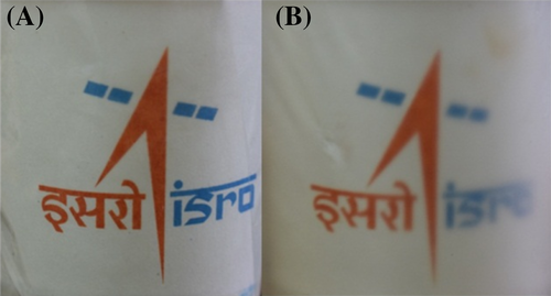
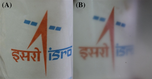
To study the effect of ultrasonication on the properties of vacuum dried PVDF films, the neat polymer is subjected to ultrasonication and is denoted as P-US-VD. A film without ultrasonication is also prepared by vacuum drying process for comparison, which is denoted as P-VD. Figure 1 shows the photographs of P-US-VD (left) and P-VD (right). It is evident that ultrasonication of the polymer prior to vacuum drying produces optically transparent PVDF films inferring the influence of processing conditions in determining the morphology and microstructure of PVDF films. In order to understand the reasons for the change in optical transparency, detailed morphological analysis of the films have been carried out.
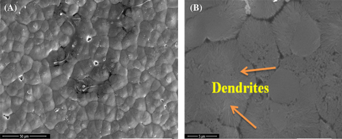
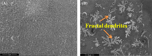
Morphology of the films processed without and with ultrasonication shows fused spherulites with much less porosity as observed in the FESEM images of P-VD.36 Figure 2A shows the surface morphology of P-VD in low magnification where the spherulites are clearly visible. The diameter of the spherulites is measured to be greater than 5 μm. At higher magnification (Figure 2B), it is observed that at some points, the spherulites are transformed into dendrites. Remskar et al37 prepared nanocomposites based on PVDF and molybdenum disulfide where the films crystallized through annealing at 110°C produced dendritic morphology along with the spherulites. On the other hand, the morphology of P-US-VD indicates that the spherulite structure is suppressed as shown in Figure 3. Here the spheres get more and more connected forming a dense smooth film without any pinholes as shown in Figure 3A. Hence, ultrasonication of PVDF results in both physical and chemical changes of the polymer. The process of ultrasonication produces a temperature of about 5000 K, a local pressure of 50.6 MPa as well as a much higher heating and cooling rates which is greater than 109 K/s.24-38 As a result, the chains of PVDF are exposed to severe forces which cause fast flow of liquid near the collapsing cavities along with shock waves which are produced after the implosion of bubbles. This high energy aids in fusing of the spherulitic morphology in a uniform fashion making the film transparent. This processing condition also results in a fractal dendritic pattern of crystallization as shown in Figure 3B. Li et al.25-29 reported similar observations in PVDF films prepared at low relative humidity of 0% and high substrate temperature of 120°C.
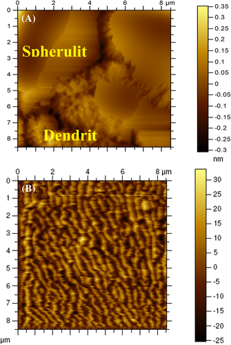
To further evaluate the morphology of the films, AFM analysis was done and the images are given in Figure 4. Here also, P-VD exhibits spherulitic morphology similar to those observed in FESEM images, with characteristic dendritic phase (Figure 4A). On the other hand, P-US-VD reveals a lamellar nanostructure of the fractal dendrite on the surface of dense compact morphology as shown in Figure 4B. In addition, the crystal size in P-US-VD is much smaller than P-VD. That is, the energy induced during ultrasonication causes nucleation and mocro crystallites are formed.
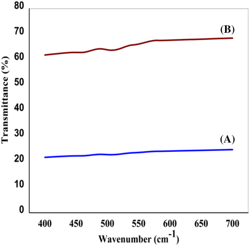
The optical transparency of the films is measured using UV-Vis-NIR spectrophotometer and the spectra are given in Figure 5. Transmittance of P-US-VD in visible region is greater than 60% in comparison to P-VD where transmittance is only in the range of 20% to 25%. This is attributed to the proper orientation of the polymer chains as a result of ultrasonication along with controlled evaporation of solvent under vacuum conditions leading to the formation of dense smooth films as observed from FESEM analysis. To confirm the proper stacking of polymer chains leading to optical clarity in PVDF films, we need to look into an example from nature, which is the Cornea, serving as the front cover of eye. The morphological features of Cornea have well defined lamellar sheets with aligned fibrils surrounded by an optically homogeneous ground substance. These fibrils are long with thickness in the nano-regime producing good clarity to the Cornea.
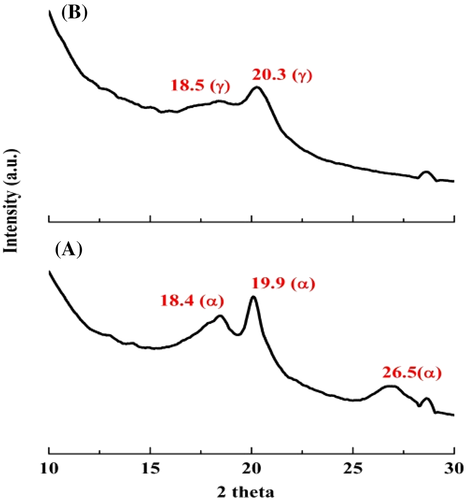
The predominant crystalline phase of the films has been further confirmed by XRD, FTIR, and Raman spectroscopic studies. Figure 6 shows the XRD patterns of P-VD and P-US-VD. It is evident that for P-VD (Figure 6A), the crystalline peaks corresponding to the nonpolar α phase of PVDF predominates at 18.4, 19.9, and 26.5° which are attributed to (020), (110), and (021) crystal planes respectively. However, for P-US-VD (Figure 6B), new peak corresponding to the polar γ phase at 2θ value of 20.3° is present.26-39 This peak is assigned to the overlapping of (101) diffraction patterns.
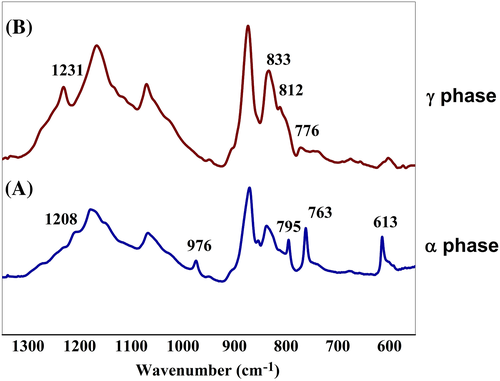
Results of FTIR studies, given in Figure 7, corroborate the findings of X-ray diffraction studies. For P-VD, the absorption bands that correspond to α phase viz. 613, 763 (CF2 bending and skeletal bending, respectively), 795 (CH2 rocking), 976 (CH2 twisting), and 1208 cm−1 (CF2 asymmetric stretching mode and CH2 wagging) are evident in the spectrum confirming the formation of nonpolar α phase.27-40 However, for P-US-VD, strong absorption peaks which are characteristics of γ phase emerge at 812 cm−1 (CH2 rocking), 833 cm−1 (CF2 symmetrical stretching, and C–C asymmetrical stretching), and 1234 cm−1 (CF2 asymmetrical stretching and rocking) with almost complete disappearance of α phase peaks.28-42 This change from nonpolar α phase to polar γ phase is achieved just by introducing ultrasonication followed by subjecting the films to vacuum drying.
 (1)
(1)| Sample | Percentage of γ phase, F γ (%) |
|---|---|
| P-VD | 30 |
| P-US-VD | 97 |
In the equation, Aα and Aγ denotes the absorbance at 763 and 833 cm−1, respectively, while Kα and Kγ are the absorption coefficients at respective wave numbers whose values are 0.365 and 0.150 μm−1, respectively.31-44 It is found that P-US-VD contains 97% γ phase compared to P-VD which is having only 30% γ phase. Hence, the process of ultrasonication followed by vacuum drying results in the conversion of almost all α phase into γ phase.
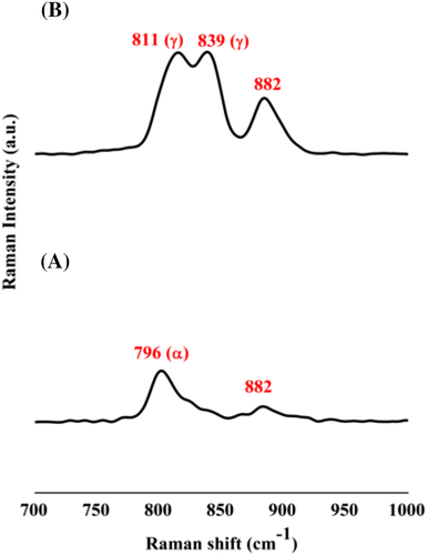
To further compliment the results obtained from FTIR and XRD analyses, Raman spectroscopic studies have been carried out. Raman spectra in Figure 8 show that changes are happening in the PVDF films when they are subjected to different process conditions. A typical Raman spectrum of a PVDF film shows four major peaks. The first peak observed around 796 cm−1 denotes the presence of α phase. The second and third peaks at 811 and 839 cm−1 respectively correspond to the polar γ phase. The fourth peak at 882 cm−1 is a combination peak of all the three phases of PVDF.32-45 The Raman spectrum of P-VD (Figure 8) shows only a single major peak at 796 cm−1 which corresponds to the nonpolar phase. However, P-US-VD shows two peaks at 811 and 839 cm−1 corresponding to the polar phase. This further confirms that the simple process of ultrasonication followed by vacuum drying could transform PVDF into its electroactive phase.
 (2)
(2)| Sl.no. | Film | TC (°C) | ΔHC (J/g) | XC (%) |
|---|---|---|---|---|
| 1 | P-VD | 135.53 | 39.4 | 37.7 |
| 2 | P-US-VD | 136.37 | 43.5 | 41.6 |
- Abbreviations: ΔHC, enthalpy of crystallization; TC, crystallization temperature; XC, percentage.
It is evident that the percentage crystallinity is controlled by the change in processing conditions adopted for the preparation of PVDF films. Films prepared through ultrasonication followed by vacuum drying are more crystalline in comparison to the film prepared without ultrasonication. Consequently, an increase in the enthalpy of crystallization, (ΔHc) is also observed for the former. This confirms that the controlled processing of ultrasonication assisted vacuum drying aids in crystallization of PVDF films with phase transition from α phase to the polar γ phase. The crystallization temperature (TC) is also shifted to higher values for P-US-VD.
The change in polymorphism results in change in the electrical properties of the films where the polar γ phase is the major contributing factor.34-47 With increase in the γ phase content in the matrix, there is an improvement in the electrical properties. Table 3 shows that the capacitance of P-VD, having a γ phase fraction of 30 is 249.8 pF. However, upon inducing ultrasonication assisted vacuum drying (P-US-VD), the capacitance increases by 75% (436.2 pF). Thus, a simple process of ultrasonication assisted vacuum drying inducing polar γ phase in PVDF increases the electrical properties. This observation validates the findings made through spectroscopic and morphological analyses.
| Sample | F(γ)% | Capacitance (pF) | Modulus (MPa) | Tensile strength (MPa) | Elongation at break (%) |
|---|---|---|---|---|---|
| P-VD | 30 | 249.8 ± 4.5 | 1146 ± 6 | 29 ± 0.9 | 4.0 ± 0.05 |
| P-US-VD | 97 | 436.2 ± 5.2 | 1469 ± 7 | 34 ± 0.7 | 3.7 ± 0.07 |
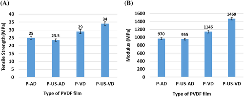
Change in process conditions causes significant changes in the mechanical properties of the films as observed in Table 3. The film prepared through ultrasonication assisted vacuum drying (P-US-VD) shows higher modulus and tensile strength compared to the one prepared by vacuum drying alone (P-VD). As already described, the process of ultrasonication imparts high energy density in the solution producing a very high temperature and pressure which cause the α polymer chains to easily overcome the energy barrier between TGTG and TTTG configurations and thus transforming into γ phase. This phase change is confirmed from the microstructure of the polymer films where P-VD show fused spherulites characteristics of α polymorphic structure while P-US-VD with a dense and smooth compact morphology show γ polymorphic phase (Figures 2 and 3, respectively). The change in morphology as a result of change in processing conditions influences the mechanical performance of the films. Another factor, which affects the mechanical properties of the films is the type of drying adopted during the preparation of the films. In the present investigation, the films were prepared by vacuum drying. Another common method of film preparation is drying the cast films in ambient conditions in air atmosphere. To compare the effect of drying conditions, two more films were prepared, one with air drying alone (where the solution is not subjected to ultrasonication) denoted as P-AD and the other with air drying where the solution is subjected to ultrasonication prior to air drying which is denoted as P-US-AD. The FTIR, XRD, Raman spectroscopic, and FESEM analysis of these films are given in Supporting Information. Both the films, which are subjected to air-drying (irrespective of subjecting the solution to ultrasonication prior to air drying) crystallized in α phase. The mechanical properties of these films are compared with those of P-VD and P-US-VD (which are subjected to vacuum drying) and are given in Figure 9. On comparing the tensile strength of all the PVDF films, it is observed that the films, which are subjected to air-drying have lower tensile strength and modulus compared to those subjected to vacuum drying irrespective of the solutions being subjected to ultrasonication prior to the drying process. The tensile strength and modulus of P-VD show an increase of 16% and 18%, respectively in comparison to P-AD while those of P-US-VD show an enhancement of 45% and 54%, respectively in comparison to P-US-AD.
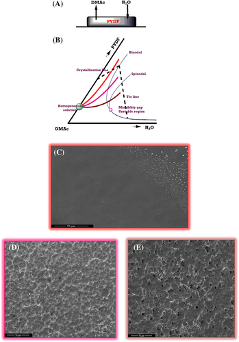
On comparing the microstructure of PVDF films prepared through vacuum drying (P-VD) and air drying (P-AD) (Figures 10D,E, respectively) the air dried film has a microstructure consisting of a structure where bulbous particles are connected together through cords arising due to the number of pores present, which causes a decrease in the mechanical properties than P-VD which shows fused spherulites, even though both crystallizes in nonpolar α phase. Further, on observing P-US-AD (Supporting Information), it shows a porous spherulitic morphology, characteristics of α polymorphic structure whereas P-US-VD (Figure 10C) show a dense and smooth compact morphology of γ polymorphic phase. Thus, the drying conditions have a direct role in controlling the microstructure of PVDF films, which influences their mechanical performance.
This comparison in properties demonstrates that to prepare PVDF films with multifunctional properties including high optical transparency coupled with excellent electrical and mechanical properties, ultrasonication followed by vacuum drying is the most favorable approach. The process of ultrasonication provides the necessary energy for the conversion from nonpolar α phase to polar γ phase in PVDF films while vacuum drying provides controlled evaporation of the solvent producing dense microstructure as seen from FESEM images. The salient feature here is that all these properties are achieved without the addition of any external agents.
The mechanism of formation of different phases of PVDF films through ultrasonication and vacuum drying is explained using VIPS, which is well documented for PVDF membranes.7-11, 48 The formation of membranes occurs as a system comprising of three components- that is, a combination of polymer, solvent, and nonsolvent where the solvent and nonsolvent are fully miscible here for the PVDF polymer. Typical solvents are high boiling point solvents like NMP, DMSO, DMF, or DMAc. Here the membranes are formed when the nonsolvent, that is, water, is diffused to the matrix, resulting in phase separation. Thus, a ternary phase diagram is formed in the case of PVDF membranes. A similar kind of phase separation occurs in the PVDF films prepared in the present study.
The schematic of the role of solvent and nonsolvent in deciding the morphology of PVDF films is shown in Figure 10. Here, PVDF films are cast using DMAc, which has slow evaporation rate due to its relatively high boiling point. Humidified air contains water vapor that is fully miscible with DMAc, which enters into the film through diffusion (Figure 10A). Here, the absorption of water occurs at a faster rate than the evaporation of DMAc. For PVDF, water is a nonsolvent; therefore, phase separation occurs. The ternary phase diagram of PVDF under the present study is given in Figure 10B. The pink dot here denotes critical point. In the beginning, the mixture is a homogenous solution denoted by the greet dot. Upon drying, PVDF film takes three different possible routes for the formation of the composition, which are represented by the brown, pink, and orange lines.
To explain the morphology of PVDF films in the present study, the multifaceted relationship of phase separation between equilibrium thermodynamics as well as mass transfer kinetics by Matsuyama et al. are looked upon.7-11, 48 They derived an isothermal phase diagram involving the three components, that is, PVDF, DMF, and H2O. Their work comprises of calculating the binodal and spinodal lines from the Flory-Huggins parameters. Here, from the depression of melting point, the isothermal crystallization line is obtained and the mass transfer is calculated by solving the one dimensional diffusion equations. Matsuyama et al.,11, 48 verified the calculations to prepare 256 μm thick PVDF films at room temperature under restricted humidity. Morphology of the membranes were analyzed by microscopy and it was compared with composition path calculated using the phase diagram. Both were found to be in good agreement. Thus by using the phase diagram, morphology of the PVDF films is deduced. The FESEM images for the PVDF films prepared by Matsuyuma et al.11, 48 showed three different types of morphology for PVDF under different experimental conditions. When the relative humidity is low, the films are having a close packed microstructure. Here the bimodal is not crossed by the system. The wet film is stable without any liquid-liquid phase separation. As the relative humidity is increased, nucleation of the globules occurs and they grow and coarsen eventually. Here the bimodal is crossed by the film when they are dried, but the spinodal is not crossed. Thus the composition here is in the metastable region occurring between the bimodal and spinodal, above the critical point. Liqud-liqud demixing is occurred here. As the relative humidity is increased further, a thread-like structure of spherical spherulites are formed which are connected loosely. Here, spinodal is crossed by the composition, entering into the unstable region. The composition crosses the spinodal and enters the unstable region. The formation of the microstructure is explained in this way using the phase diagram with the help of compositional trajectories.
In the above discussion on phase separation, PVDF films have been prepared by three independent techniques, that is, air-drying (P-AD), vacuum drying (P-VD), and ultrasonication followed by vacuum drying (P-US-VD). The FESEM images of PVDF films processed under these conditions is shown in Figure 10C-E. The film prepared using ultrasonication followed by vacuum drying (P-US-VD) denoted by the orange outline (Figure 10C), represents a condition of high substrate temperature provided by ultrasonication and a low humidity as a result of vacuum drying. In such conditions, there is no absorption of water in the film resulting in no phase separation thus forming smooth intense films. The binodal of the phase diagram is not crossed by such compositions. However, the film prepared through vacuum drying alone (P-VD) as shown by pink outline in Figure 10D, represents a condition of low relative humidity and an intermediate temperature. Here, the globules undergo nucleation thereby causing their growth and finally they coarsen. Such a composition occurs in the metastable region, that is, between the bimodal and spinodal. Liquid-liquid demixing happens here. Finally, the PVDF film prepared through air-drying (P-AD), as shown by the brown outline in Figure 10E represents a different condition of higher humidity and lower temperature. Here, the microstructure consists of loosely connected porous spherulitic structure. Such a composition crosses the spinodal, thus entering into the unsteady region, as shown in the phase diagram.
Thus, it is evident that mechanism of phase separation occurs when the films are formed through different process conditions. PVDF films prepared under air-drying and vacuum drying conditions are cloudy and rough. On the other hand, for the fabrication of films having high optical quality and smoothness, ultrasonication followed by vacuum drying is the recommended process, which provides conditions of high substrate temperature and low relative humidity resulting in a condensed and squashed morphology. All the three PVDF films formed by different processing conditions show different phases as studied from various spectroscopic and morphological analysis. Air dried (ESI and Figure 10C) and vacuum dried (Figures 7 and 10D) PVDF films crystallizes in the nonpolar α phase with former crystallizing in a porous spherulitic morphology while the latter shows fused spherulites as a result of coarsening. However, ultrasonication followed by vacuum drying (Figures 7 and 10C) causes the films to crystallize in the polar γ phase showing a smooth film with a dense microstructure. Ultrasonication provides energy in the form of heat generated during the operation thereby causing the rotation of the CF2 dipoles. This makes other CF2 groups in the vicinity to move in a cooperative fashion resulting in large scale conformational change, aligning the chain to the γ phase conformation. Vacuum drying results in controlled evaporation of the solvent resulting in smooth films with high optical transparency, which is characteristics of the polar γ phase.19
3.2 Effect of incorporation of functionalized SWCNT on the properties of vacuum dried PVDF films
Previous section demonstrates that the process conditions significantly affect the polymorphism in PVDF films causing changes in its functional properties even if nucleating agents are not present in the matrix. Therefore, it is interesting to study how FSWCNTs affect the morphology and associated properties of PVDF films. Here SWCNT functionalized for 4 hours (denoted as FSWCNT-4) is used as this duration is found to be the optimum for optimum nanotube properties.20-33 PVDF films with different concentrations of FSWCNT-4 have been prepared first by subjecting the nanotube incorporated polymer to ultrasonication followed by vacuum drying. The FSWCNT-4 concentrations are 0.01, 0.05, and 0.1. For a comparison FSWCNT-4 incorporated film where the polymer is not subjected to ultrasonication, denoted as PFSn-0.1-VD is also prepared with a nanotube loading of 0.1 wt%. The identification of different films is given in Table 4. The morphology, optical transparency, changes in the crystalline phases as well as electrical and mechanical properties of the nanocomposite films are studied in detail here. Effect of ultrasonication and vacuum drying on FSWCNT-4 incorporated PVDF in obtaining optically clear film is evident in Figure 11.
| Identification of the filmsa | Concentration of FSWCNT-4 (wt%) |
|---|---|
| PFSn-0.1-VD | 0.10 |
| PFSn-0.01-US-VD | 0.01 |
| PFSn-0.05-US-VD | 0.05 |
| PFSn-0.1-US-VD | 0.10 |
- a P denotes PVDF; FSn denotes FSWCNT-4; VD denotes vacuum drying; US denotes ultrasonication. PFSn-0.1-VD solution is not subjected to ultrasonication.
In order to study the effect of ultrasonication on morphology of PVDF/FSWCNT-4 films, FESEM images of PVDF films incorporated with 0.1 wt% of FSWCNT-4 without ultrasonication (PFSn-0.1-VD) and the one which was ultrasonicated for 5 minutes (PFSn-0.1-US-VD) are compared in Figures 12 and 13 respectively. PFSn-0.1-VD, where the polymer is not subjected to ultrasonication, shows fused spherulites with dendritic patterns as shown in the Figure 12. Here, the spherulites are tightly packed without any pores with a diameter of less than 5 μm.23-37

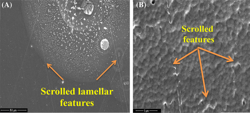
When the polymer with FSWCNT-4 is subjected to ultrasonication (PFSn-0.1-US-VD), the spherulite structure is suppressed with the formation of scrolled lamellar features as shown in two different magnifications Figure 13A,B. Due to ultrasonication, the PVDF spheres unite to form a compact morphology with a distinct crystallization pattern. The FSWCNT-4 serves as nucleation sites for the formation of scrolled lamellar pattern of crystallization in the films as is evident in Figure 13B. The scrolled lamellar structures formed causes diffusion of PVDF chains on to FSWCNT-4 thus enabling a proper stacking between the polymer chains.36-49
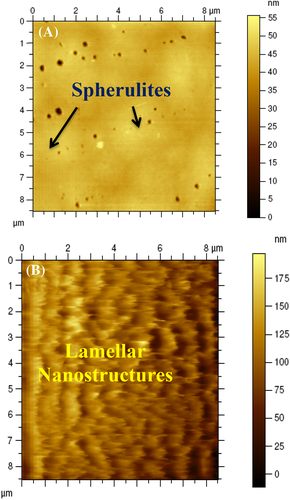
The morphologies are further analyzed using AFM. The spherulitic morphology is evident here as well for PFSn-0.1-VD (Figure 14A). On the other hand, PFSn-0.1-US-VD has scrolled lamellar patterns on the surface of dense compact morphology as illustrated in Figure 14B thus complementing the FESEM images. This is the reason for the formation of well oriented microstructure in these nanocomposites.
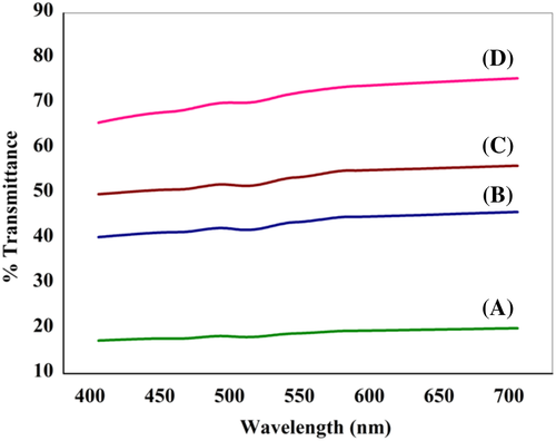
The nanocomposites prepared without and with ultrasonication show clear difference in optical transmittance. Results of measurements of optical transmittance of all the nanocomposite films are shown in Figure 15. The UV-Vis spectra show that transmittance in the visible region of the nanocomposites is much higher for films where the polymer is subjected to ultrasonication prior to vacuum drying, in comparison to that prepared without ultrasonication. For PFSn-0.1-US-VD, the dispersion of FSWCNT-4 is better achieved with ultrasonication followed by controlled evaporation of the solvent under vacuum conditions leading to morphology with distinct crystallization patterns like scrolled lamellar features and better interaction.37-50 These factors imply a better optical transmittance in this film compared to that prepared without ultrasonication (PFSn-0.1-VD). Thus, similar to neat PVDF film, ultrasonication followed by vacuum drying aids in better optical transparency for FSWCNT-4 incorporated film. Since there is a difference in transparency for PFSn-0.01-US-VD, PFSn-0.05-US-VD, and PFSn-0.1-US-VD, the crystalline phases of the polymers are to be analyzed in detail using XRD and to be compared with that of PFSn-0.1-VD.
The role of processing parameter as well as the effect of FSWCNT-4 on the phase morphology of PVDF is investigated by XRD, FTIR, and Raman spectroscopic analyses. Figure 16 shows the XRD spectra of the nanocomposite films. PFSn-0.1-VD shows four characteristic diffraction peaks at 17.7, 18.4, 20.3, and 26.6°, which are assigned to (100), (020), (201), and (021) reflections of the α phase crystals confirming dominant nonpolar phase in PFSn-0.1-VD. All the other nanocomposites where the polymer is subjected to ultrasonication prior to vacuum drying shows characteristic peak of γ phase at 18.5 (020) and 20.3 (101). It is known that the polar γ phase and the nonpolar α phase crystal planes have an almost same XRD peaks. The γ phase crystal planes at 020 and 101 overlap with the 020 and 201 crystal planes of α phase.38-51 Therefore, it is complex to identify whether the nanocomposites prepared after ultrasonication followed by vacuum drying contains the α phase. However, it is evident from Figure 17 that the characteristic peak at 17.7° (100) disappears for all the three nanocomposites prepared through ultrasonication indicating a significantly decreased α phase content in these films. This is further confirmed by the FTIR analysis results.
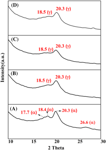
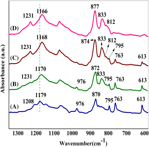
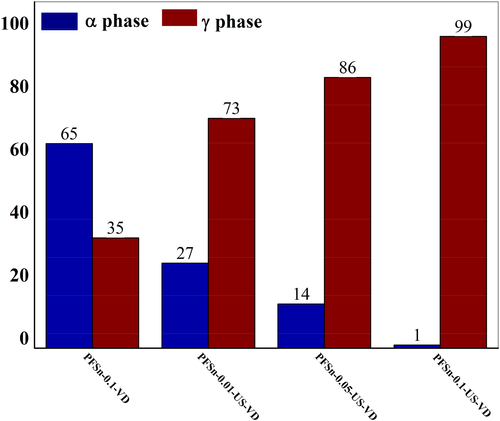
Figure 17 shows the FT-IR spectra of the nanocomposite films. For PFSn-0.1-VD, the characteristic peaks at 613, 769, 795, 976, and 1208 cm−1 are ascribed to the α phase which is in agreement with XRD results. However, when the polymer is subjected to ultrasonication, relatively strong absorption peaks at 812, 833, and 1231 cm−1 which are assigned to γ phase are observed. The incorporation of different concentrations of FSWCNT-4 into the PVDF matrix followed by ultrasonication assisted vacuum drying induces significantly increased fraction of γ phase with relatively deceasing intensities of peaks corresponding to α phase. The relative fraction of γ phase, [F (γ)] in various nanocomposites is calculated using Equation (1) and is shown in Figure 18. It is seen that 0.01 wt% of FSWCNT-4 in PVDF (PFSn-0.01-US-VD) induces about 73% γ phase crystals and the fraction increases with increasing FSWCNT-4 loading in the nanocomposites with the highest γ phase fraction obtained for 0.1 wt% of FSWCNT-4 (99%) that is, for PFSn-0.1-US-VD. However, for the nanocomposite which is prepared without ultrasonication (PFSn-0.1-VD), the fraction of γ phase is only 35%, confirming the combined effect of ultrasonication and carbon nanotube in inducing the polar phase in PVDF nanocomposites. This difference in the fraction of γ phase in nanocomposites directly relates to the difference in optical transmittance in them as already shown in Figure 15. It is reported that the presence of γ phase in PVDF films increases transparency and hence are suitable for optical applications.39-52 Thus, in the present study, a new technique of increasing the optical transparency in PVDF films by the addition of different concentrations of functionalized nanotubes is introduced. Thus controlled processing conditions viz. ultrasonication assissted vacuum drying along with proper dispersion of functionalized nanotubes in PVDF induce polar γ phase which aids in optical transparency along with enhanced electrical and mechanical properties.
FTIR spectra given in Figure 17 also indicates that the stretching vibration of –CF2, which appears at 1179 cm−1 in PFSn-0.1-0-VD is shifted to lower side for all the nanocomposites prepared through ultrasonication followed by vacuum drying. This shift is an indication of the enhancement in the contacts between –CF2 groups in PVDF and the π electrons on the exterior of CNTs as a result of ultrasonication assisted vacuum drying.38-51 Similarly, clear evidence on the contact between the –CF2 groups in PVDF and the reactive groups of CNTs (carboxyl and hydroxyl functionalities) is seen in the bending vibration of –CF2. In PFSn-0.1-VD (no ultrasonication, but presence of 0.1 wt% FSWCNT), the bending vibration of –CF2 appears at 870 cm−1 and is shifted to 877 cm−1 for the nanocomposites, which are prepared through ultrasonication assisted vacuum drying. All these evidences substantiate the formation of a donor-acceptor complex that exists between the fluorine groups in PVDF which acts as the electron acceptor species due to its electrophilic nature with the electron rich carboxylic and hydroxyl groups of FSWCNTs in inducing γ phase formation through the process of ultrasonication assissted vacuum drying.40-53
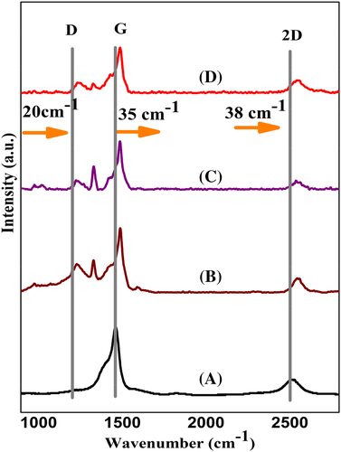
Raman spectroscopy is employed to confirm the formation of donor-acceptor complex in the nanocomposites. The spectra are given in Figure 19 for all the ultrasonicated nanocomposites with different weight loadings of FSWCNT-4 along with the spectrum of functionalized nanotube. The positions of G, D, and 2D bands are shown in Supporting Information ESI. Results of Raman spectroscopy analysis show that the G-band or the graphitic band at 1562 cm−1 for FSWCNT-4 shows an upshift of 35 cm−1 while the D band located at 1322 cm−1 which corresponds to multiple phonon scattering of defects or amorphous carbon in FSWCNT-4 shows an upshift of 20 cm−1 when these are incorporated in the PVDF matrix. Similarly, the 2D band at 2653 cm−1 shows upshift of 38 cm−1. The upshift of G, D, and 2D band peaks is an indication of the interaction between PVDF chain and FSWCNT-4 apparently as a result of the development of donor-acceptor complexes which is initiated through ultrasonication assisted vacuum drying process.41-54
Formation of γ phase which has different crystalline morphology compared to α phase is further confirmed by DSC measurements. DSC heating and cooling curves of PFSn-0.1-VD (where the polymer is not subjected to ultrasonication) and PFSn-0.1-5-VD are given in Supporting Information. The enthalpy changes for crystallization of all the nanocomposites have been calculated using Equation (2), and are shown in Table 5. The crystallization temperature (TC), enthalpy of crystallization (ΔHc) and percentage crystallinity [XC (%)] for the FSWCNT-4 incorporated PVDF which is subjected to ultrasonication prior to vacuum drying increase with increasing content of FSWCNT-4. With the change in processing conditions that is, vacuum drying alone and ultrasonication followed by vacuum drying, the latter shows a gradual shift in the crystallization peak to higher temperatures for the nanocomposites. Under the same processing condition (ie, ultrasonication followed by vacuum drying), the crystallization peak increases with increase in the concentration of FSWCNT-4. This indicates that, controlled processing together with nucleating effect of FSWCNT-4 help in the easier crystallization of PVDF to form films with predominantly γ phase.
| Film | FSWCNT-4 content (wt %) | TC (°C) | ΔHC (J/g) | XC (%) |
|---|---|---|---|---|
| PFSn-0.1-VD | 0.1 | 135.44 | 38.8 | 37.1 |
| PFSn-0.01-5-VD | 0.01 | 135.69 | 40.05 | 38.3 |
| PFSn-0.05-5-VD | 0.05 | 136.72 | 43.5 | 41.6 |
| PFSn-0.1-5-VD | 0.1 | 137.52 | 50.4 | 48.2 |
- Abbreviations: ΔHC, enthalpy of crystallization; TC, crystallization temperature; XC, percentage.
As described earlier for unfilled PVDF films, the nanocomposite films also exhibit improvement in electrical and mechanical properties with respect to the process conditions adopted. It would be worthwhile to compare such properties of the unfilled and SWCNT incorporated films to understand the specific role of functionalized SWCNTs. The capacitance values together with the percentage of γ phase of all the nanocomposites are shown in Table 6. There is a direct relationship between electrical properties of the films and the percentage of γ phase present in them, which in turn related to the processing parameter. The capacitance of PFSn-VD, having a γ phase fraction of only 35 is 468.6 pF. However, for the nanocomposite films prepared through ultrasonication assisted vacuum drying process, the capacitance increases with increasing FSWCNT-4 content. The capacitance of films increases from 523.1 pF for 0.01 wt% of FSWCNT-4 to 980.9 pF for 0.1 wt% of FSWCNT-4. This is attributed to the efficient processing of nanocomposites, which enhances the nucleation effect of FSWCNT-4 thus crystallizing the PVDF films in polar γ phase leading to an increase in its electrical properties. With increase in the FSWCNT-4 content better nucleation is achieved for the PVDF matrix as confirmed from the fraction of γ phase. Ram et al.42-55 reported improvement in electrical properties of PVDF with the incorporation of multiwalled carbon nanotube (MWCNT) where significant improvement in DC conductivity is achieved with incorporation of minimum 1 wt% MWCNT whereas in the present study, significant electrical conductivity is reached with 0.1 wt% SWCNT.
| Sample | F(γ)% | Capacitance (pF) | Modulus (MPa) | Tensile strength (MPa) | Elongation at break (%) |
|---|---|---|---|---|---|
| PFSn-0.1-VD | 35 | 468.6 ± 3.6 | 1313 ± 7 | 31 ± 0.8 | 4.9 ± 0.04 |
| PFSn-US-VD-0.01 | 73 | 523.1 ± 4.5 | 1575 ± 3 | 33 ± 0.7 | 4.6 ± 0.05 |
| PFSn-US-VD-0.05 | 86 | 741.1 ± 6.7 | 1758 ± 4 | 36 ± 0.5 | 4.2 ± 0.08 |
| PFSn-US-VD-0.1 | 99 | 980.9 ± 5.9 | 2145 ± 6 | 44 ± 0.9 | 3.7 ± 0.07 |
Mechanical properties of all the nanocomposite films, which are subjected to different processing conditions are given in Table 6. It is evident that the mechanical properties change with change in processing conditions as well as change in the concentration of FSWCNT-4. The nanocomposite films prepared through ultrasonication assisted vacuum drying show an increase in modulus and tensile strength in comparison to the film prepared without ultrasonication. As already described, the influence of processing parameters in the preparation of nanocomposites is evident in the mechanical properties. The thermal energy produced during ultrasonication is capable of crossing the energy barrier between the α and γ phases and thus transforming into the polar phase for those nanocomposites prepared through ultrasonication assisted vacuum drying. The phase change is established from the microstructure of the nanocomposites prepared through different processing conditions. PFSn-0.1-VD show fused spherulites with dendritic patterns, which are characteristics of α polymorphic structure (Figure 12). On the other hand, PFSn-0.1-US-VD displays formation of scrolled lamellar features with dense and smooth film which are characteristics of γ phase morphology (Figure 13). Thus, the mechanical performance of the films depends on the processing conditions for the preparation of nanocomposite films. In addition, under the same processing condition of ultrasonication assisted vacuum drying, the mechanical properties depend on the concentration of FSWCNT-4. With increase in the concentration of FSWCNT-4, better nucleation as well as good nano level dispersion is achieved resulting in an increased formation of polar phase and improved mechanical properties for PFSn-0.1-US-VD in comparison to lower weight loadings of 0.01 and 0.05 wt% of FSWCNT-4. The role of nanotube in improving the electrical and mechanical properties of the films is evident on comparing the properties given in Table 3 (for unfilled films) with those given in Table 6 (for nanotube incorporated film). Even without ultrasonication, presence of nanotube increases the capacitance value from 245 to 467 pF (90% increase) with an increase in tensile strength from 29 to 31 MPa (P-VD in Table 3 vis-à-vis PFSn-0.1-VD in Table 6). The increase in capacitance with ultrasonication in the absence of FSWCNT is 74% (P-VD vis-à-vis P-US-VD in Table 3) whereas the increase in presence of FSWCNT (PFSn-0.1-VD vis-à-vis PFSn-US-VD-0.1 in Table 6), the increase is 109%. Mechanical properties also show similar trend here. That is, in order to increase the electrical and mechanical properties, both ultrasonication and presence of nanotube are required.
The type of drying conditions of the nanocomposites also influences the mechanical performance of the films. To compare the effect of drying conditions, similar to the air-dried PVDF films described in the previous section, nanocomposite films have also prepared through air drying process. The air-dried film where the polymer is not subjected to ultrasonication is denoted as PFSn-0.1-AD and the other one where the polymer is subjected to ultrasonication followed by air drying is denoted as PFSn-0.1-US-AD. Results of FTIR, XRD, Raman spectroscopic, and FESEM analyses of the films are shown in Supporting Information. The air-dried film (no ultrasonication for the polymer solution) crystallized in α phase while the one prepared through ultrasonication assisted air drying crystallized in γ phase. The mechanical properties of these films are compared with those of P-VD and P-US-VD (where the films are subjected to vacuum drying). The variation of tensile strength and modulus for the four different films prepared under different process conditions are given in Figure 20. The tensile strength and modulus of PFSn-0.1-VD show an increase of 182% and 202% respectively in comparison to PFSn-0.1-AD while PFSn-0.1-US-VD shows an enhancement of 33 and 48%, respectively in comparison to PFSn-0.1-US-AD.
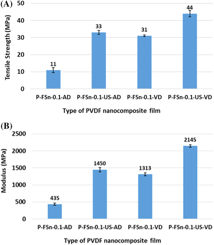
To explain the mechanical properties of these nanocomposites, its morphology together with phase changes need to be understood. It is observed that PFSn-0.1-AD has porous spherulitic morphology which causes a decrease in the mechanical properties in comparison to PFSn-0.1-0-VD which has fused spherulites even though both crystallizes in the α polymorphic structure. Further, PFSn-0.1-US-AD shows scrolled lamellar features whereas its vacuum dried counterpart, PFSn-0.1-US-VD show scrolled lamellar features together with dense smooth film. Here, the latter shows significant improvement in mechanical properties which is attributed to the controlled processing parameter leading to the formation of dense smooth mechanically strong nanocomposite film, even though both crystallize in polar γ phase. Thus, the type of processing technique adopted causes morphological changes in the film, which in turn determine the mechanical properties.
The phase separation mechanism discussed for unfilled PVDF films under Section 3.1. is applicable for PVDF/FSWCNT-4 nanocomposite as well, which are prepared by different processing conditions viz. air drying (PFSn-0.1-AD), vacuum drying (PFSn-0.1-VD), and ultrasonication followed by vacuum drying (PFSn-0.1-US-VD). The morphology of these nanocomposites is also determined by the phase diagram given in Figure 10B which is used for explaining the changes in the unfilled PVDF films.
Figure 21 shows the FESEM images of the nanocomposites prepared through different processing conditions. PFSn-0.1-US-VD, shown by orange colored outline in Figure 21A, has a smooth and compact morphology as a result of controlled processing condition viz. ultrasonication followed by vacuum drying. Thus similar to the phase diagram shown in Figure 10B, this film does not cross the binodal region. However, the microstructure evolution of PFSn-0.1-VD, denoted by pink colored outline (Figure 21B) has fused spherulites which occur in the metastable region between binodal and spinodal. For PFSn-0.1-AD, shown by brown colored outline (Figure 21C) display loosely connected porous spherulitic morphology, which falls in the unstable region of the phase diagram.
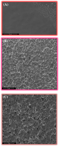
Thus, phase separation mechanism, which is well demonstrated for PVDF membranes and PVDF thin films, is applicable to PVDF/FSWCNT-4 nanocomposites as well. Similar to those observed for unfilled PVDF films, for the fabrication of high optical quality smooth nanocomposites with superior mechanical and electrical properties, the suggested processing condition is ultrasonication followed by vacuum drying. The study also reveals that nanocomposites prepared under air-drying and vacuum drying conditions without ultrasonication are cloudy and rough. The three nanocomposites prepared by different processing conditions show different phases as studied from various spectroscopic analysis. Air dried (details are given in Supporting Information ESI) and vacuum dried nanocomposites (Figure 17) crystallize in the nonpolar α phase while ultrasonication followed by vacuum drying process (Figure 17) produce film with almost 99% polar γ phase. The energy provided by ultrasonication triggers FSWCNT-4 to act as an efficient nucleating agent through proper dispersion in the PVDF matrix resulting in conformational changes while the controlled evaporation of the solvent by vacuum drying produces optically clear films as seen for PFSn-0.1-US-VD.
4 CONCLUSIONS
Optically transparent PVDF thin films and PVDF/FSWCNT-4 nanocomposites have been fabricated by ultrasonication followed by vacuum drying process. For comparison, films without ultrasonication were also processed, subjecting them to vacuum drying. Films prepared through the former procedure crystallized in the polar γ phase while the latter crystallized in nonpolar α phase. The morphology of the films originated from VIPS, a common process adopted for the fabrication of PVDF membranes. Under conditions of ultrasonication followed by vacuum drying, there is no solvent (water); hence no separation of phases occur here enabling the films to be smooth and compact with high optical transparency. However, when the films are subjected vacuum drying without subjecting the polymer solution to ultrasonication, the compositional path crosses binodal in the phase diagram. Here liquid-liquid demixing occurs with an expansion as well as nucleation in its morphology forming cloudy films with α phase. Comparison of these films with air-dried films is also carried out. Air-drying of PVDF films and PVDF/FSWCNT-4 nanocomposites results in spinodal phase separation followed by subsequent crystallization to α phase with loosely connected porous spherulitic particles. This study demonstrates a simple and quick method of ultrasonication followed by vacuum drying for the preparation of optically transparent and mechanically strong PVDF films, both plain and carbon nanotube filled. Controlled processing conditions also lead to the formation of mechanically strong and electrically active films and composites. The role of optimally functionalized SWCNT (FSWCNT-4) in bringing out the phase morphology and optical transparency in PVDF films further validates the utility of the modified filler for use in microelectronic applications. Incorporation of optimally functionalized carbon nanotubes enhances the chances of formation of polar γ phase with much improved electrical and mechanical properties compared to its unfilled counterparts.
ACKNOWLEDGMENTS
The authors thank Director, Vikram Sarabhai Space Centre (VSSC) for permission to publish this work and colleagues in Polymers and Special Chemicals Division and Analytical and Spectroscopy Division, VSSC for their support. One of the authors (Rinu Elizabeth Roy) is thankful to Indian Space Research Organization (ISRO) for the research fellowship.


