A patient-friendly 16-channel transmit/64-channel receive coil array for combined head–neck MRI at 7 Tesla
Funding information: This work was supported by the National Institutes of Health (NIH), grants 5R01EB006847, 1P41EB030006, 1S10OD023637; and the Federal Ministry of Education and Research Germany (BMBF), grant IN2016-2-226.
Click here for author-reader discussions
Abstract
Purpose
To extend the coverage of brain coil arrays to the neck and cervical–spine region to enable combined head and neck imaging at 7 Tesla (T) ultra-high field MRI.
Methods
The coil array structures of a 64-channel receive coil and a 16-channel transmit coil were merged into one anatomically shaped close-fitting housing. Transmit characteristics were evaluated in a B1+-field mapping study and an electromagnetic model. Receive SNR and the encoding capability for accelerated imaging were evaluated and compared with a commercially available 7 T brain array coil. The performance of the head–neck array coil was demonstrated in human volunteers using high-resolution accelerated imaging.
Results
In the brain, the SNR matches the commercially available 32-channel brain array and showed improvements in accelerated imaging capabilities. More importantly, the constructed coil array improved the SNR in the face area, neck area, and cervical spine by a factor of 1.5, 3.4, and 5.2, respectively, in regions not covered by 32-channel brain arrays at 7 T. The interelement coupling of the 16-channel transmit coil ranged from −14 to −44 dB (mean = −19 dB, adjacent elements <−18 dB). The parallel 16-channel transmit coil greatly facilitates B1+ field shaping required for large FOV neuroimaging at 7 T.
Conclusion
This new head–neck array coil is the first demonstration of a device of this nature used for combined full-brain, head–neck, and cervical-spine imaging at 7 T. The array coil is well suited to provide large FOV images, which potentially improves ultrahigh field neuroimaging applications for clinical settings.
1 INTRODUCTION
Ultra-high field (UHF) 7-Tesla (T) MRI is rapidly evolving both in technology and in the potential for medical and scientific applications. There is a growing need for clinical 7 T neuroimaging to provide combined head and neck imaging to match the standard of care at 1.5 and 3 T for the assessment of a variety of neurodegenerative diseases.1, 2 The capabilities of combined full-brain, neck, and cervical spinal MRI have proven valuable in obtaining more insights into many neurodegenerative diseases, such as multiple sclerosis3, 4 and amyotrophic lateral sclerosis.5 However, the ability of this technique to detect subtle pathologic characteristics is severely limited by the contrast-to-noise ratio and the spatial resolution of current clinical systems.6
For susceptibility-based contrast in particular, UHF imaging at 7 T affords advantages in SNR and contrast-to-noise ratio, which can then be traded off for increased spatial resolution and higher SNR.7 This improvement in diagnostic power has been proven valuable, especially in the identification of small lesions that are not noticeable at standard MRI field strengths.8, 9 To address these clinical needs of combined head–neck imaging at 7 T, dedicated RF coils are required that enable transmission and reception for a considerably larger FOV than existing 7 T brain-only coils. Current state-of-the-art 7 T head, neck, and cervical-(C)-spine imaging necessitates a change of coil for imaging either brain and head areas or the neck/C-spine region.
UHF-7 T scanners currently utilize up to 64 receive (Rx) channels. Although originally proposed for increasing SNR,10 the use of simultaneous reception with multiple coils to speed up the image encoding has proven critical for improving 7 T image quality.11 Particularly in single-shot fMRI, highly parallel array coil technology and accelerated parallel image encoding offer the possibility of considerable reduction in echo spacing, encoding time, and the related mitigation of image distortions and intensity dropouts associated with macroscopic susceptibility gradients in UHF-fMRI. This need has been met by the introduction of commercial 7 T 24-channel and 32-channel Rx brain array coils,12, 13 and more recently, coil array hardware studies have exploited the benefits and potential of close-fitting 64-channel 7 T brain arrays.14 Dedicated 7 T coils for C-spine imaging are limited in their commercial availability and have been overall less technologically studied than 7 T brain-only array coils. Most of the proposed 7 T C-spine coils are designed on an anatomically shaped close-fitting coil former to be placed on the posterior side of the neck.15-17 Recently, a 22-channel C-spine array coil showed improved SNR by fully encircling the neck region.18 Combining head and neck imaging at 7 T is challenging due to multiple factors, including transmit (Tx) (B1+) nonuniformity, main magnetic field (B0) inhomogeneity, and the complexity in optimizing Tx–Rx RF coil array strategies. In particular, B1+ inhomogeneities caused by the decreased RF wavelength at 7 T need to be compensated by integrating parallel Tx (pTx) elements combined with excitation methods, such as B1+ shimming,19 tailored pTx pulses,20, 21 or spoke pTx pulses with combined simultaneous multislice acquisition.22 When both pTx and high-density Rx arrays are employed for UHF imaging, the Tx–Rx functionality is usually mechanically separated into 2 housing segments, where a close-fitting head former houses the receivers, whereas the Tx structure is housed in a separate sliding tubular former and pulled over the subject's head.23-26 In addition to adding a step not needed in 3 T scanning, the cylindrical structure has limited Tx efficiency in the neck due to the distance of the elements. Clément et al. merged the mechanically separated coil housings and showed an 8-channel Tx/32-channel Rx brain-only array that was optimized for a highly space-constrained head gradient system at 7 T.27 The Tx and Rx structure was integrated into an anatomically conformal coil housing.
In this study, we designed, constructed, and validated a 7 T head–neck array coil aimed at mimicking the form factor of a 3 T head–neck array. We implemented an UHF head–neck coil for which the Rx and Tx elements were merged into one anatomically shaped close-fitting housing, without the need of the external cylindrical Tx housing. Similar to 3 T head–neck arrays, the coil housing is splittable to allow an easy entry for the patient. We evaluated the constructed array coil for head–neck and C-spine imaging performance using SNR and geometry-factor (G-factor) maps. For brain imaging, we compared it directly to a commercially available 8-channel Tx/32-channel Rx brain-only array. We demonstrated the coil's capability in highly accelerated anatomical images and evaluated the suitability for simultaneous UHF imaging of the brain and C-spine cord.
2 METHODS
2.1 Coil design and construction
The coil was designed on an anatomically shaped former consisting of a large posterior head–neck part and an overlapping anterior head–neck portion (Figure 1A,B). The mechanical implementation of the housing split has been shown26 at 3 T and was implemented in this project.
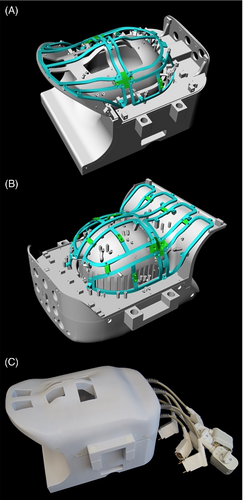
CAD, computer-aided design; ch, channel; Rx, receive; Tx, transmit.
The head–neck coil contour is based on the 96 percentiles of the male head circumferences,28 which allows to accommodate nearly all human subjects. The general dimension of the inner coil former in the superoinferior, anteroposterior, and left–right direction was restricted to 382 cm, 252 mm, and 195 mm, respectively.29 We used computer-aided design software program (Rhino3D V.6.0, Robert McNeel & Associates, Seattle, WA, USA) to 3D-model both array coil housings.
The housing of the anterior head–neck portion includes 24 Rx and 8 Tx elements, and the larger posterior head–neck section comprises 40 Rx and 8 Tx elements. The larger posterior section is designed so that the subject can lie down into the coil rather than using a helmet design, which must be pulled down over the head. A locking mechanism was incorporated to mate the anterior and posterior head coil segments. The Rx and Tx structures were merged into one housing instead of implementing a commonly used separate tubular housing (Figure 1C). Therefore, the Tx structure also follows the anatomical shape of the head and neck region. Patient comfort was considered by incorporating large mouth and eye cutouts. The latter facilitates visual stimulation for functional MRI studies. Additionally, a hole for cables between the anterior and posterior segments was implemented at the superior coil end to enable combined electroencephalogram studies.
All helmet parts were 3D-printed in polycarbonate plastic (Fortus 450, Stratasys, Eden Prairie). The 3D printed materials were not further treated (e.g., primed or painted). The total weight of the constructed head–neck coil, including its electronics and plugs, amounts to 11.3 kg. The posterior and anterior segments individually weigh 6.2 and 5.1 kg, respectively.
An anthropomorphic head–neck phantom was constructed with PA12 plastic using laser sintering 3D-printing technology. The phantom was filled with agar gel,30 which mimics the average dielectric properties of human muscle tissue at the Larmor frequency of 297.2 MHz.31 The conductivity and relative permittivity of the phantom were measured to be σ = 0.75 S/m and εr = 58.2, respectively, using a dielectric measurement kit (DAK, Schmid & Partner Engineering AG, Zurich, Switzerland).
2.2 Simulation
A simulation-guided design approach of the 16-channel Tx array was carried out by full-wave electromagnetic analysis using finite element modeling (high-frequency structure simulator (HFSS) Ansys Electronics Desktop 2021 R1, ANSYS Inc., Canonsburg, PA). The simulations were carried out using a high-performance computing server (PowerEdge R740xd, Intel Xeon Gold 6140 CPU 2.30GHz 36 Cores 1.5 TB RAM, Dell Technologies Inc, Round Rock, TX). Simulation time for the fully tuned, decoupled, and adjusted Tx coil array model was approximately 2 days for the single-compartment head and neck model and 3 days for the multi-tissue HFSS human body model in order to generate all field maps.
The digital version of the head–neck loading phantom was imported into HFSS, and the dielectric parameters were matched to the real values. The Tx structure model included all construction details, including precise dimensions and electrical material properties. All Tx elements were modeled with the 3D computer-aided design software and imported into HFSS. The loop conductor material was defined as copper (σ = 5.8·107 S/m) in HFSS. Each channel of the Tx array was excited using a 1 V rms sinusoidal continuous RF wave at the Larmor frequency of 297.2 MHz (7 T) for obtaining the B1+ efficiency maps of individual Tx elements. To determine the specific absorption rate (SAR) in the circularly polarized (CP) configuration, an input power of 1 W was applied on the total simulation. In addition, all 16 Tx ports were connected to a 0.07 dB attenuator in the RF co-simulation to account for the cable loss from the coil's feed port to the coil plug.
All discrete RF components (capacitors and inductors) were defined as variable lumped ports in the HFSS computational model in order to allow them to be tuned in the circuit simulator. At the initial step, we simulated each individual loop element to derive the needed capacitors for tuning and matching using an RF co-simulating approach.32 Decoupling networks between adjacent Tx elements were emulated using a resonant inductive decoupling (RID) circuitry method.33 The complex excitation profile of each coil was taken as the B1+ component of the simulated magnetic field. Because the anatomical conformal 16-channel dual-row Tx coil is not of a purely cylindrical design, we obtained required phases for the CP mode by the actual radially given geometric angular increments of the elements. In addition to the regular CP shim mode, we also evaluated a the CP2+ shim configuration (90° phase increments).
The capacitor values of the Tx array were determined in a two-step simulation approach: First, we simulated, tuned, and matched the array to obtain the values of the required capacitors. In the second step, the simulated capacitors values were chosen to match the closest discrete value from the standard capacitor kit. To allow tuning and matching, one variable tuning capacitor and two variable matching capacitors were implemented in each Tx coil element model. Based on the simulated lumped elements values, the Tx coil was then constructed and bench-top-validated (Figure 2).
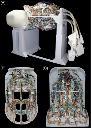
Due to the geometrical and electrical complexity, the Rx array was not incorporated in the simulation. For realistic SAR simulations, a multi-compartment human dielectric equivalent head–neck model was used (HFSS, ANSYS Inc., Canonsburg, PA).34
Local SAR maps (SAR averaged over 10 g of tissue, - IEC/IEEE 62704–4 standard) of the head–neck human model were used to create Q-matrices in MatLab (MathWorks, R2019b Natick, MA). The Q-matrices were compressed into a set of 2866 virtual observation points35 with an SAR overestimation factor of 5% of the worst possible local SAR. The virtual observation points were used on the scanner to calculate the maximum local SAR for any complex excitation. A 2.5-fold safety factor was added to the local SAR matrices to account for subject anatomic variability, coil modeling inaccuracies, uncertainties in the MRI scanner RF monitoring system, and overall conservative estimate of local SAR for the initial in vivo scans.36, 37
2.3 Rx array
The 64 Rx elements were made from 0.5 mm-thick semiflexible FR4 printed circuit board (PCB) material and mounted on the head–neck coil former. The PCB of the Rx structure was externally manufactured (Beta LAYOUT GmbH, Aarbergen, Germany). A single PCB sheet was designed for each anterior and posterior segment to adequately wrap the Rx coil array structure around the coil former. The geometrical loop layout used a mixture of overlapped elements38 and a shared capacitance degenerately decoupled design39 (Figure 3). Depending on the loop diameter, we subdivided each element symmetrically with six and eight gaps for small and large loop sizes, respectively. The coil's output circuit comprised a capacitive voltage divider (Series 11, Knowles Capacitors, Norwich, UK) and a variable series capacitor (GFX2700NM, Sprague Goodman, Westbury, NY) to impedance match the element's output to an optimized noise match of 75 Ω. Additionally, the output circuit board used an active detuning circuitry across one of the voltage divider capacitors. Active detuning during transmit was achieved using a PIN diode D1 (MA4P4002B-402, Macom, Lowell, MA) in series with a tunable inductor LACT (150-02J08L, CoilCraft Inc., Cary, IL), which together with capacitor CT3 resonated at the Larmor frequency. Thus, when the PIN diode D1 is forward-biased (Tx mode), the resonant parallel LACTCT3 circuit inserts a high impedance in series with the coil loop, blocking current flow at the Larmor frequency during transmit. For further enhancement of coil safety, a passive detuning circuit was implemented comprised of a cross-diode Dx (MADP-011048TR3000, Macom, Lowell, MA), the RF-choke LRFC2 (1812CS-272, CoilCraft Inc., Cary, IL), and the capacitor CD. The latter tunes out the increased inductance due to the slightly elongated copper trace of the passive detuning circuitry path.
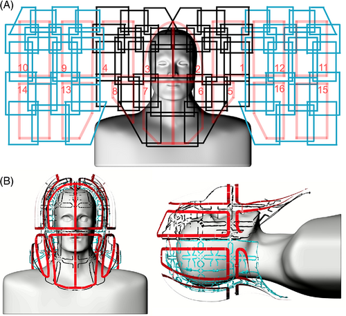
Preamplifier decoupling was established to transform the preamplifier input impedance (11.2 + j10.4) Ω to a high series impedance within the loop.10 The preamplifier's daughterboards were mechanically mounted on the helmet via 3D-printed plastic standoffs. All preamplifiers (Siemens Healthineers AG, Erlangen, Germany) were carefully oriented in the z-direction to minimize Hall effect issues.40-42 We used the impedance change of the series matching capacitor to transform the input impedance of the preamplifier to a parallel inductance across CTM1 of the capacitive voltage divider. This parallel LC circuit resonated at the Larmor frequency and induced the needed high serial impedance into the coil loop. Thus, minimal current flowed in the loop. and inductive coupling to other coils was minimized despite the presence of residual mutual inductance.
2.4 Tx array
The 16-channel Tx array was anatomically shaped and mounted on the same Rx head–neck coil former while maintaining an offset of 3 cm to the Rx structure. The superior eight channels were shaped to conform anatomically along the head. The eight elements on the inferior ring were shaped to follow the neck and shoulder coil frame. The Tx loop element arrangement was laid out in a stacked dual row design with eight elements per row. The Tx array was also constructed using the 0.5 mm-thick semiflexible FR4 PCB material (0.5-Cu-35/0, Masterplatex e.K., Schönwalde-Glien, Germany), which was installed on the Tx rail mounting system. The Tx loop elements were separated with a 2 cm gap, and only the element pairs over the eyes and mouth shared a common conductor path and its series capacitors. This configuration enlarged eye and face cutouts in the coil housing to allow improved patient comfort. The circuit schematics for a representative Tx–Rx element are shown in Figure 4. Based on the electromagnetic simulation, we distributed series tuning capacitors (Series 11, Knowles Capacitors, Norwich, UK) every 3 cm. A variable high-power capacitor (60–0716-10 016-600; Tronser, Engelsbrand, Germany) was incorporated to adjust each element to the Larmor frequency. We used two symmetric matching capacitors CM2 to transform the Tx loop's impedance to 50 Ω. A series PIN diode D2 (MA4P7470F-1072 T, Macom, Lowell, MA) was placed in each loop. Thus, the Tx elements had to be actively tuned by forward biasing the PIN diode while leaving the Tx loop off-resonance during reception. The bias for the PIN diode was supplied through an RF choke (1812CS-272, CoilCraft Inc., Cary, IL). To drive the 16 Tx loops, a bazooka balun was used before the 50 Ω matching network.
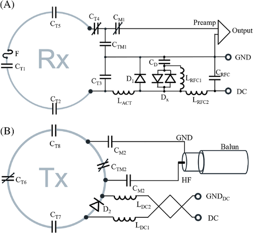
CM2, two matching capacitors.
Adjacent Tx loops with the 2 cm geometrical gap were decoupled by incorporating a RID network33 (Supporting Information Figure S1). This method also worked out for the adjacent element pairs that were placed at the two separated coil housing segments, where the decoupling inductor from one Tx element faces the oppositely wound inductor of the neighboring Tx element through the housing plastic wall. To enable a reliable alignment of this cross-housing coupling structure, the anterior coil segment closes the helmet via a snap-in mechanism and two bolt locks. Loop pairs with the shared conductor (eyes and mouth area) were tuned to degeneracy by correctly choosing the rung and loop capacitance to achieve sufficient decoupling.43
In the free spaces between the Tx structure and Rx structure, we installed the preamplifiers. Thus, the Tx and Rx structures share the same area of the coil former rather than exist as separate functionalities in two independent housings.
2.5 Coil bench measurements
The constructed Rx and Tx array coils were adjusted and optimized with a battery of standardized RF bench level metrics. These bench measurements verified the element tuning, active detuning, nearest-neighbor coupling, and preamplifier decoupling for each coil element. Prior to cable routing, we assessed the unloaded-to-loaded quality factor ratio (QUL/QL) of the Rx elements using the S21 double-probe method.44 For this measurement, the actively detuned nonresonant neighbors were present, including the detuned Tx structure. Also, the frequency shift upon phantom loading was measured with the S21 double probe. After installing the cables, we used a custom-made coil plug simulator to control each Rx channel's detuning bias and to power the preamplifiers. All elements were pretuned to resonate at the Larmor frequency. The active detuning circuitry was adjusted by carefully controlling the variable inductance L of the active detuning circuit under an S21 double-probe measurement. For fine adjustments, each loop under testing was brought into the tuned state, whereas all neighboring elements were actively detuned. By performing an S11 measurement on a vector network analyzer in combination with an RF switching matrix (ZNB8, ZN-Z84, Rohde & Schwarz, Memmingen, Germany), we tuned and matched the Rx coil elements to 75 Ω at the Larmor frequency under a loaded condition. With the RF switch matrix, up to 24 channels could monitored simultaneously.
Nearest neighbor coupling was measured using a direct S21 measurement between pairs of elements using coaxial cables directly connected to the preamplifier sockets of the 2 elements under testing. When measuring the S21 between an adjacent pair, all other elements of the array were detuned. We measured the preamplifier decoupling of a given loop with all other loops detuned. Preamplifier decoupling was measured as the change in the double-probe S21 when the preamplifier socket was terminated in each of 2 different match conditions: In the first case, the coil was terminated with the powered low-impedance preamplifier. In the second case, the coil was terminated by 75 Ω.
The 16-channel Tx coil array was tuned under phantom loading to the Larmor frequency and matched to the 50 Ω system impedance to provide power-matched conditions. The decoupling was optimized by performing a direct S21 measurement between adjacent Tx elements, whereas the RID networks were adjusted to provide a sufficient interelement decoupling of <−16 dB. Additionally, the QUL/QLratio for each Tx element was obtained when the coil element was placed within the populated but detuned array. The bazooka baluns at each Tx coaxial cable were measured with an S21 current injection RF probe.45 Potential variations in tuning, matching, and coupling due to differently sized loading conditions were bench-tested with 5 subjects and the anthropomorphic head–neck phantom.
2.6 Image acquisition and reconstruction
All experiments used a whole-body 7 Tesla scanner (Magnetom Terra, Siemens Healthineers, Erlangen Germany), equipped with 16 independent RF power amplifiers with 2 kW peak output power per channel, an SC72 gradient coil (Gmax = 80 mT/m, slew rate = 200 T/m/s), and second- and partial third-order electronic shims. Standardized phantom tests were performed to identify any RF focusing or component heating from interactions between the Tx and Rx coils or between the gradient and RF components.37
The Tx field of the 16-channel head–neck array was characterized by mapping the B1+ magnitude in the Tx-only/Rx-only mode, where the signal was received through the 64 Rx elements.
B1+ field maps were acquired using the actual flip-angle imaging method46 [3D gradient-echo, TR = 5.8/28 ms, TE = 2.73 ms, resolution: 3 mm isotropic, matrix: 64 × 64 × 56, nominal flip angle = 60°, readout bandwidth = 260 Hz/pixel, acquisition time (TA) = 2:07 min]. The B1+ field maps were then normalized by the Tx voltage to obtain B1+ field map units of nT/V.
To assess the head–neck receive performance, SNR and G-factor maps were derived from 2D gradient echo images [TR / TE = 10 s / 3.82 ms, nominal flip angle = 30°, slice = 2 mm, matrix: 192 × 192, FOV: 256 × 176 mm2, readout bandwidth = 340 Hz/Pixel, TA = 14:42 min]. Noise covariance information was acquired using the same pulse sequence but with no RF excitation. SNR maps were calculated for images formed from the noise-covariance weighted root sum-of-square of the individual channel images, where the weights utilize coil sensitivity maps and noise-correlation information.10, 45 To account for the impact of B1+ inhomogeneity on signal intensity over the FOV, the acquired flip-angle imaging map was spatially co-registered with the SNR maps and further used to rescale the native SNR. Because the SNR scan ensured full T1 relaxation (TR of 10 s), the spatial SNR modulation depends only on the actual flip angle α. By normalizing the measured image SNR to sin(α), the pixel-wise SNR value at a 90-degree angle can be calculated. We compared the imaging performance to a commercially available 8-channel Tx/32-channel Rx brain-only array (Nova Medical, Inc., Wilmington, MA, USA).
Further in vivo measurements were carried out to assess high-resolution morphological combined head–neck imaging (gradient echo sequence: TR/TE/α = 40 ms/5 ms/20°, matrix: 344 × 344, resolution: 0.3 × 0.3 × 2 mm, bandwidth: 320 Px/Hz). The in vivo feasibility study was performed under the approved institutional review board protocol at the Massachusetts General Hospital (Charlestown, MA, USA). Informed written consent was obtained from each volunteer prior to the study.
3 RESULTS
RF bench Q-factor metrics of the 64-channel Rx array were measured before and after the addition of the Tx structure. The coil elements at the brain region comprise loop diameters of 40 mm, which showed an unloaded-to-loaded Q-ratio of QUL/QL = 2.8 when surrounded by its nonresonating neighboring Rx elements. The larger elements at the posterior neck region showed a Q-ratio of QUL/QL = 8.1, and the neck elements of the anterior segment exhibited a larger distance to the phantom, where a Q-ratio of QUL/QL = 3.2 was measured. For the two larger eye loops (rectangular-shaped, a = 75 mm and b = 150 mm) and the nose loop (quadratic-shaped, a = 100 mm), we measured an unloaded-to-loaded Q-ratio of 2.2 and 2.0, respectively. Thus, all constructed Rx loops were sample-noise dominated. When the detuned Tx elements were mounted onto the coil former, a slight decrease in the unloaded Q-factor of all Rx elements was observed. Upon sample loading, a resonance frequency upshift of 1–4 MHz was measured, where the larger Rx elements around the neck and face showed the higher range of the measured frequency shift (4 MHz). The decoupling between the tuned and active detuned states provided an isolation of >43 dB. Adjacent pairs of Rx loops showed an average geometrical decoupling of −15 ± 3 dB. The decoupling of next nearest neighbors ranged from −11 dB to −26 dB with a mean value of −18 dB. All decoupling values were further reduced by 17 ± 2 dB via preamplifier decoupling. Cable trap tuning was measured with a set of current probes and yielded an approximately 40 dB RF current suppression at the Larmor frequency.
The 16 Tx loop elements were mounted with an offset of 30 mm relative to the Rx helmet structure. The eight superior elements serving the brain region showed an average Q-ratio of 1.3 when surrounded by the detuned Rx structure and its nonresonant neighboring Tx elements. The unloaded-to-loaded Q-ratio of the inferior placed Tx elements ranged from 1.3 to 2.5. Upon sample loading, a resonance frequency upshift of up to 3.2 MHz was measured.
The installed RID networks could be easily adjusted to <−18 dB for minimal coupling between the adjacent Tx elements using the variable high-power capacitors (Supporting Information Figure S1). The next nearest Tx neighbors showed an interelement coupling ranging from −14 to −44 dB (mean = −19 dB) while loaded with the phantom. Thus, no further decoupling networks were necessary to decouple nonadjacent Tx elements. The overall Tx array's coupling values remained nearly constant across different body loads (Figure 5). When comparing the measured S-matrix obtained from the phantom with the simulated S-matrix (Supporting Information Figure S2), the measured decoupling values were overall more favorable. Some decoupling values, however, showed substantial differences between the S21 measurement and simulation.

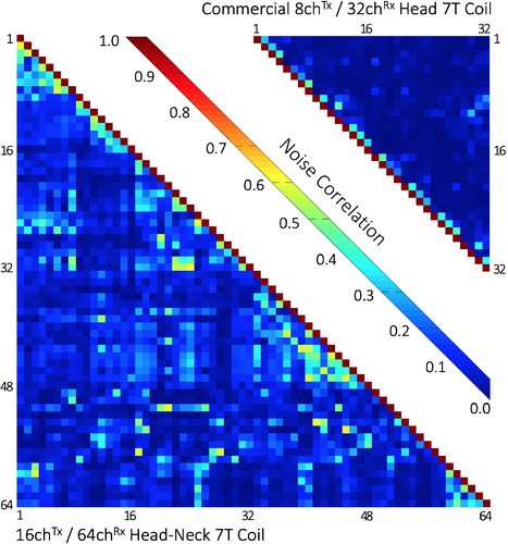
Figure 6 shows the noise correlation coefficient matrices for both the 64-channel Rx elements of the head–neck coil and the 32-channel vendor coil. The 64-channel noise correlation ranged from 0.1% to 58%, with an average of 11.7% for the off-diagonal elements. For the 32-channel, these numbers ranged from 0.08% to 47%, with a mean of 5.1%. Figure 7 shows the unaccelerated SNR map comparisons between the constructed head–neck and vendor coils for the brain, neck, and C-spine regions obtained from an in vivo measurement. In the brain area, the SNR maps show roughly equivalent performance for both coils. In the central brain region, the constructed 64-channel coil showed slightly lower SNR than the 32-channel standard coil by 5%. However, in the face, lower brain stem, and C-spine region, the constructed 64-channel head–neck array outperformed the 32-channel vendor coil by a factor of 1.5, 3.4, and 5.2, respectively.
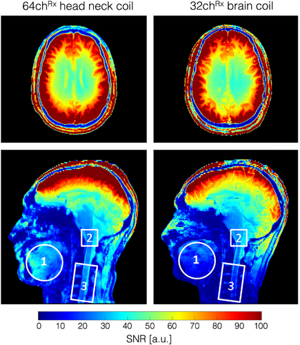
C, cervical.
Figure 8 shows the inverse G-factor maps obtained from representative transversal slices from the brain, lower brainstem, and C-spine for 1D and 2D accelerations. The constructed 64-channel head–neck array shows slightly improved G-factor values in the brain and brain stem areas. However, the 64-channel head–neck coil clearly outperforms the encoding capabilities of the vendor coil at the C-spine region: The constructed coil provides the ability to accelerate at approximately one unit higher at a given noise amplification compared to the 32-channel vendor brain array coil. It should be mentioned, however, that the commercially available brain coil is not suited for imaging the C-spine.

Figure 9 compares the simulated and measured B1+ field maps for the individual Tx channels obtained from the head–neck phantom. Quantitatively, the spatial distributions between simulations and their measurements showed good correlation for each individual channel. Compared to the measurement, the simulation provides about 11% higher B1+ efficiency. Locally, however, the B1+ values differ by up to ±24%. The B1+ field maps of both the CP and CP2+ configurations are shown in Supporting Information Figure S4. The maximum B1+ obtained from the CP mode at the center of the phantom was 96 nT/V in the simulation as compared to 80 nT/V in the measurement. Qualitatively, the CP and CP2+ shim configurations show a good agreement between the measured data and the simulation. On average, the simulation shows an 11% higher B1+ efficiency. Locally, however, the B1+ values differ in a range from ±20%.
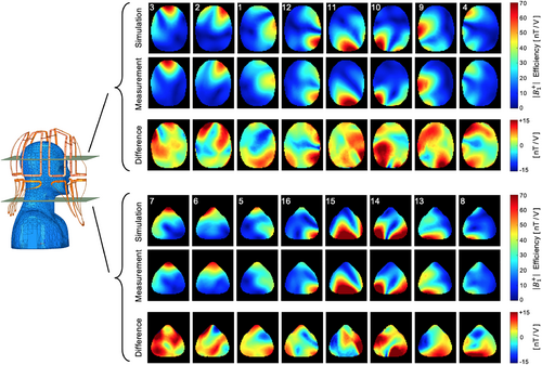
SAR simulations obtained from a multi-compartment human body model are shown in Supporting Information Figure S5. The 10 g-SAR maps were generated with an input power of 1 W for the total simulation. The maximum SAR was determined to be 0.368 W/kg/W.
Initial B1+-shimmed in vivo images showed promising results for large-FOV head–neck imaging studies for clinical settings at 7 T. Figure 10 shows a sagittal image with a region of coverage from the full brain down to the C7 vertebral level with reasonable B1+ shimming.
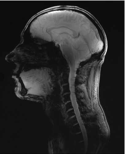
BW, bandwidth; M, matrix.
4 DISCUSSION
In this study, we designed, constructed, and validated a high-density 7 T head–neck coil consisting of 64 Rx and 16Tx coil elements. The coil was optimized to image the brain, brainstem, cerebellum, and C-spine; furthermore, patient comfort and user-friendliness at 7 T was addressed.
The Rx and Tx structures were merged into one housing rather than separating them into a receiver helmet and tubular Tx topology. Accomplishing this, the technical challenges associated with 7 T high-field MRI had to be solved within the highly space-constrained environment.
The array coil performance was evaluated via i) bench-level measurements such as QUL/QL-ratios, tuned-detuned isolation, and neighboring coupling; ii) system-level validations, which included component heating, and Tx B1+ maps; and iii) in vivo performance tests, which were carried out by pixel-wise SNR maps, G-factor maps, and noise correlation.
32-channel and 64-channel brain arrays are well understood for 7 T brain imaging.12, 14, 47, 48 However, when extending the coverage toward the neck and C-spine area, there are additional challenges present in the coil design and construction process. It renders the issue of Tx/Rx coupling and temporal signal stability more difficult and requires design alternations compared to array coils built with separated Rx and Tx structures.
The constructed coil showed slight improvements in both SNR and acceleration compared to the standard 32-channel brain array. As expected, most of the benefit was in the extended coverage when compared to the brain-only coil design. Previous coil hardware studies have shown that using 32 channels improve the quality of simultaneous brain and C-spine imaging at 3 T.49 However, in order to serve the neck/C-spine region with detectors, the number of available elements around the brain has to be substantially reduced to cover the neck/C-spine if the total element count is fixed at 32. This renders brain imaging suboptimal compared to 32-channel brain-only array coils. The customized 64-channel coil used in this hardware study addressed this limitation by providing sufficient coil elements to maintain the element count around the brain and provide new elements for the face, neck, and C-spine region. In our design, 42 coil elements serve the brain region, which yielded a slightly higher loop density compared to the standard 32-channel brain array.
Mounting the Rx and Tx structures on the same coil former shows increased interelement coupling between the Rx and Tx structures. In our first attempt, we incorporated a 15 mm spacing between both structures, which turned out to be insufficient for well-decoupled elements.50 Actively detuned Rx elements showed overall increased coupling between the Tx channels, and this made it difficult to tune and match the Tx elements properly. In our second attempt, we used a 30 mm offset, which isolated both structures sufficiently. However, especially for the larger Rx coil elements at the neck region, an additional passive detuning circuitry was needed at the opposite side of the drive port to fully decouple the element from the Tx structure. This is attributed to the larger Rx elements with only one detuning location still being able to feature a dipole-like behavior, which highly couples into the Tx array. The incorporated second detuning break point helped to prevent this effect.
The coil construction and the safety assessment required an accurate electromagnetic simulation model. The lumped capacitor elements of the 16-channel Tx array were optimized using the co-simulation method.32 The outcome was used to guide the Tx array construction process. For safety validation, it was also necessary to capture the interelement coupling behavior of the 16-channel Tx array in the simulation. This was a critical step to accurately model electromagnetic field quantities observed in the phantom. The bench-measured S-parameters demonstrated good agreement with the simulated results, indicating an overall successful implementation of the simulated guided design process. The adaptability of the RID networks between adjacent Tx elements added an increased degree of freedom for decoupling the Tx array under a loaded condition while maintaining 50 Ω at the drive port. The RID network was also well suited for decoupling adjacent Tx coil elements, which were geometrically separated by the posterior and anterior housing segments. Further decoupling networks of the nearest Tx neighbors were not necessary because a coupling of <−14 dB was achieved by the geometric distance. The Tx array's S-parameters showed only slight to moderate changes under different coil loads, maintaining the required critical tuning and matching condition in subjects of different sizes.
The measured B1+ field maps qualitatively showed a good match between the simulated and measured fields. The differences are likely attributable to the complexity of the overall constructed RF coil system and the inadequacy of capturing all these details in the simulation model. In addition, the B1+ maps were simulated without including the receiving array in the model, which can attenuate the B1+ field overall or modulate it locally.51
In general, the constructed coil showed better overall decoupling values between the elements compared to the simulation, with some larger discrepancies in some cases. This mismatch can compromise the accuracy of the coil's safety assessment. For this reason, a second shim configuration (CP2+) was evaluated. Both shim sets showed a good agreement between simulation and measurement, with local differences of ±20%. However, a 2.5-fold safety factor was added to account for a conservative local SAR estimation.
The mean noise correlation between Rx coil elements was 11.7%. The anterior Rx elements serving the neck area showed the highest noise correlation, with values of up to 58%. These coil elements deliberately have a greater distance from the neck region to allow different body shapes to fit comfortably inside the coil. However, these coil elements are underloaded due to the larger distance to the body, which increases the Q-factor; thus, the coupling between the coil elements increases. In the brain, the receiver sensitivity is comparable with the standard 32-channel head coil. In the central brain region, the constructed head–neck coil showed slightly lower SNR (5%). This is clearly attributed to the overall larger coil size. Key design criteria for the coil were its robust usability for everyday clinical use and to fit larger head-sized subjects when compared to the commercially available 8-channel Tx/32-channel Rx coil array. From the latter implication, the coil size was deliberately chosen to be larger than the commercially available head coil.
Initial large FOV in vivo imaging demonstrated the feasibility of capturing both the brain and C-spine region within one acquisition at 7 T using B1+ shimming from 16 Tx channels and the highly parallel reception of 64 coil elements. In future studies, the constructed 7 T array coil will be used to acquire new informative data of the central nervous system involving the brain and spinal cord. The ability of combined whole brain and C-spine cord imaging to provide more insight into the functional coupling between the brain and spinal cord will be valuable.
5 CONCLUSION
A 64-channel Rx array coil with 16 integrated Tx channels was simulated, constructed, and tested for combined brain and cervical spine imaging at 7 T. We compared the coil to a 32-channel brain-only coil. The highly parallel coil designed in this study is well suited for either brain examinations or head–neck–spine studies. The high SNR of the head–neck Rx coil will likely improve clinical and research studies focused on brain and spinal regions.
ACKNOWLEDGMENTs
We thank Bernd Stoeckel from Siemens Healthineers (Siemens Healthcare GmbH, Erlangen, Germany). for his technical assistance and helpful discussions. This work was supported by the National Institutes of Health [5R01EB006847, 1P41EB030006, 1S10OD023637]; and the Federal Ministry of Education and Research Germany (BMBF) [IN2016-2-226].
CONFLICT OF INTERESTS
Rene Gumbrecht, Ralph Kimmlingen, Markus Adriany, Yulin Chang, Christina Triantafyllou: employees of Siemens Healthineers.
Open Research
DATA AVAILABILITY STATEMENT
Original data are available from the corresponding author upon reasonable request. The data that support findings of this study are openly available in github at https://github.com/keyarray/headneckcoil.52


