Stretchable triboelectric sensor for measurement of the forearm muscles movements and fingers motion for Parkinson's disease assessment and assisting technologies
Abstract
Parkinson's disease (PD) is a degenerative, neurological disease that causes motor dysfunctions on the patient. Currently, the symptoms and progression of the disease are assessed by physicians who diagnose through careful observation, according to the Movement Disorder Society (MDS)-sponsored Revision of the Unified Parkinson's Disease Rating Scale (UPDRS). In this manuscript, we report a portable sensor device based on a flexible Triboelectric Nanogenerator (TENG) formed from a dielectric material with a size of 4 cm × 3.5 cm and an aluminium (Al) electrode with dimensions of 2 mm × 3 mm, to monitor the movement of forearm muscles and tendons. When the hand or fingers extend or flex, the short gap between the dielectric polymer and the small conductor changes, generating a voltage due to triboelectric contact. The device is used to assess localized bradykinesia and rigidity of fingers and hands, as well as wrist and arm tremors. The voltage signal of the proposed sensor shows different waveform shapes, time duration and amplitude for each level of classification from ‘normal’ to ‘moderate’ status, described on the MDS-UPDRS examination of hand movement, finger tapping and pronation–supination movement. Hence, we demonstrated that the proposed sensor can potentially be used for quantification of the symptoms and diagnosing. In addition, single finger motion tracking is also achieved by placing the triboelectric sensor in different positions around the forearm, close to the tendon connected to the finger under test. This way we avoid the placement of the sensor directly on the fingers, improving comfortability and long-term wearability. The presented TENG sensor is fully integrated with the processing and the transmission board exploring new opportunities for triboelectric transducers in small motion detection of muscles. The future aim of this research is to provide real-time monitoring of the disease progression as feedback for personalized treatment of the PD patients.
1 INTRODUCTION
Parkinson's disease (PD) is a progressive, neurological, degenerative disorder that affects one individual in every 1000, leading to impairment in mobility, eventual loss in motor control, and cognitive dysfunctions impacting the well-being of the patient (Williams, 2010). Normally, some of the symptoms that affect the patients suffering from this disease are rest tremor, bradykinesia, dyskinesia, gait abnormalities, rigidity and postural instability (Jankovic, 2013). The proper observation of these symptoms can rank the patient severity as 0: Normal, 1: Slight, 2: Mild, 3: Moderate, 4: Severe, according to the Unified Parkinson's disease Rating Scale (MDS-UPDRS), providing information for the early detection, diagnosis, and treatment of the disease (Goetz et al., 2008). However, Godinho et al. (2016) shows that these symptoms are not commonly supervised by using wearable sensors, since there are few and incomplete commercial technologies available. New internet of things developments have open the path for an increment of remote monitoring platforms based on smart wearable devices, that collect more realistic information of motor and nonmotor symptoms, providing constant and personalized homecare for PD patients (Dorsey et al., 2016). As stated in Espay et al. (2016), the new wearable technologies are replacing traditional assessment methods due to validity, low cost and capability of tracking frequency and amplitude of movements related to PD motor symptoms during day and night. Currently, new systems are proposed to diagnose and quantify the evolution of PD using EMG, blood pressure and inertial sensors such as accelerometers and Gyroscopes that measure angular velocity, frequency, and angle amplitude in different parts of the (Godinho et al., 2016; Jilbab et al., 2017). For instance, Bernad-Elazari et al. (2016) and Phan et al. (2018) intend to quantify overall body rigidity and postural instability using wearable body sensors, to measure motion asymmetry and imbalance issues that can be observed when the patient walks or arises from the chair. Similarly, in Memar et al. (2018), they use sensors to assess whole-body bradykinesia, which is the slowness of motion and its study is required for the diagnosis of Parkinson's disease (Memar et al., 2018). On the other hand, high-frequency rest tremor in limbs also indicates rigidity and is clinically associated with PD as a classical symptom (Obeso et al., 2017). The work in Vivar et al. (2019) classifies the arm tremor in one of the first three levels of the UPDRS scale using IR sensors and cameras but may not be suitable for continuous data acquisition at home. In other traditional systems, tremors can be evaluated as in Kim et al. (2018), which uses wearable gyroscopes to monitor the vibration of the wrist and index finger, employing a convolutional neural network to process the signal. Thus, not only the complete body motion but also hand and fingers movement are used in the classification of the disease. For instance, in Delval et al. (2016) rigidity is observed in finger-tapping, hand-tapping and foot-tapping freezing, becoming bio-markers in the prodromal detection of the disease. Furthermore, an objective analysis of bradykinesia is done by careful observation of motions as pronation/supination, finger tapping, opening–closing and wrist extension (Goetz et al., 2008). Hence, inertial wearable sensors, some of them fixed in gloves, are also placed on arm, hands and wrist to study and classify bradykinesia of the upper limb as in REF (Lin et al., 2018; Rabelo et al., 2017; Spasojević et al., 2017; van den Noort et al., 2017). Unfortunately, for the case of PD assessment, some inertial sensor systems are not based on flexible or stretchable technologies, which affect wearability and continuous monitoring of the devices. In REF (Espay et al., 2016), the wearability assessment method for different PD-monitoring devices concluded that the success of medical devices depends on its portability features, mostly comfortability. Normally, patients stop using wearable devices after 6 months to 1 year, so new options for optimum long-term wearable devices are necessary for patient engagement. Developments as in (Rinieri et al., 2017; Xi et al., 2020) that senses finger and wrist tremors require the placement of the sensor directly in the area under measurement (hand and phalanges), which may be uncomfortable.
Specifically, some works intend to avoid placing the devices on the hand, fingers or the joint under motion, using other methods including electromyography (EMG) for non-direct and non-invasive measurement of tremor, bradykinesia and gait impairments as in Yang et al. (2020). In Yang et al. (2020) instead of directly measuring the angle of the motion of the elbow, an EMG sensor is attached with tape to the biceps muscle to measure the whole elbow flexion (Yang et al., 2020). In Scholten et al. (2016), a sensor to assess finger tapping is placed in the skin on top of the Flexor Digitorium and the Extensor Digitorium Communis muscle on the upper limb.
This opens the possibility to use knowledge of new emerging technologies that intend to track and recognize wrist, hand and finger motion by measuring the forearm muscles' contraction using EMG or small accelerometers to detect the vibration of specific points the arm. The last is feasible because the motion of the phalanges and hand is dominated by the contraction and relaxation of forearms muscles such as the flexor digitoriums, the palmaris longus, the flexor, pollici longus and the flexor carpi ulnaris, which are relevant for hand and wrist function (Janda, 1983; Roman-Liu & Bartuzi, 2013). The systems in Li et al. (2015) and Zhang, Chen, et al. (2018), for example, use different EMG sensors placed in different points surrounding the forearm for accurate gesture recognition and the capture of the fingertip force. On the other hand, small accelerometers as in (Yu et al., 2010) and force-sensitive resistive sensors as in (Li et al., 2012), are wrapped around the arm to classify the finger motion through the analysis of the vibration and the pressure distribution of the skin on top of the muscles associated with phalange dynamics. Yet, drawbacks still exist for the sensors that measure muscle bioelectricity, since this value depends on fat and tissue properties (Yu et al., 2010). In addition, such transducer topologies are still not completely flexible or stretchable for long-term wearability. At this point, triboelectric nanogenerators (TENGs) can become a solution for PD monitoring and diagnosing since they have the potential of solving all the wearability issues due to its features as harvesters and stretchable sensors (Zhang, Han, et al., 2018). TENGs working principle depends on the triboelectric interaction between two dielectric materials (generally stretchable polymers), which generates a voltage signal depending due to the contact and separation and the insulating layers (Wang et al., 2016). These new sensors have been implemented as body motion sensors, for the tracking of the bending angle of different human joints and respiration detection (Ma et al., 2018; Yi et al., 2015). Particularly, TENGs have been also demonstrated as flexible self-powered motion transducers, designed in multiple arrangements and topologies as in (Dhakar et al., 2016; Shi et al., 2016) and where the triboelectricity between the skin and polydimethylsiloxane (PDMS) or between PDMS and a liquid is used for finger motion and pressure detection and bending angle differentiation. Other examples are observed in (Wang et al., 2018) and (He et al., 2019) where stretchable sensors are integrated into a hand glove, designed to acquire finger bending and motion information. Moreover, the monitoring of small muscle movements has been achieved using TENG and presented in the literature as in (Lin et al., 2017; Ouyang et al., 2017; Vera Anaya et al., 2020; Zheng et al., 2016) where the contraction and relaxation of cardiac and eye muscles drives an electrical signal on the nanogenerators directly placed on them. Even though this technology is versatile, flexible, portable and sensitive to small muscle motions, the sensor must be located directly on the joint under measurement. To the best of our knowledge, in the state of the art, the only development found that intents to indirectly assess finger and hand motion by wrapping a TENG transducer on the forearm is presented in (Chowdhury et al., 2020). Thus, having in mind the previous applications related with forearm, hand and finger motion sensing, it is natural to think that flexible TENG can be exploited not only as gesture sensors but also in other medical applications related with involuntary motions, as the diagnosis and assessment of Parkinson's disease (PD).
Consequently, in this manuscript, we report a new flexible triboelectric transducer integrated into a portable electronic system with wireless data transmission that can be used as an assistive technology for PD assessment. The device is placed in the forearm on top of the skin above the Digitorium and Palmaris muscles and associated tendons, which contracts and relaxes depending on the dynamic of phalanges and wrist. Hence, initial experiments emulating local bradykinesia, rigidity and tremor based on the MDRS-UPDRS scale were performed. The analysis of the sensor output due to specific movements as pronation/supination, finger tapping, hand opening–closing and wrist and arm tremor demonstrates the potential of the device for the diagnosis and evaluation of the progress of PD. Finally, in this work the proposed sensor also detects and recognizes the motion of specific fingers when the device is placed in different spots around the forearm.
2 MATERIALS AND METHODS
2.1 Fabrication of Ecoflex™
The polymer triboelectric layer is fabricated with a 1:1 mixture of components A and B of commercial Ecoflex™ 00-30 from Smooth-On as described in Zou et al. (2019). After 5 h in ambient temperature, the material is retired from the mould and cut in the dimensions described in Section 3.1.
2.2 Fabrication of the printed circuit board
The board is designed in the licensed software Altium and fabricated with a commercial manufacturer. All the components except the Battery are Surface Mounted Devices (SMD) to achieve a small size. The BLE board is an MDBT50Q module from Raytac Corporation, based on the NRF52840 Bluetooth chip from Nordic Electronics. The small lithium-ion battery is attached with Isolating tape to the PCB. Finally, the Ecoflex™ and Al layers are attached to the sensor as graphically explained in Figure S2. In Figure S4, the signal is received by the Sparkfun Pro nRF52840 commercial board which sends the data to a Python code for posterior visualization and storage.
3 RESULTS AND DISCUSSION
3.1 Triboelectric-based forearm motion sensor integrated into a PCB: Design and characterization
As illustrated in Figure 1a, the sensor system is assembled by attaching a thin, flexible layer of Ecoflex™ to a small printed circuit board (PCB), which is in charge of the signal processing and transmission, and possesses a small electrode made with aluminium tape. The Ecoflex™ layer is attached to the PCB through two small rectangles of Polyurethane (PU) Foam that allow a separation space between the Ecoflex™ and the Al electrode. The dimensions of the PCB, the Ecoflex™ layer and the Al electrode are 3.5 cm × 4 cm, 4 cm × 1.4 cm × 1.5 mm, and 5 mm × 3 mm, respectively (Figure S1 shows a clearer assembly process of the sensor).
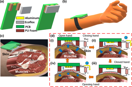
The sensor is attached to the forearm on top of the flexor muscles/Tendons community (Figure 1b,c). As observed in Figure 1c, the sensor is located on top of the skin above the muscles or their inserted tendons such as the flexor carpi radialis (FCR), the flexor digitorium superficialis (FDS), flexor digitorium profundus (FDP), the palmaris longus (PL) and the flexor pollicis longus (FPL) which together are in charge of moving and bending the fingers (proximal, intermediate and distal Phalanges), and the wrist. When the hand is opened or closed, the muscles and tendons contract or relax accordingly. The sensor also could be placed on top of the community of tendons connected to such muscles. In both cases, the contraction or relaxation changes the volume of the muscles and the skin on top of them also changes. As observed in Figure 1di, when the hand opens, the volume on the skin seems to expand the tissue making the Ecoflex™ layer moves towards the AL electrode on the PCB (Clear view in Figure S2). When the polymer and the conductor make contact, the triboelectric effect allows positive charge transfer from the dielectric to the conductor as described in the triboelectric series (Lee, no date). When the hand starts closing, the volume of the forearm reduces and the skin and the muscles go back to their initial positions, moving the Ecoflex™ (negatively charged) away from the AL (Figure 1dii) until it reaches the maximum separation (Figure 1diii). Due to the distance, the positively charged Al attracts negative charges from the ground reference through the resistive load. The last, results in current and voltage generation, in this case, positive according to the sign convention on Figure 1d transfer negatively and positively according to the triboelectric series (Lee, no date). Posteriorly, when the hand opens again, the negative Ecoflex™ moves closer to the AL conductor, pushing the negative charges on the electrode back to the ground reference and resulting in an opposite voltage. When the motion dynamics of the fingers, hand or wrist are periodic, the voltage signal behaves the same. Furthermore, the characteristic of the electric output also depends on the movement amplitude and speed of the forearm's skin and muscles that control the hand and the phalanges.
Additionally, as observed from Figure S2, the maximum gap of the sensor varies approximately from 2 mm to 0 mm. Besides, the area of the Ecoflex™ is also small, and the area of the Al electrode is even smaller. For such reason, The PCB has a processing circuit equal to the one used in the past in (Vera Anaya et al., 2020) for the sensing of the small contraction–relaxation motion of the orbicularis oculi muscle surrounding the eye. The circuit serves as a high impedance load for the sensor, amplifies the voltage signal and fixes a DC offset of 1 volt with a maximum amplitude swing from 0 V to 3.3 V (Figure S3). The signal is later digitalized by the Analog-to-Digital Converter (ADC) of one of the input channels of the BLE module NRF5832 from Nordic Electronics which transmits the data wirelessly to a computer (Figure S4).
3.2 Hand, arm and fingers movement examination for preliminary assessment of localized Bradykinesia and Rigidity for Parkinson's disease
3.2.1 Hand and pronation–Supination Movement Examination
According to the MDS-UPDRS rating scale for diagnosing Parkinson's disease, physicians must test specific body motor characteristics to determine the grade of dementia of the patient. The output can be classified with 0 (Normal), 1 (Slight), 2 (Mild), 3 (Moderate) and 4 (Severe). Some physical tests to assess localized bradykinesia (slowness of movement) or rigidity due to PD closely evaluate the hand and arm motion characteristics. In Figure 2a, it shows the voltage output of three different severity levels of PD observed in the hand opening/closing motion, classified using the MDS-UPDRS scale. For this initial experiment, the hand motion was emulated by the user under test, simulating the specific amplitude and time characteristics of each classification level in exercise 3.6 of the MDS-UPDRS manuscript, related to ‘Hands Movement Examination’. In this assessment, the user is required to open and close the fist approximately 10 times (Figure 2ai). Figure 2aii presents the output when no PD problem is simulated (level 0). The signal has a DC offset in 1 V and is negative (lower than 1 V) when the hands close and positive (Higher than 1 V) when the hand opens. Having in mind that the amplifier in Figure S3 in the supplementary information has negative gain, the waveform in Figure 2aii shows coherence with the theory explained in Section 3.1. When the hand opens the sensor voltage is negative and changes sign when the signal is passed through the negative gain amplifier, being positive at the output and similarly happens when the hand closes. Furthermore, there are 9 clean and recognizable cycles with the maximum amplitude allowed by the ADC of the BLE (0 V–3.3 V). In contrast, in Figure 2aiii, a slight (level 1) slowing of the fist opening and closing is emulated. The waveform characteristic shows a negative peak followed by a positive peak for closing fist and a positive peak followed by a negative peak for opening fist. Evidently, the cycle duration now increases and the fluctuation of the signal may probably be due to the non-uniform muscles of the muscles and the skin more notorious in this slow movement. On the other hand, the amplitude of the signal did not change, since the opening and closing amplitude was not changed. Differently, Figure 2aiv presents a difference in the duration of the opening–closing cycle and a decaying amplitude which is the product of the mimic performed by the user emulating moderate symptoms (level 3). As expressed on the MDS-UPDRS manuscript, a PD patient in level 3 stops or reduces the amplitude of the movement in a short time after starting the exercise. The waveform clearly shows such behaviour, demonstrating the potential of the sensor to be used for the quantization of the symptoms in this test. The physical demonstration of the outputs in Figure 2 can be observed in Video S1.
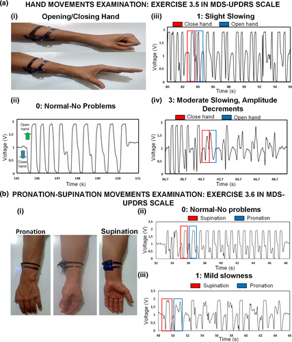
In Figure 2b, it also presented the result for exercise 3.6 in the MDS-UPDRS scale related to the ‘Pronation–Supination Movement Examination’, which is an important indicator for PD diagnosing. For this test, the user is asked to perform up to 10 pronation–supination movements of the forearm (Figure 2bi, Video S2). Once again, the user emulates the action based on the different severity levels. Figure 2bii portraits the output when the person performs the action naturally without any problem (Level 0). The supinating action generates a negative voltage (<1 v in this case) followed by a positive voltage. The pronation action also generates a similar voltage, with a high amplitude, probably higher than 3.3 V, explaining why the signal looks clipped or saturated at the peaks. Besides, the signal looks clean and consistent for different cycles. In contrast, in Figure 2biii is the waveform that results when the user emulates actions with mild slowing without decreasing the amplitude of the motion. The time for each cycle is longer now, and there is a difference between both actions, with a longer time for the supination as well as a more distorted signal shape than the pronation. The amplitude is practically unchanged because the user was asked to keep the same as in the test in Figure 2bii. Finally, in Figure 2 is evident the high power of the signal compared with the inherent electric noise, which is due to the electronic filtering in the PCB.
3.2.2 Finger Tapping Examination
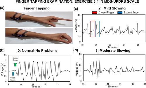
Another experiment is performed to assess exercise 3.4 on the scale related to the ‘Finger Tapping Examination’. The user is required no to tap the index finger with the thumb as in Figure 3a up to 10 times. In Figure 3 and Video S3, the output from finger tapping is also portrayed for different levels of rigidity/slowness. Figure 3b presents the signal when the user taps the finger without emulating any bradykinesia problem. When the finger extends, the signal is above 1 V (considered negative for explanation purposes), and when the finger taps, the signal is negative or below 1 V, coherent with the results for opening and closing hand. Nonetheless, the voltage amplitude is lower than the one obtained in Figure 2. This is expected since now just one finger is moving instead of the whole fist. The thumb, in this case, is in the same position so the action of the FPL muscle is less compared when the whole fist closes. A similar rational inference can be done with the rest of the forearm muscles and tendons that may have less influence in the motion of one individual finger. A mild slowing with lower motion amplitude of finger tapping (Level 2) results in the waveform in Figure 3c. The cycle duration increases due to the user slowing the motion on purpose, but there are particular characteristics in the amplitude. When the finger closes, the amplitude is less negative compared with Figure 3b. In some cycles, the amplitude when the finger taps is also lower than the one obtained when no rigidity problems, but it may be due to involuntary inconsistent tapping amplitude from the user under test. Finally, the user was also asked to emulate moderate symptoms (level 3) whose result is presented in Figure 3c. As observed, the amplitude decreases soon after starting the tapping action, which is contemplated in the description of a moderate level. Hence, the results also demonstrate the positive potential of the sensor in the assessment of the localized symptoms due to finger kinetics.
3.3 Tremor vibration assessment
Tremor is another important symptom in patients with Parkinson's disease. Its assessment is contemplated on exercises 3.15–3.17 of the MDS-UPDRS scale which evaluates postural, kinetic and rest tremor. The physician must observe these symptoms during all the evaluation process of the patient and annotate the estimated amplitude of the tremor. In Figure 4a, the user under test is asked to vibrate with different amplitudes the entire forearm separated from the body while keeping the wrist and hand static, to emulate a similar movement to postural tremor. The individual moves the arm with a low amplitude tremor until reaching a high amplitude tremor of about 5 cm. In Figure 4aii, it is observed how the peak voltage amplitude increases and then continuously decreases when the forearm vibration is stopped. According to this result, the amplitude is directly dependent on the tremor amplitude and if further characterization is performed, a more accurate model can be used to associate the amplitude of the signal with the physical amplitude of the tremor.
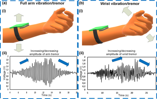
Posteriorly, the person under test is also asked to just vibrate the wrist keeping the forearm straight, starting from a low amplitude vibration to a greater amplitude vibration as in the first experiment (Figure 4bi). The outcome of this experiment in Figure 4bii shows also a signal that increases related to the vibration amplitude and then stops. Although the behaviour of the two vibration waveform is similar, the vibration from the wrist generates lower voltage than the vibration of the forearm. Thus, the preliminary experiment in Figure 4 and Video S4 exhibits a direct association between the voltage and the amplitude, and more research and more testing should be done on actual patients to understand more characteristics of the tremor and rate the vibration according to the main PD severity scale.
3.4 Output of the forearm TENG-based sensor due to different moving fingers
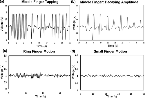
As noticed in Figure 3, the assembled sensor is sensible to finger motion. In the specific case of Parkinson's disease assessment, the finger under testing must be the index. However, such an experiment can also be done for the rest of the fingers (Video S5). In Figure 5a, the waveform corresponding to a fast and slow taping motion of the middle finger is presented. In this case, the output is even greater than the result for the index finger in Figure 3. Besides, Figure 5b shows the output when the middle finger is moved with a decaying amplitude, showing a direct relationship between the motion and the voltage. When the same test is repeated in Figure 5c using the third finger (ring finger), the signal amplitude is smaller (but not neglectable), in comparison with the result obtained with the index and middle finger. Something similar happens in Figure 5d, where the output due to the taping of the small finger is weak compared with the rest of the fingers. Interestingly, the results here indicate the dependency of the output due to the motion of a specific finger, proof that the placement of the sensor in the forearm influences the detection of the phalanges. Each of them is connected to each muscle through a tendon, and each specific tendon under contraction changes the shape of the moving skin. Thus, the skin which does not deform equally in all parts affects the movement of the flexible polymeric layer towards the AL electrode. Therefore, in Section 3.5, we study the signal resulting due to different placements of the sensor on the forearm, where specific motion is more sensitive to certain finger movements.
3.5 Output due to different finger motions for specific sensor positions on top of the forearm flexor muscles and tendons
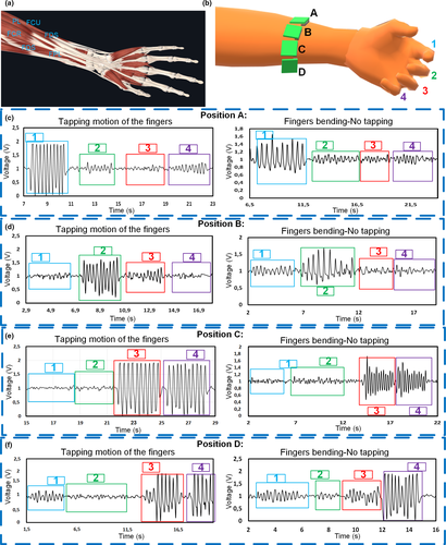
The results in Section 3.4 indicated that when measuring the forearm muscle dynamic for PD assessments the signal output due to each finger is influenced depending on the placement of the sensor on top of the forearm. As observed in Figure 6a, the muscles that control the finger flexion like the FDS or FDP are connected to four tendons to a specific phalange. In literature, for example the measurement and recognition of finger motions are done by using either EMG sensors or Inertial sensors (Li et al., 2015; Yu et al., 2010). Accelerometers as in (Yu et al., 2010) use the skin stretching due to the motion of muscles and tendons to achieve recognition of the fingers. However, in this report, we can achieve recognition of the fingers implementing the designed sensor. As in Figure 6b, the sensor can be placed closer to each of the tendons to aim single finger monitoring. When the muscle and tendon contracts to allow flexion of the finger, the skin close to such tendon also changes in volume, and the triboelectric sensor on top generates voltage due to such small motion (See Video S6). For instance, when the sensor is placed in position A, closer to the tendon that controls the index finger, the tapping motion of such a digit generates a greater voltage than the motion from the tapping of other fingers (Figure 6ci). We can observe in the same figure (Figure 6cii), how different is the signal value when the finger is taped against the thumb, and when the finger is just bent back and forth without tapping, with lower amplitude. In this position, the other fingers also generate a small signal, but not comparable to the values obtained from the index. When the sensor is placed in position B in Figure 6b, it is evident that the motion of the middle finger generates a higher peak value than the motion of the other fingers as illustrated in Figure 6di. The tapping motion also generates a higher signal than the no tapping motion (Figure 6dii). Differently, when the sensor is placed in position C in Figure 6b the signal coming from the motion of the ring and the small finger is quite similar, for taping and no taping motion (Figure 6e). This may be because, as portrayed in Figure 6a, both tendons are very close to each other and the triboelectric sensor is not small enough to detect the individual motion. Finally, we can observe that the result when the location is position D (Figure 6f), only the small finger contributes to a significant voltage output when moved, compared with the outcome of other fingers. In this case, the thumb alone is not evaluated because is mostly controlled by the FPL muscle which is below the FDS and the FDP, which are the main muscles and tendon communities under evaluation in this case.
3.6 Other applications for finger motion monitoring: Hand activity monitoring when using keyboard and finger bending sensing
Finally, some applications related to finger kinetics recognition were tested and graphically summarized in Figure 7 to demonstrate more features of the developed triboelectric sensor for forearm muscles/tendons monitoring. With the sensor, it is possible to track the activity of the hand. For instance, in Figure 7a and Video S7, it is presented the output signal when the person is typing on the keyboard. It differentiated the moments when the person uses the right hand and the left hand, which has the sensor. This can be helpful in activity and productivity monitoring to indicate when the person should stop typing and start resting. This will be important in the future of ergonomic and health fields to avoid the symptoms of certain upper-limb problems due to repetitive movements or bad hand posture, such as Carpal Tunnel Syndrome (Thurston, 2013).
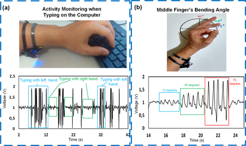
Finally, the other experiment is related to finger bending monitoring (Figure 7b, Video S8). Multiple finger bending measurement systems based on TENG have been achieved before as the one proposed in (He et al., 2019). However, those devices require to be attached to each finger to sense the bending angle. In contrast, in this project, we used the designed forearm TENG to track finger bending. Figure 7b presents the result when the middle finger is bent 15, 45 and 75 degrees. The bending angle is directly related to the voltage peak value, being more evident in the positive peak (above 1 V for this manuscript) which corresponds to the finger closing action. Similar to Figure 3 finger extension generates a lower voltage absolute value than the finger contraction, which is the resulting peak after the triboelectric contact. Finally, the last designed sensor topology improves the portability and comfortability for long-term use if continuous finger bending monitoring is needed in the future, leaving the hands and finger free from any wearable transducer. The result also indicates that the proposed topology can be used for the development of future human–machine interfaces controlled by human muscles.
4 CONCLUSION
A portable TENG-based sensor for forearm muscles/tendons motion measurement for PD assessment and monitoring has been presented. The unique triboelectric sensor is completely integrated into the PCB board working as one complete transducer system. Hand and finger motion is monitored by measuring the kinetic of the muscles of the forearm that control phalange and wrist dynamics. Then, different severity levels of localized Bradykinesia and rigidity symptoms have been emulated with specific hand, finger and pronation /supination motion patterns and were successfully differentiated due to their particular voltage waveform characteristics, generated by the new portable electronic transducer. Increasing and decreasing arm and wrist tremor was emulated by the user under test and evaluated with the device. A direct visual relation between tremor and voltage peak was found, but more research and tests are required for more exact quantification of tremor in the future. The measurement of such small muscle and tendon movements with evident low noise compared with the signal was possible due to the implementation of a conditioning circuit with filtering and amplification stages integrated into the PCB. In addition, the same sensor has also been used to recognize the tapping and bending action of specific fingers, by measuring the displacement of the skin on top of the forearm flexor muscles and tendons associated with each finger. The assembled device performed well in other implementations intended to examine hand activity and finger bending monitoring, with relative success. For future research, the implementation of the proposed PD monitoring systems shall be done in real patients to estimate accuracy and reliability for long-term use in the health field. The energy harvesting features of the TENG may be integrated to achieve energy generation and simultaneous monitoring from small muscle movements.
ACKNOWLEDGMENTS
This work was supported by the Australian Research Council Future Fellowships Grant (FT130100430).
Conflict of interest
No conflict of interest has been declared by the author(s).


