Experimental characterization and finite element modelling of a thermoplastic composite lamina subjected to large shear deformation
Abstract
In this work, the behaviour of a woven lamina for thermoplastic composite material is experimentally and numerically investigated. A thermoplastic composite made of hot-pressed polypropylene (PP) woven laminas is the object of the study. The laminas are composed by tapes that are made up of coextruded core and skins. Experimental tests were carried out to determine the properties of the lamina. The experimental data are used to develop numerical models for the simulation of the experimental test. Three modelling techniques are proposed: The first one implements a macro-mechanical material model, the second one uses a meso-mechanical approach, and the third one discretizes the geometry at the yarn level. The global response of the meso-mechanical material model showed the best agreement with the experimental test, even if it does not represent the optimal solution from the computational cost point of view.
1 INTRODUCTION
Weight reduction in automotive field is one of the most important criteria for the design. In the last decade, the introduction of rigid safety standards was followed by an increase of the vehicle weight. This led to the development of lightweight materials in the design phase of the vehicle structural components. The advantages of thermoplastic materials and their application in the automotive industry were studied by many researchers1-3 in order to meet the increasingly restrictive European directives4 in terms of recyclability and polluting emissions.
Because of the peculiar mechanical properties and failure mode of the thermoplastic materials, their numerical simulation is still an open point.5 In this work, starting from experimental data, a multi-scale approach is implemented in order to simulate the behaviour of a polypropylene (PP) woven lamina used for the production of a thermoplastic composite material.
Woven fabric can be addressed to a multi-scale problem. Three hierarchical levels can be defined6: macro-level, meso-level, and micro-level. Depending on the discretization level, different modelling approaches and homogenization techniques need to be implemented. The fabric at the macro-level can be simulated as a continuous anisotropic material with orthogonal or nonorthogonal axes.7 The yarn reorientation during large deformation can be predicted by a stress and strain transformation from the global orthogonal to the local nonorthogonal coordinate system.8 At the meso-level, the yarns are modelled, and their properties directly influence the characteristic of the whole fabric. The fabric unit cell can be represented as a truss of elastic beams connected by hinges with rotational stiffness.9
In this overview, the goal of this work is to set-up a reliable and computationally cost-effective numerical model of a thermoplastic lamina. Starting with an experimental campaign, the material parameters obtained with the experimental tests were used as input data for the numerical model. In order to find a trade-off between the model reliability and its time-efficiency, the geometry of the model was reproduced with both continuum and discrete techniques. To this aim, the finite element code LS-Dyna is used in its explicit formulation. The numerical and experimental results are then compared and discussed to study the accuracy of the numerical models.
2 EXPERIMENTAL TESTS
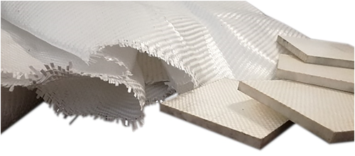
The thermoplastic material named PURE is studied in this work. It is composed by hot-pressed and hot-compacted balanced fabric made of woven thermoplastic tapes (Figure 1). Each thermoplastic tape is made of a highly oriented PP core (homopolymer) and two PP skins (copolymer). The tapes are obtained through a coextrusion process. The production process of PURE is patented.
The mechanical properties of the PURE sheets were largely investigated by Boria et al,10, 11 showing a high strength and stiffness together with a failure mode dominated by delamination. However, for the purpose of this work, the mechanical properties of the meso-components of the composite are experimentally investigated in order to define the constitutive properties of the woven lamina.
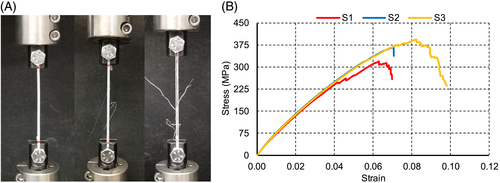
Tensile tests on the single tape were executed to evaluate the Young modulus of the material. A gauge length of 70 mm and a speed of 2 mm/min were adopted. Three specimens were tested: The obtained stress vs strain curve showed a repeatable trend (Figure 2B). The delamination of the external skin (copolymer) caused a smooth drop of the elastic modulus, till the failure of the core (Figure 2A).
The Poisson modulus of the fabric was evaluated testing a fabric specimen in tension. The tensile test was carried out according to the ASTM 5035 standard. The specimens had a width of 50 mm, and each side was ravelled.
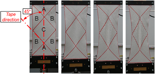
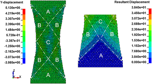
The shear properties of the fabric were evaluated according to the bias-extension test.12-14 The specimens had an aspect ratio higher than 2, and they were tested in extension. The warp and weft tapes were oriented at 45° with respect to the load direction. According to these conditions, three different shear zones15 can be distinguished (Figure 3): no shear region (A), pure shear region (C), half of the shear in the region C (B).16 The behaviour of the C region can be addressed to a trellis mechanism. Therefore, this region is used to define the shear properties of the material. Because of the application of a tensile force on the specimen, the tapes, originally oriented at 45°, started to rotate. The friction between the tapes then produced an increase of the load. The load further raised up as soon as the tapes started to compact. In the last phase of the test, the tapes were subjected to tensile load since they were oriented almost perpendicularly to the load direction.
 ()
() ()
()
where L is the length of the specimen, W is its width, and d is the actual extension of the specimen during the test.
Figure 4B shows the trend of the normalized shear stress vs the shear angle. The normalized shear stress is obtained dividing the normalized shear force by the thickness of the specimen.18 A sharp increase in the shear stress is evident around 0.10 rad of the shear angle. This sudden change of the slope is due to the yarn locking effects. Yarn locking effects starts at a certain yarn angle, that is called locking angle. Here, the yarns further compact and compress each other, leading to a sudden load increase.15 Three different changes of slope can be distinguished. For each slope, a different shear modulus can be defined. The slope S1 corresponds to the reorientation region. The slope S2 represents the after-locking effects of the yarn. The slope S3 corresponds to the region in which the yarns are subjected to tensile load.
3 FEM SIMULATIONS
Three different numerical models were developed to simulate the nonlinear and nonisotropic behaviour of the fabric subjected to the bias-extension test. The material parameters of the finite element method (FEM) models were defined with the results of the experimental tests (Table 1).
| Calculated Parameter | Value | Test Type |
|---|---|---|
| Poisson modulus | 0.42 | Fabric tensile test |
| Young modulus | 5400 MPa | Single tape test |
| Ultimate stress | 380 MPa | Single tape test |
| Shear modulus (S1) | 0.2 MPa | Bias-extension test |
| Shear modulus (S2) | 1.7 MPa | Bias-extension test |
| Shear modulus (S3) | 4.1 MPa | Bias-extension test |
In the first FE model, the fabric geometry was considered as a continuum. The model dimensions reproduced the ones of the specimen used for the experimental tests. The specimen was modelled with four nodes Belytschko-Tsay shell elements with a mesh size of 5 mm. The upper and lower extremity nodes of the specimen were constrained to reply the same boundary conditions of the experimental test. The planar-orthotropic material model MAT_FABRIC (MAT_34) was adopted. This material card models the fabric at macroscopic level, using the Hooke law as the constitutive equation.19 Moreover, the use of the Green-Lagrange strain formulation ensured the material axes to be orthogonal. This material model demonstrated a high sensitiveness to the characteristic of the elastic liner. This parameter of the material card, when activated, reduces the tendency of the central elements (C region of the specimen) to undergo to excessive wrinkle. Accordingly, the characteristics of this parameter were tuned with trial and error procedure. Figure 5 shows the force-stroke curve obtained with the MAT_FABRIC in comparison with the experimental result. The load at maximum displacement is quite well predicted by the numerical model, even if the trend of the numerical curve presents an opposite concavity. This first FE model needed lower time for the set-up and the simulation; therefore, it was desirable from a computational point of view.19 However, it ignored the interaction between the yarns, neglecting the reorientation effects and their influence on the global response of the fabric observed during the experimental bias-extension test.
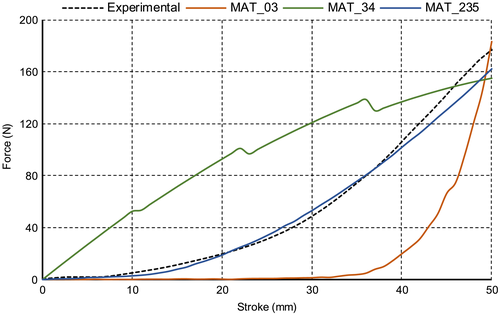
In the second FE model, the MAT_MICROMECHANICS_DRY_FABRIC (MAT_235) material model is used. The specimen dimensions, boundary conditions, and element type were the same of the previous model, whereas a mesh size of 10 mm was adopted for this model. The adopted material model considers the geometry of the fabric as a continuum too, although its material formulation accounts for the yarns meso-mechanical interaction, ensuring a higher degree of detail compared with the material card used in the first FE model. The MAT_MICROMECHANICS_DRY_FABRIC was developed by Tabei and Ivanov,20 and it can simulate the interactions between the yarns as a trellis mechanism. In the material card, a yarn's locking angle can be defined. Beyond this threshold-angle, the yarn-locking effects, explained in Section 2, become more evident. The FE model was made up of a basic structure repeated many times. The basic structure is defined as the representative volume cell (RVC). This cell is the constitutive periodic structure of a woven fabric material. Each RVC is divided in four different sub-cell, and each sub-cell defines the fundamental characteristic of the yarn. The force-stroke curve obtained with the MAT_MICROMECHANICS_DRY_FABRIC is shown in Figure 5. It is possible to notice that the experimental trend is well captured by the numerical curve. In the input parameters, the same value for the Young modulus in the weft and warp direction was adopted. Several simulation attempts were run to calibrate the discount factor μ. This is a nonphysical parameter that scales down the yarns shear resistance before the reaching of the yarns locking angle.15 The value of this parameter demonstrated a strong influence on the simulation result. The tolerance angle for locking demonstrated also to have relevant effects on the force trend of the FE model. The tolerance angle smooths the transition force between the unlocked and the locked yarns condition. It was calibrated with an iterative process taking as reference the experimental curve.
In the third model, the geometry of each single tape of the fabric was modelled. Therefore, the specimen was discretized at the yarn level. The interactions between the warp and the weft yarns were modelled with a penalty-based contact algorithm. Each yarn was meshed with 2 mm four nodes Belytschko-Tsai shell element. The isotropic plastic material model MAT_PLASTIC_KINEMATIC (MAT_03) was used. It was possible to use a material card with a low number of parameters because the interactions between the tapes and the orthotropy of the model are considered discretizing the geometry. The force-stroke curve obtained with this third FE model is shown in Figure 5. The load starts to rise significantly at 30 mm of stroke, where the locking effects become more consistent. The load at the maximum displacement is in good agreement with the experimental evidence, although the reorientation regions are quite different. This is the reason why the two curves have a similar trend but with different values of load for the intermediate strokes. This important difference is due to the low shear stiffness of the FE model. Indeed, because of the texture of the fabric, the yarns are free to slide and rotate about the axis perpendicular to the fabric plane. This effect can be slightly reduced by increasing the friction coefficient between the yarns.
In Figure 6A, an out of plane deformation in the central part of the numerical specimen can be noticed. This deformation can be also observed in the experimental tests. The Figure 6B confirms the hypothesis of the null displacement in the A region of the specimen.
4 CONCLUSION
A composite woven lamina used for the production of a thermoplastic composite made entirely of PP was the object of this study. Experimental tests were performed to evaluate the material's constitutive properties. The large shear deformation of the fabric is the focus of the work. In this type of deformation, the yarn reorientation and the locking-effects have a strong influence on the global behaviour of the material. A recursive algorithm based on geometrical assumptions was first implemented to extrapolate the shear properties of the fabric starting from the experimental results of the bias-extension test. The bias-extension test was then simulated using different approaches and material models, with the numerical finite element code LS-Dyna. Three different FE models were evaluated. The material model MAT_MICROMECHANICS_DRY_FABRIC resulted the most suited to capture the load-displacement trend of the experimental bias-extension test. The meso-mechanics formulation proposed by that material model allows to account for the yarn mechanics during the deformation. However, the calibration of this material model is more time-demanding due to the high number of input parameters required. A second model, based on the material model MAT_FABRIC was developed. Even if the MAT_FABRIC demonstrated less accuracy of the results in comparison with the experimental evidence, its lower number of parameters and the lower computational cost make this material model suited for the simulation of large-scale components. The last FE model examined in this work took also into consideration the real texture of the fabric. Each single yarn of the fabric was modelled, and the yarn mechanics and reorientation effects were accounted by the discretization of the geometry. The deformation field found in the experimental bias-extension test was accurately simulated with this last FE model. However, this last FE model requires proper contact formulations in order to avoid low shear resistance between the yarns. The difference in the shear resistance between the yarns was the reason of the important discrepancy evidenced in the global force-displacement trend between the experimental and the numerical results. The information got in this work gives an important base for the simulation of components made of thermoplastic composites.


