Thin patient-specific clavicle fracture fixation plates can mechanically outperform commercial plates: An in silico approach
Abstract
Current fixation plates used to operatively stabilize clavicular fractures are suboptimal, leading to reoperation rates up to 53%. Plate irritation, which can be caused by a poor geometric fit and plate thickness, has been found to be an important factor for reoperation. Moreover, muscle attachment sites (MAS) have to be detached occasionally. To improve current surgical clavicle fracture treatment with plate osteosynthesis, a change in plate design is required. The goal of this study was to design a patient-specific clavicle fracture fixation plate that includes geometrical optimization and stiffness determination. Its biomechanical performance has been compared with a commercial plate by examining the geometric fit, anatomical outline, stresses and interfragmentary motion using a finite element analysis with physiological loading and boundary conditions. Evaluation showed a better geometrical fit of the patient-specific plate as well as an improved fracture reduction. Displacements between fracture fragments were lower in case of the patient-specific plate, both when a fracture gap and no fracture gap were present. Results indicate a superior mechanical performance in terms of all investigated outcomes of the patient-specific plate compared to the commercial plate, while better aligning with the patient-specific geometry and without the need for MAS release. Due to the patient-specific geometry and reduced thickness, these fixation plates are expected to decrease the operation time, as intraoperative contouring will become irrelevant, and to decrease reoperation rates as implant irritation will be minimized.
1 INTRODUCTION
Clavicle fractures are common injuries, representing 2.6%–4% of all fractures.1 Current evidence shows that the number of surgically treated clavicular fractures has increased by 190% over the last decade.2 Fixation plates currently used to operatively stabilize the fracture are however suboptimal, leading to reoperation rates up to 53%.3 Plate irritation, caused by a poor geometric fit and plate thickness, has been found to be an important reason for reoperation.4
Indeed, several studies previously reported a poor geometric fit of the current fixation plates.5, 6 Additionally, these plates interfere with soft tissues7 due to the high variability of the clavicle shape8, 9 and its muscle attachment sites (MAS).10 To overcome these issues, intraoperative bending of the plate is often required to achieve an appropriate fit. Nevertheless, part of the MAS sometimes still has to be detached.7
To improve current surgical clavicle fracture treatment with plate osteosynthesis, a change in the plate design is needed. Improving the current clavicle fracture fixation would require the following two steps: First, the design process should take into account the clavicle morphology such that a better geometric fit is achieved and that overlap with muscle attachment sites is avoided.7 The additional benefit is that geometrically optimized plates can act as a template to facilitate fracture reduction. Secondly, the plate thickness should be optimized with minimal thickness to reduce plate irritation4 while still providing sufficient stability to allow fracture healing.
Indeed, biomechanical considerations were of little concern when developing currently available clavicle fracture fixation devices. When these plates were first introduced in the 1960s,11 the loads to which the bone was exposed were unknown and therefore the mechanical requirements of the plates were missing, resulting in over-dimensioned fixation plates. Moreover, recent papers that examine performance of clavicle fracture plates still use simplified loading and boundary conditions. The imposed load in experimental and computational studies is frequently limited to a load of 100 N12, 13 or 250 N14 applied caudally on the lateral fragment, to mimic the weight of the arm. Muscle- and joint reaction forces acting on bones during activities of daily living can be estimated based on musculoskeletal modeling. This approach has been extensively used to calculate muscle and joint reaction forces in the lower limbs of healthy subjects15 and patients16, 17 and thereafter used to design hip prostheses.18 Additionally, most biomechanical studies on clavicle fracture plates study transversal fractures,12, 13, 19, 20 although the prevalence of different fracture orientations is not documented. However, fracture site and orientation, as well as the fracture gap influence the mechanical loading of the plate.
Taking advantage of technology advancements and given the increasing urge for personalized treatments, this study presents a workflow capable of designing a patient-specific clavicle fracture fixation plate. This novel design process, which includes geometrical optimization and stiffness determination, is then used to design a patient-specific low-profile clavicle fixation plate of which the mechanical performance is compared with a commercial plate (CP) in terms of geometric fit, anatomical outline, stresses, and interfragmentary motion (IFM).
2 METHODS
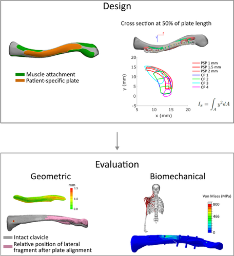
An overview of the applied methods can be found in Figure 1. Before the design process, a fourth generation composite clavicle (Sawbones) was CT scanned (Siemens, Somatom force, 0.75 mm slice thickness), segmented, and remeshed using Mimics Innovation Suite (Materialise).
2.1 Design process
The geometry of the patient-specific plate (PSP) was based on the fourth generation composite clavicle and accounted for the available fixation space between the muscle attachments on the superior side of the clavicle.21 To increase the plate's second moment of area and thus increase the stiffness against longitudinal bending, additional reinforcement at the anterior side of the fracture line was provided. The final plate geometry was defined based on these two aspects and is visualized in Figure 2.
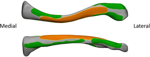
Plate thickness of the PSP was defined to best match stiffness of different CPs, to provide sufficient fracture stability and obtain a similar bending and torsional stiffness as in the CP. For the geometry shown in Figure 2, this resulted in a thickness of 1.5 mm. The thickness of the compared CPs varied from 2.3 to 3.4 mm, measured at the largest thickness occurring in the plate. The calculated bending and torsional stiffness values of PSPs with different thickness and CPs, can be found in Supporting Information Appendix 1.
2.2 Evaluation of geometric fit and anatomical outline
The geometric fit and anatomical outline after fracture reduction using PSP and CP were examined. To this end, a PSP defined only on the geometry was manufactured using single point incremental forming (SPIF),21 as this setup does not yet allow to manufacture titanium plates in the required thickness. A CP (Arthrex, 2651CL, this plate corresponds to CP 4 in Supporting Information Appendix 1) was selected and contoured by a medical doctor (S. N.) using plate bending pliers, to fit the intact composite clavicle's geometry, comparable to standard clinical practise. To evaluate the geometric fit and anatomical outline, both the PSP and CP were laser scanned (Nikon, LC60Dx) to create an STL file.
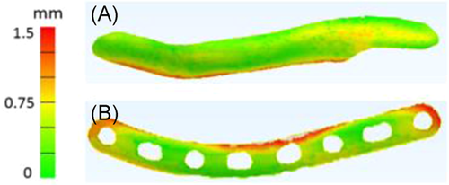
The geometric fit of the plates to the bone was evaluated as the average distance between the bone and the plate. To this end, both plates were digitally fitted to the intact clavicle using the local best fit with tolerances function in Gom Inspect (Gom), such that the plates did not intersect with the clavicle. The obtained configuration was then imported into 3-Matic (Materialise) and the distance between plates and intact clavicle was evaluated using “part comparison analysis.”
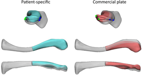
The anatomical outline was evaluated after fitting the medial and lateral bone fragment to the respective side of the plate. Therefore, a transversal fracture was created at 50% of the intact clavicle using 3-Matic, and the medial and lateral fracture fragments were fitted to the medial and lateral part of the plates respectively. Then, the medial part of the obtained construct was aligned back to the intact bone, and the difference in orientation of the lateral bone fragment with respect to the intact bone was quantified. This was performed (Figure 3) by measuring three angles in 3-matic between two lines fitted on four specific points, in both the intact bone and the lateral fragment. These angles represent how well the intact bone can be reconstructed using the plates. Angles are expressed in the coordinate system as shown in Figure 3.

2.3 FEM evaluation of plate strength, fatigue, and IFM
To investigate the mechanical performance of the CP and PSP, finite element models (FEMs) were created of the fractured clavicle reconstructed with both plates.
The PSP was based on the design file. The FE mesh of the CP was based on the STL file obtained by the laser scanner. The bone geometry was taken from the segmented CT scan for which the PSP was designed. Using a musculoskeletal-based approach,22 a fracture orientation from superomedial to inferolateral was found to be the least self-stabilizing. Hence, this orientation was created in the FEM.
In total four FEMs were created, which are visualized in Figure 4. These models will be further referred to as PSP 0 mm—PSP without a fracture gap, PSP 5 mm—PSP with a 5 mm fracture gap, CP 0 mm—CP without a fracture gap, and CP 5 mm—CP with a 5 mm fracture gap. The fracture gap size was modeled as 0 and 5 mm to mimic cases of direct and indirect fracture healing respectively.23
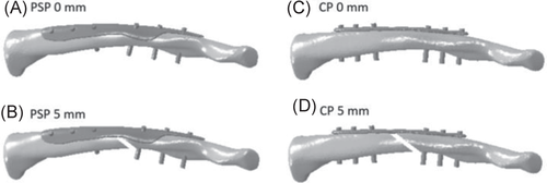
Mechanical loading was then imposed. The boundary condition (BC) coordinate system (CSYS) had its origin in the center of the sternoclavicular joint (SCJ) and its z-axis connecting the acromioclavicular joint (ACJ) center and the SCJ center. The SCJ was constrained in all directions, while the ACJ could only translate along the z-axis. These boundary conditions were equivalent to Cronskär et al.24 The loading conditions were identified using a musculoskeletal modeling-based approach.22 Muscle and joint reaction forces were calculated based on 3D marker data for seven activities of daily living (ADL) in three subjects. The seven loading conditions of interest were: unloaded and loaded anteflexion, unloaded and loaded abduction, combing hair, moving a coffee pot, and put a weight on a shelf. For each subject, the muscle and joint reaction forces occurring at three distinct time points, corresponding to the two maxima and the local minimum of the AC joint reaction force, were selected for each movement.22 The respective muscle and reaction forces comprised 63 force sets, which were imposed to the four FEMs as concentrated forces on a single node, which represents the center of gravity of the corresponding muscle attachments or joint centers. Numerical values of the three selected time points of all ADL from the three subjects, as well as their corresponding kinematics, can be found in Supporting Information Appendix 2.
Cortical bone was modeled as transverse isotropic linear material with the plane of isotropy oriented in the xy-plane and the longitudinal axis oriented in the z-direction. The assigned cortical material properties were Exx = Eyy = 10 GPa, Ezz = 12.88 GPa, Gxz = Gyz = 4.58 GPa and ν = 0.26.25 Trabecular bone and fixation plates were modeled as isotropic linear material with an E modulus of 155 MPa and 115 GPa (Ti6Al4V, further referred to as Ti), and a Poisson coefficient of 0.26 and 0.3 respectively (Sawbones).20
The interaction properties can be found in Table 1.
| Contact pair | Type of contact | Default Friction coefficient | Reference |
|---|---|---|---|
| Plate–bone | Frictional | 0.4 (Ti-bone) | Pendergast and Rusovici20 |
| Screw–plate | Frictional (0 mm gap)—Tied (5 mm gap) | 0.36 (Ti-Ti)—no friction coefficient | Pendergast and Rusovici20 |
| Screw–bone | Tied | – | Pendergast and Rusovici20 |
| Bone–bone | Frictional | 0.91 | Zhang et al. (1999)26 |
Screws were modeled as 3.5 mm diameter cylinders without thread, as it is shown that modeling the thread has relatively little influence on the global model behavior.20 Six screws were used to fixate the plate to the bone, three on each side of the fracture. In case of the CP, screws were positioned at the locations of the provided holes. For the PSP, screws were positioned equidistant from each other, maximally spread in each fragment.
The optimal mesh size was determined through convergence analysis. The convergence criteria to determine optimal mesh size were strain energy density, and average and maximal von Mises stress. Based on these criteria, the bone contained about 150.000 elements and the plates about 130.000. FE analysis was performed in Abaqus (v6.14, Dassault Systèmes, France).
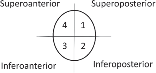
Biomechanical performance of the implant was assessed based on plate stresses and IFM during ADL. The stresses are related to plate strength and fatigue: (1) To evaluate plate strength, maximal von Mises stress in the plates was compared with the yield and ultimate tensile strength of Ti, and the average von Mises stress in the PSP was compared with the CP; (2) As no dynamic simulations were performed and a linear isotropic elastic material model was used for Ti, the range of principal stresses was further examined given its relationship with fatigue life measurements. To this end, for each force set, the element in which the maximal and minimal principle stress occurred was identified. Subsequently, for each of these elements, the range between maximal and minimal principal stress over all ADL was evaluated. The largest identified range was then compared with published S-N curves of Ti.27, 28 (3) IFM depends on plate stiffness and affects fracture healing. Therefore, the displacements between the two fracture fragments were assessed. The nodal coordinates of the medial and lateral surfaces of the fracture gap in initial and deformed position were divided into four quadrants in Matlab (Figure 5). For each quadrant, the center of gravity was calculated based on the nodal coordinates, and the distance between corresponding quadrants of the medial and lateral fragments was calculated. These distances were compared between the CP and PSP.
3 RESULTS
3.1 Geometric fit and anatomical outline
The mean geometric fit of the PSP was 0.47 mm (±0.23 mm), while the CP fit was 0.63 mm (±0.38 mm), as shown in Figure 6.
A better anatomical outline of the fracture fragments to the bone was achieved using the PSP than using the CP (Figure 7). More specific, the use of the PSP reduced the torsion angle (Table 2).
| X | Y | Z | |
|---|---|---|---|
| Patient-specific | 2.04° | −0.91° | 3.25° |
| Commercial | 3.37° | 3.82° | −11.31° |
3.2 Strength
The average von Mises stresses in the PSP and CP for 0 mm and 5 mm gap are presented in Tables 3 and 4, respectively. These tables show that the average von Mises stress is reduced in the PSP compared to the CP for both fracture gap conditions. For both the CP and PSP, the average von Mises stress in the constructs without a fracture gap was lower compared to constructs with a fracture gap. The peak von Mises stress over all ADL was 1170 (CP0), 1158 (PSP0), 1870 (CP5), and 1080 (PSP5) MPa, respectively. These values exceed the yield strength of Ti6Al4V. The peak von Mises stress for all cases can be found in Supporting Information Appendix 3.
| Frame 1 | Frame 2 | Frame 3 | ||||||||
|---|---|---|---|---|---|---|---|---|---|---|
| Plate | Movement | Sub. 1 (MPa) | Sub. 2 (MPa) | Sub. 3 (MPa) | Sub. 1 (MPa) | Sub. 2 (MPa) | Sub. 3 (MPa) | Sub. 1 (MPa) | Sub. 2 (MPa) | Sub. 3 (MPa) |
| CP | Unloaded anteflexion | 48.9 | 60.6 | 88.4 | 17 | 17.7 | 20.2 | 45.1 | 72.1 | 81.2 |
| Loaded anteflexion | 83.4 | 84.7 | 114.3 | 23.4 | 36.2 | 29.8 | 102.1 | 88.3 | 117.3 | |
| Unloaded abduction | 36.9 | 60.8 | 43.7 | 12.7 | 23.3 | 20.2 | 48.2 | 62.8 | 66.2 | |
| Loaded abduction | 80.9 | 80.2 | 59.3 | 23.3 | 19.3 | 19.9 | 83 | 85 | 92.9 | |
| Combing hair | 14.5 | 29.6 | 28.1 | 18.2 | 18.2 | 21.2 | 41.4 | 50.4 | 24.1 | |
| Moving coffee pot | 77.8 | 71.7 | 96.9 | 73.5 | 88 | 91.1 | 80 | 84.3 | 76.5 | |
| Put weight on a shelf | 29.7 | 45.9 | 27.8 | 82.5 | 45.5 | 73.3 | 36.9 | 46.3 | 46.8 | |
| PSP | Unloaded anteflexion | 19.3 | 26 | 50.4 | 14.6 | 16.5 | 18.7 | 20.8 | 34.1 | 40.9 |
| Loaded anteflexion | 37.2 | 38.2 | 68.3 | 20 | 28.5 | 23.1 | 59.4 | 42.1 | 66.8 | |
| Unloaded abduction | 26.5 | 44 | 32.6 | 12.2 | 21.6 | 19.9 | 28.2 | 44.7 | 49.2 | |
| Loaded abduction | 63.2 | 63.1 | 44.4 | 13 | 18.4 | 19.3 | 62.2 | 62.8 | 74.1 | |
| Combing hair | 14.1 | 13 | 13.7 | 18.3 | 15.3 | 10.3 | 18.1 | 21.1 | 22.1 | |
| Moving coffee pot | 36.5 | 30.9 | 51.9 | 34.7 | 43 | 47.4 | 41.3 | 40.7 | 37.2 | |
| Put weight on a shelf | 14.2 | 19.6 | 13 | 52.4 | 19.7 | 41.7 | 18.6 | 19.1 | 22.8 | |
| Frame 1 | Frame 2 | Frame 3 | ||||||||
|---|---|---|---|---|---|---|---|---|---|---|
| Plate | Movement | Sub. 1 (MPa) | Sub. 2 (MPa) | Sub. 3 (MPa) | Sub. 1 (MPa) | Sub. 2 (MPa) | Sub. 3 (MPa) | Sub. 1 (MPa) | Sub. 2 (MPa) | Sub. 3 (MPa) |
| CP | Unloaded anteflexion | 55.2 | 65.6 | 94.4 | 42.3 | 54.6 | 67.0 | 49.5 | 76.2 | 85.7 |
| Loaded anteflexion | 89.4 | 90.3 | 120.4 | 62.9 | 110.9 | 56.0 | 107.1 | 92.6 | 121.6 | |
| Unloaded abduction | 41.9 | 67.3 | 49.7 | 37.1 | 96.9 | 59.2 | 53.2 | 69.1 | 72.5 | |
| Loaded abduction | 87.9 | 87.2 | 65.7 | 24.0 | 58.7 | 55.3 | 89.4 | 91.6 | 99.7 | |
| Combing hair | 36.2 | 38.5 | 36.2 | 44.3 | 37.4 | 22.3 | 45.4 | 54.6 | 92.7 | |
| Moving coffee pot | 83.3 | 76.7 | 102.8 | 76.1 | 93.2 | 92.7 | 85.1 | 87.1 | 68.2 | |
| Put weight on a shelf | 38.4 | 52.4 | 36.0 | 87.9 | 49.9 | 77.6 | 34.7 | 50.7 | 43.1 | |
| PSP | Unloaded anteflexion | 32.8 | 36.3 | 63.1 | 40.6 | 46.9 | 55.5 | 30.0 | 43.8 | 52.4 |
| Loaded anteflexion | 42.8 | 52.2 | 83.4 | 55.6 | 92.2 | 55.7 | 73.2 | 54.8 | 81.8 | |
| Unloaded abduction | 31.4 | 53.2 | 38.5 | 35.8 | 72.2 | 54.3 | 35.1 | 53.4 | 58.1 | |
| Loaded abduction | 74.1 | 73.4 | 53.2 | 18.6 | 53.2 | 52.7 | 73.3 | 74.3 | 85.9 | |
| Combing hair | 38.3 | 20.2 | 19.0 | 46.6 | 41.2 | 13.7 | 24.8 | 28.6 | 74.3 | |
| Moving coffee pot | 49.6 | 41.5 | 65.7 | 42.8 | 55.6 | 53.7 | 52.6 | 50.8 | 37.4 | |
| Put weight on a shelf | 26.0 | 31.0 | 23.6 | 63.4 | 28.0 | 50.6 | 24.8 | 27.6 | 24.7 | |
3.3 Fatigue
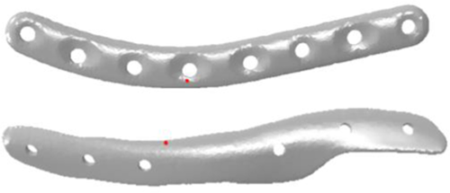
As shown in Table 5, the amplitude of the maximal and minimal principal stress was lower in the PSP than in the CP. Table 5 presents the largest maximal and minimal principal stress occurring in one specific element and its amplitude over all simulated ADL and all subjects. For CP 0 mm and CP 5 mm, the highest values occurred in an element close to the screw hole located at the fracture line, at the top side of the plate. For PS 0 and 5 mm, the element presenting the largest range, was located at the infero-posterior side, close to the fracture line. The maximal and minimal principal stresses for each subject is shown in Table 5. The location of these elements is visualized in Figure 8.
| Subject 1 | Subject 2 | Subject 3 | |||||||
|---|---|---|---|---|---|---|---|---|---|
 (MPa) (MPa) |
 (MPa) (MPa) |
Amplitude(MPa) |  (MPa) (MPa) |
 (MPa) (MPa) |
Amplitude(MPa) |  (MPa) (MPa) |
 (MPa) (MPa) |
Amplitude (MPa) | |
| CP 0 mm | 162.8 | −1076.2 | 619.5 | 264.9 | −1014.3 | 639.6 | 182.7 | −1205.8 | 694.3 |
| PSP 0 mm | 764.3 | −61.5 | 412.9 | 766.4 | −61.0 | 413.7 | 898.1 | −47.0 | 472.6 |
| CP 5 mm | 1026.3 | −1064.4 | 1045.4 | 1914.9 | −994.8 | 1454.9 | 1614.7 | −1183.3 | 1399.0 |
| PSP 5 mm | 715.6 | −545.1 | 630.3 | 530.4 | −1156.0 | 843.2 | 819.3 | −749.7 | 784.5 |
In case the movements with additional mass and above shoulder height were neglected, the stress amplitude was reduced to 305, 372 and 561 MPa in CP 0 mm for the three subjects, and to 185, 265 and 319 MPa in PSP 0 mm. In case of a fracture gap, the stress amplitude reduced to 538, 371, and 1273 MPa for the CP and to 338, 268, and 645 MPa for the PSP.
3.4 IFM
The relative displacements between the quadrants in case of a 0 mm and a 5 mm gap are shown in Figures 9 and 10, respectively. In both cases, with and without fracture gap, the constructs with the PSP behaved stiffer, as the displacements between the fragments were smaller than in the constructs with the CP. Additionally, substantial differences in IFM was present dependent on the patient-specific loading conditions. The maximal displacement in the constructs without fracture gap occurred during loaded abduction in PSP 0 mm and was equal to 1.286 mm. In CP 0 mm, the maximal displacement was equal to 2.926 mm and occurred during loaded anteflexion. In case a fracture gap was present, the maximal displacement in PSP 5 mm occurred during loaded abduction and was 1.039 mm. In case of CP 5 mm, the maximal displacement occurred during loaded anteflexion and was 2.317 mm.
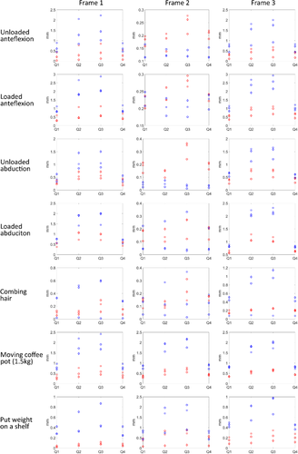
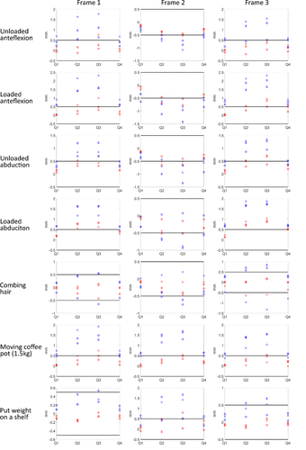
The displacements in the four quadrants showed in case of both the PSP and the CP that generally most displacements occurred in quadrants 2 and 3, and the least displacements were present in quadrants 1 and 4, indicating that the bone is subject to bending in the frontal plane.
4 DISCUSSION
The goal of this study was to investigate the potential of enhanced performance of a PSP compared to a CP, and to support a novel methodology for the design of a patient-specific clavicle fracture fixation plate. Evaluation showed a better geometrical fit and anatomical reconstruction, better resistance against fatigue, as well as lower average and peak von Mises stress and a lower IFM in the PSP. These results indicate a superior mechanical performance of the PSP compared to the CP in all aspects, while also better aligning with the patient-specific geometry and without the need for MAS detachment.
The superior anatomical fit indicates that the geometry of the PSP helps reducing the fracture fragments in their original anatomical position, provided the accurate manufacturing of the plate. In case of the PSP, this plate can act as a template to facilitate fracture reduction. An optimized positioning and control of the clavicular position is crucial as the clavicle's motion is linked to the scapula's motion. Changes in the resting position of the clavicle lead to a changed position of the scapula, which can cause scapular dyskinesis and pain during arm movement. Additionally, scapular malpositioning may change the orientation of the glenoid.29 However, it is still unclear which level of clavicle malunion leads to a clinically significantly altered scapular position and a poor functional result.30 As the PSP is designed to avoid interference with the MAS, also partial detachment of the MAS should no longer be needed. Apart from the improved fit and preservation of the MAS, the PSP geometry, which is based on the shape of the intact clavicle and its MAS, better withstands the loading conditions of the investigated ADL than the CP. This is shown by the lower average and peak von Mises stress in PSP than in CP.
Comparison of the FEA results with literature is difficult. Most studies on clavicle fracture fixation plates evaluate the stiffness of different constructs to compare different plating techniques12-14 The structural stiffness is calculated by dividing the applied caudally oriented load by the measured or simulated displacement of the lateral fragment. However, it does not allow documenting the plate behavior upon mechanical loading. Therefore, this study evaluated strength and fatigue, which are related to the occurring stresses, and IFM as a measure of plate effectiveness.
With respect to strength the PSP was found to perform better than the CP for the investigated loading conditions, as the CP with and without fracture gap more frequently exceeded the yield and ultimate strength of Ti. As can be expected, the average von Mises stresses were generally lower in the models without a fracture gap, as load sharing between plate and fragments is possible. Cronskär et al. examined the strength of clavicle fracture fixation devices, and showed a peak von Mises stress of 642 MPa in a superior clavicle plate. This value was obtained during a static eating motion. The ADL that most resembles an eating motion in this study is combing hair, presenting peak von Mises stresses of 423 MPa in case no fracture gap was present. This value is comparable to Cronskär.24 Other studies that investigated the peak von Mises stress in clavicle fracture fixation plates imposed a caudally oriented force of 100–250 N on the lateral fragment to represent arm weight, and clamped the medial fragment.12-14 This force is in the same order of magnitude as the forces resulting from the musculoskeletal modeling, however, from musculoskeletal modeling, also forces in other directions than caudal are present.22 Additionally, the reported peak von Mises stress in a study was 2825 MPa,13 and indicates that the plate is almost certainly not strong enough to carry the weight of the arm as this value exceed the ultimate tensile strength of Ti6Al4V. Nevertheless, patients do not always have to wear a sling postoperatively, therefore indicating that current fracture fixation plates can thus resist this load. This contradiction indicates the need of better defined and more physiological loading conditions for clavicle fracture fixation plate design.
The second aspect concerns fatigue. The principal stress range was lower in the PSP than in the CP, meaning that more movement cycles would be allowed with the PSP compared to the CP. From published S-N curves of Ti (several alloys and grain sizes)27, 28 it is clear that grain size, production process and surface treatment influence fatigue. Regardless of these properties, with a stress amplitude over all ADL of more than 1000 MPa in case of CP 5 mm (Table 5), only a limited number of cycles of these movements would be allowed before the plate would fail. Depending on the material, production process and surface treatment, the ranges obtained by neglecting movements above shoulder height and additional mass in the PSP, would allow an infinite number of cycles without failures.
The third aspect is IFM. In the majority of the ADL, both in the 0 and 5 mm fracture gaps, the PSP performed better than the CP in all ADL, as the displacements between fracture fragments were smaller for the PSP. The concept of IFM or fracture stability is crucial in fracture surgery, as the degree of stability determines the healing type at the fracture site. The interfragmentary strain (IFS) theory of Perren et al. states that primary bone healing occurs in case of absolute stability and secondary bone healing or callus formation occurs in case of relative stability.31 Absolute stability corresponds to a maximum interfragmentary strain of 2%, and relative stability corresponds to a strain of 2%–10%. Strains higher than 10% will lead to tissue rupture.23 For the 5 mm gap, 10% IFS corresponds to a displacement of 0.5 mm. As Figure 10 shows, the displacements in the PSP are closer to achieving relative stability than in the CP. It must be kept in mind that an immediate postoperative situation was modeled in this study and thus no new bone or callus was modeled. Pendergast et al. also investigated IFS for a superior clavicle fracture fixation plate, but with callus. They found a strain of 9.5% with a plate thickness of 4.5 mm, callus strain was evaluated using a 20 N caudally oriented force on the acromion while the medial end was clamped. Comparison with this study is thus difficult. To get better insight in whether or not fracture healing will occur, fracture healing models should be implemented32-34 to predict the dynamics of fracture healing.
Although these are promising results, some limitations must be considered. First of all, the design process was only tested for one sample. The 3D geometry of a composite clavicle was used because the subject-specific bone geometry of the subjects from which the musculoskeletal model was created,22 was unknown. Additionally, the loads were thus estimated using a scaled generic model. However, results from Wesseling et al. showed that including patient-specific geometrical detail is most important to calculate hip reaction forces.35 It should be investigated if geometrical detail has the same influence in the musculoskeletal model of the upper limb. A second limitation is the assumption of the plate material. Material properties after SPIF should still be investigated. Therefore, in this study, linear isotropic material properties with an E modulus of 115 GPa and a Poisson coefficient of 0.3 for Ti were assumed, as this material model is used in most FE studies examining fracture fixation plates13, 20 A third important limitation is validation. Each of the parameters in the FE model should be validated. These parameters include material properties of bone and plate, loading conditions, boundary condition, and interaction properties. The last limitation concerns the implementation in clinical practice. Creating patient-specific musculoskeletal models is time-consuming and might be unfeasible. Therefore, the level of subject-specificity in the musculoskeletal modeling workflow necessary for the design process has to be identified. This level of subject-specificity applies to the use of patient-specific motion capture and the level of subject-specific detail in the musculoskeletal model. However, as most clavicle fractures are not directly operatively treated, time for the design and production process will be available, thereby making the proposed workflow a promising tool of clavicle fracture treatment.
In this study, a thin patient-specific and commercial clavicle fracture fixation plate were compared using an in silico approach. Biomechanical evaluation by comparison of the PSP and CP showed a superior performance of the PSP in terms of anatomical fit, strength, fracture stability, and fatigue, despite its reduced thickness. Due to the patient-specific geometry and low profile, these fixation plates are expected to decrease the operation time as intraoperative contouring will become irrelevant, and decrease reoperation rates as implant irritation will be minimized. As medicine evolves more and more toward personalized treatment36, 37 the workflow of these PSP are worth future examination.
ACKNOWLEDGMENTS
The authors thank KU Leuven for providing funding through the BioMeTIOm IDO project and the Materialise Chair for image-based patient-specific biomechanics for access to Mimics and 3-Matic. The authors also thank Walter Coudyzer of the radiology department of the University Hospital Leuven for providing us with the CT scan from which the clavicle was segmented, and the companies Stryker, Arthrex and Johnson & Johnson for providing clavicle fixation plates.
CONFLICT OF INTERESTS
Prof. S. Nijs reports grants from DePuy Synthes as well as personal fees from DePuy Synthes, Zimmer Biomet, and Mathys Medical that are outside the submitted work. The remaining authors declare that there are no conflict of interests.
AUTHOR CONTRIBUTIONS
Sanne Vancleef contributed to research design, acquisition, analysis and interpretation of data, and drafting the paper. Mariska Wesseling contributed to interpretation of the data, and revising the paper. Stefaan Nijs, Joost R. Duflou, lse Jonkers, and Jos Vander Sloten contributed to research design, analysis and interpretation of data, and revising of the paper. All authors have read and approved the final submitted manuscript.


