The promoting effect of Fe on Ni/GDC for the Solid Oxide H2O electrolysis
Funding information: Fuel Cells and Hydrogen Joint Undertaking, Grant/Award Numbers: NewSOC/874577, SElySOs/671481
Summary
The study deals with the modification of commercial Ni/GDC powder with iron and its use as fuel functional electrode for Solid Oxide H2O electrolysis. The Fe-NiO/GDC samples were prepared with the Deposition-Precipitation method and characterized, in their oxidized and reduced form, by using BET, HR-TEM, SAED, XRD, XPS and TG analysis in the presence of H2O. The electrochemical investigation deals with the comparison of single SOECs at 900°C, under various pH2O/pH2 ratios. In the oxidized powders iron was detected, both in the bulk and on the surface, in the form of crystallized Fe2O3 species, which during H2-reduction interacted with NiO towards the formation of a Ni-Fe alloy. The latter promoted the electrochemical performance of the Fe-Ni/GDC electrodes, where there are indications of strong dependence on the Fe wt% content. Specifically, the performance of the cell with 0.5 wt% Fe-Ni/GDC was threefold higher than that with Ni/GDC. On the other hand, the cell with 2 wt% Fe-Ni/GDC was worse, implying that the promoting effect of Fe lies on quite low wt% content. Finally, the examined Fe-doped electrodes exhibited increase of polarization in high pH2O. This is primarily ascribed to the fact that Fe-Ni/GDC electrodes seem more susceptible to H2O oxidation. Overall, Fe is considered as a promising Ni/GDC dopant, capable to substitute noble metals like Au, but further investigation is required for the elucidation of key preparation and performance parameters.
1 INTRODUCTION
 (1)
(1) (2)
(2)Currently, the most commonly used electrocatalyst as fuel electrode for SOECs is nickel-yttria stabilized zirconia (Ni/YSZ), due to its high electronic conductivity, adequate activity for the electrochemical reduction of water and low cost. However, the presence of high steam concentration, during prolonged H2O electrolysis, has a detrimental effect on the stability of Ni/YSZ electrodes.5-9
In recent years, novel Ni-based materials are continuously being proposed as candidates for the fuel electrode in SOECs. Moreover, the replacement of ZrO2(Y2O3) (YSZ) with a porous mixed ionic-electronic conductor (MIEC) material, which can also act as an electrocatalyst, has been considered as a method to increase the reaction sites of the electrocatalyst. Gadolinium-doped ceria, CeO2(Gd2O3) (GDC), is a quite suitable MIEC material for this purpose, since it combines good electronic and ionic conductivity with high electrochemical activity8-11 and fast interfacial charge transfer reactions, which could prove to be beneficial for the performance of the fuel electrode.12, 13
Another promising approach in the field of high temperature Solid Oxide fuel cells is to promote the electrocatalytic activity of Ni-based electrodes, through the dispersion of small amounts of noble (eg, Pt, Pd, Rh, Ru, Au) or non-noble transition metal elements (eg, Sn, Cu, Mo, Bi).9, 14 There are also similar trends in the field of low temperature (liquid) water electrolysis applications, such as those recently published by K. S. Bhat and H. S. Nagaraja, who reported nickel chalcogenides15 (sulfides, selenides and tellurides) as promising substitutes of the State of the Art (SoA) (Pt, IrO2, RuO2) electrocatalysts, as well as formulations based on copper sulfide-nickel sulfide arrays.16 Albeit the status of modified Solid Oxide Ni-based fuel cell electrodes, the research level in the case of electrolysis is currently in progress. Indicatively, there are recent experimental studies reporting that the electrocatalytic performance of Ni-based fuel electrodes for H2O or CO2 electrolysis and H2O/CO2 co-electrolysis can be improved through alloying with metals such as Rh, Ru, Co and Pd.17-22
Following the above approach, binary 3 wt% Au-Ni/GDC8 and ternary 3 wt% Au-3 wt% Mo-Ni/GDC9 samples were recently investigated by our research group as potential fuel electrodes for the H2O electrolysis process and exhibited improved electrocatalytic performance, compared to Ni/GDC. However, gold is a precious metal and therefore not very well accepted for commercial use, due to its high cost. Hence, it is important to explore the electrocatalytic activity of different, non-precious, transition metal elements, where our recent efforts have focused on the experimental study of iron.
Our research interest in iron initiated from theoretical investigations, based on Density Functional Theory (DFT) calculations, such as the studies by Gu et al23 and Cho et al24 who dealt with the identification of potential Ni-based materials as Solid Oxide fuel electrodes for the H2O electrolysis and H2O/CO2 co-electrolysis processes. Specifically, for the case of Solid Oxide H2O electrolysis, the Ni-Fe alloy was indicated23 as a candidate with higher activity than Ni.
There are also research publications, where the Ni/Fe combination has been experimentally studied in various formulations/materials for several applications. Indicatively, the group of Ishihara25-27 reported the enhancing effect of separate Ni-Fe bi-metallic electrodes, which were added together with perovskite fuel electrodes, such as Sm0.5Sr0.5CoO3 for Solid Oxide H2 oxidation26 and Ba0.6La0.4CoO3 for the Solid Oxide H2O electrolysis25 and CO2 electrolysis27 reactions, based on LaGaO3 perovskite electrolyte.
Other cases dealt with Ni0.75Fe0.25 + Sm0.2Ce0.8O1.9 (60:40 v/o) formulations that were examined by Wu et al28 for the H2 oxidation at 450°C to 650°C and Ni-Fe + Ce0.85Sm0.15O3-δ (60:40 v/o) compositions, which were investigated by Ji Yu et al29 as fuel electrodes for Solid Oxide H2O electrolysis at 700°C to 800°C. Specifically, in the latter case the rich in iron (~23 wt% Fe) Ni0.6Fe0.4 + Ce0.85Sm0.15O3-δ formulation exhibited the optimum performance.29 The beneficial effect of iron was also studied by Jeong et al,30 who applied infiltration of high amounts of Fe to a Ni/YSZ fuel electrode, towards the promotion of the CO2 reduction process, as well as the electrochemical performance and stability for the Solid Oxide H2O/CO2 co-electrolysis reaction.
Similarly rich in iron (such as ~37 wt%) Ni-Fe combinations supported on Ce0.2Gd0.8O (GDC) have been examined by Frontera et al,31 as catalysts for the simultaneous methanation of carbon oxides and by Lo Faro et al32 as a separate catalytic pre-layer, with an atomic ratio of Ni/Fe = 1, on top of the actual Ni/Y0.08Zr0.92O (Ni/YSZ) fuel electrode for enhancing the in-situ methanation of CO2. Another interesting application of Fe (1 and 40 wt%) and Ni (5-10 wt%) combination with GDC was reported by Simonsen et al,33 who characterized this formulation as a potential fuel electrode for metal-supported SOFC/SOECs. Furthermore, small amounts of NiO (~1 wt%) and FeO (~1 wt%) co-infiltrated on a Sr0.94Ti0.9Nb0.1O0.3 (STN94) backbone were studied by Drasbæk et al34 either in the absence of GDC under 4% H2O/H2 and 50% H2O/H2 mixtures, or in the presence of GDC35 under 4% H2O/H2, 50% H2O/H2 and 50% CO2/CO.
The primary aim of the presented study is to investigate the potential to substitute Au8, 9 by the transition element of Fe in Ni/GDC fuel electrode for the Solid Oxide H2O electrolysis reaction. Compared to other experimental studies, dealing with Ni/Fe configurations, herein there is focus on enhancing the activity of a commercially available (SoA) NiO/GDC powder, rich in nickel oxide (65 wt%), by means of Deposition-Precipitation. One of the advantages of this method is that it can be applied on readily available powders/cermets and allows doping with pre-calculated amounts of the selected modifier with accuracy and repeatability. Consequently, it can be applied for large-scale powder production. The first objective is to clarify whether iron can be deposited through the selected preparation method and which are the possible formulations in the oxidized and reduced form of the resulting powder. Sequentially, the latter material is applied as the, sole, functional fuel electrode in a single solid oxide cell and there is investigation of the iron-modification and of the wt% loading effects on the electrochemical performance, alongside with a comparison to the reported9 noble-metal based modification of Au-Mo in Ni/GDC.
2 EXPERIMENTAL
2.1 Deposition of Fe on NiO/GDC electrocatalysts
The X wt% Fe deposition on NiO/GDC (X = 0.5 and 2) was achieved via the Deposition-Precipitation (D.P.) method. Commercial NiO/GDC powder (65 wt% NiO—35 wt% GDC, Marion Technologies) was used as the support. The applied precursor salt was Fe(NO3)3 × 9H2O (Sigma-Aldrich), which was diluted in 3-Distilled H2O in order to prepare the appropriate solutions. The NiO/GDC powder was immersed into 3-Distilled H2O and the resulting suspension was mildly stirred with the temperature adjusted to 70°C. The Fe-solution was dropwise added in the suspension and the pH value was continuously adjusted in the region of 8.1 ± 0.2,36 by adding the proper amount of aqueous NH3 1 M solution as the precipitant agent.37 The deposition of 3 wt% Au-3 wt% Mo on NiO/GDC powder was achieved with the Deposition-Co Precipitation (D.CP.) method, as described elsewhere.9 In each case, after filtering, the precipitate was mildly washed, in order to eliminate any residual Cl− anions, and sequentially it was dried at 110°C for 24 hours. All dried powders were calcined at 600°C for 90 minutes and a part of them at 1100°C for 75 minutes, in stagnant air. The latter batch was used for the physicochemical characterization, in an attempt to examine the samples after being subjected at temperatures similarly high to those where the cells are prepared, while the former batch was used for the paste preparation that was used for the screen printing of the Solid Oxide fuel electrodes. The examined specimens 0.5 wt% Fe-Ni/GDC, 2 wt% Fe-Ni/GDC and 3 wt% Au-3 wt% Mo-Ni/GDC will be noted in the sequence of the manuscript as 0.5Fe-Ni/GDC, 2Fe-Ni/GDC and 3Au-3Mo-Ni/GDC.
2.2 Preparation of single electrolyte-supported SOECs
The single electrolyte-supported cells comprised circular shaped planar 8YSZ (ZrO2 stabilized with 8 mol% Y2O3) electrolyte membranes (~25 mm diameter, ~150 μm thickness, provided by KERAFOL). The fuel and oxygen electrodes were deposited by means of the screen printing method. Specifically, for the fuel electrode, a paste (solids 60 wt%) was prepared by using a proper amount of X-NiO/GDC (where X: 0.5Fe, 2Fe or 3Au-3Mo), terpineol (Sigma-Aldrich) as the dispersant and PVB (polyvinylbutyral, Sigma-Aldrich) as the binder.9, 38 Similarly, the oxygen electrode was prepared by using a paste of La0.6Sr0.4Co0.8Fe0.2O3-δ (LSCoF) powder (provided by SOLIDpower). Furthermore, a barrier layer of Gd0.10Ce0.90O2-x (GDC10) (10 ± 1 mg/cm2) was applied on the YSZ electrolyte, at the oxygen side, and was pre-calcined at 1300°C/2 h with 2°C/min. After the screen printing of the electrodes, the cells were calcined at 1150°C/2 h with 2°C/min. The examined modified-NiO/GDC (10 ± 1 mg/cm2) and LSCoF (10 ± 1 mg/cm2) electrodes had an active area of 1.8 cm2 and a thickness of ~20 μm, as shown in previous studies.8, 9
2.3 Physicochemical characterization
The powders, in their oxidized (“as prepared”) and H2-reduced form, were characterized with BET (Brunauer-Emmett-Teller), HR-TEM/TEM (High Resolution-Transmission Electron Microscopy), SAED (Selected Area Electron Diffraction), XPS (X-ray Photoelectron Spectroscopy), XRD (X-ray Diffraction) and TGA (Thermogravimetric Analysis) in the presence of H2O. Specifically, the BET Specific Surface Area values (SSAs) were determined with the use of a Micromeritics TriStar 3000 apparatus, employing nitrogen physisorption at the temperature of liquid nitrogen (77 K). Prior to each measurement, the sample was outgased under dynamic vacuum at 250°C for 2 hours.
 (3)
(3)XPS measurements were carried out in an ultra-high vacuum system (UHV), equipped with a X-Ray Al/Mg gun and a Phoibos 100-1D-DLD energy analyzer. Unmonochromatized MgKα line at 1253.6 eV and an analyzer pass energy of 10 eV, giving a full width at half maximum (FWHM) of 0.85 eV for the Ag3d5/2 peak, were used in all measurements. The XP core level spectra were analyzed by using a fitting routine, which can decompose each spectrum into individual mixed Gaussian-Lorentzian peaks after a Shirley background subtraction. The atomic ratios were calculated from the intensity (peak area) of the XPS peaks, weighted with the corresponding relative sensitivity factors (RSF). For the spectra collection and treatment, including fitting, the commercial software SpecsLab Prodigy (by Specs GmbH, Berlin) was used. Errors in our quantitative data are found in the range of ~10% (peak areas), while the accuracy for BEs assignments is ~0.1 eV. The samples were in powder form and pressed into pellets, whereas the analyzed area was an ellipsoid of 7.0 × 15 mm2.
TGA measurements were performed in a TA Q50 instrument, isothermally at 800°C, under 15.5 vol% H2O/Ar, with a total flow rate of 100 cm3/min. The weight of the examined sample was ~50 mg and before the measurement it was reduced in-situ with 80 vol% H2/Ar, at 800°C for 100 minutes. After the H2-reduction period the reaction mixture was switched and steam was added in the feed, by passing a carrier gas (Ar) through a saturator that was maintained at a constant temperature (65°C), while H2 was no longer introduced.
2.4 Electrochemical measurements
The electrochemical performance of Ni/GDC, 0.5Fe-Ni/GDC and 2Fe-Ni/GDC samples was studied, in single SOCs at 900°C, where each sample was used as the only functional fuel electrode. H2O electrolysis conditions were formed, by feeding liquid water through a mass (liquid) flow controller, which was connected to a pressurized vessel. The latter system circulated water and vaporized it inside chambers, on-line with the experimental setup. All lines and valves were heated at 160°C to avoid H2O condensation. Ni and Pt meshes were used as current collectors on the fuel and oxygen side, respectively. Before each measurement, the fuel electrode was pre-reduced with 100 vol% H2 (Ftotal = 150 cm3/min) for 12 hours. The electrochemical experiments were carried out in galvanostatic mode through polarization (I-V) curves and simultaneous Electrochemical Impedance Spectra (EIS) recording, by using an AUTOLAB potentiostat/galvanonstat, model PGSTAT302N (serial number: 84693). The I-V measurements took place by varying linearly the current, between open circuit potential (O.C.P.) and −2.1 V, at a scan rate of 2 mA s−1 and step current of 20 mA. The EIS were recorded in galvanostatic mode at various current densities and pH2O/pH2 ratios with an amplitude of 20 mA in the frequency range from 100 kHz to 20 mHz.
3 RESULTS AND DISCUSSION
3.1 Physicochemical characterization
3.1.1 Effect of Fe-doping on the bulk phase of the powders
The Specific Surface Area (SSA) values of NiO/GDC, 0.5Fe-NiO/GDC and 2Fe-NiO/GDC, calcined in air at 600°C and 1100°C and reduced in H2 at 850°C/2 h, are presented in Table 1. All samples exhibit low SSA, which decreases further by increasing the calcination temperature from 600°C to 1100°C and after reduction with H2 at 850°C. The main remark is that modification of NiO/GDC with iron results in increased SSA values. In particular, the addition of 0.5 wt% Fe causes an increase in the SSA value of NiO/GDC39 equal to 30% at 600°C and 17% at 1100°C. Further deposition of 2 wt% Fe increases the SSAs by 66% and 38% at 600°C and 1100°C, respectively. The effect of Fe addition on the SSA values is retained after H2 reduction at 850°C, where the SSAs increase by 55% in the case of 0.5Fe-Ni/GDC sample and by 70% in the case of 2Fe-Ni/GDC, compared to Ni/GDC.
| Sample powder | SSABET (m2 g−1) | ||
|---|---|---|---|
| T = 600°C, (oxidized) | T = 1100°C, (oxidized) | After H2-reduction at T = 850°C | |
| NiO/GDC | 5.3 | 2.9 | 2.0 |
| 0.5Fe-NiO/GDC | 6.9 | 3.4 | 3.1 |
| 2Fe-NiO/GDC | 8.8 | 4.0 | 3.4 |
- Note: Error/accuracy = ±0.2 m2 g−1.
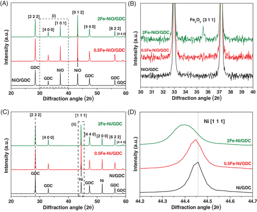
Iron deposition is further verified by means of XRD measurements (Figure 1). Specifically, Figure 1A,B shows the XRD patterns of the “as prepared” powders, calcined in air at 1100°C. Diffraction peaks of NiO (JCPDS 044-1159) and GDC (Gd0.6Ce0.4)2O3.2 (JCPDS 046-0508) are detected in all samples. The comparison of the samples in the magnified area (a), depicted in Figure 1B, reveals that Fe2O3 is detectable by XRD only for the 2Fe-NiO/GDC sample with a peak at 2θ = 35.6°, attributed to the [3 1 1] diffraction planes of Maghemite-C, syn-Fe2O3 (JCPDS 039-1346). The absence of Fe2O3 diffraction peaks in the 0.5Fe-NiO/GDC sample can be attributed to the low wt% content of Fe, which is below the XRD detection limit.
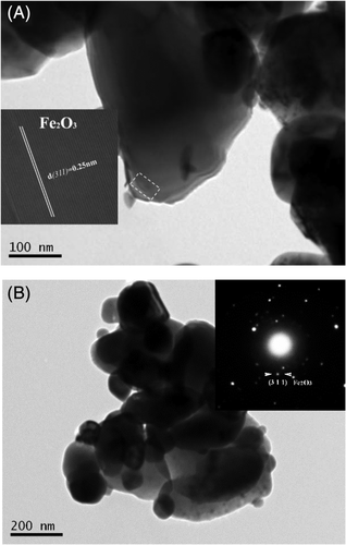
The morphology and structure of iron, in the oxidized form of the powders, was further investigated by HR-TEM/TEM and SAED. Representative TEM micrographs of the binary 0.5Fe-NiO/GDC and 2Fe-NiO/GDC, calcined in air at 1100°C, are depicted in Figure 2A,B, respectively. In consistency with the XRD results, the presence of Fe2O3 with Maghemite-C structure was confirmed by means of SAED for the 2Fe-NiO/GDC sample (inset of Figure 2B). HR-TEM study revealed that crystal Fe2O3 is also present in the powder with the lowest Fe content. In particular, the HR-TEM image of 0.5Fe-NiO/GDC (inset of Figure 2A) shows the interplanar spacing of 0.25 nm, which corresponds to the [3 1 1] plane of syn-Fe2O3. Therefore, it can be concluded that in the case of the “as prepared” powders, iron is in the form of well crystallized Fe2O3. This is also supported with the macroscopic images of the powders (Figure S1), where their color differed and followed the gradual increase in the wt% content of iron, due to the presence of well crystallized iron oxide.
The corresponding XRD patterns of the H2-reduced powders are presented in Figure 1C, including a magnified area of Ni (syn-Ni, JCPDS 004-0850) diffraction peak in Figure 1D. It is observed that after H2-reduction at 850°C, iron is no longer detectable by XRD, suggesting its possible absence as bulk particles and a rearrangement in the structure of the reduced material. This observation is in agreement with the literature,28, 30, 33, 40 where it is reported that a Ni-Fe alloy is formed during the reduction process. The above remark is further verified from a shift of the Ni [1 1 1] diffraction peak, at lower 2θ values for the Fe-modified samples (Figure 1D). Specifically, the incorporation of the larger atomic radius ions of Fe (1.40 Å) into the Ni (1.35 Å)41 lattice has been reported28 to cause an increase in the crystal lattice parameter value of the Ni-Fe phase. The latter effect is shown in the presented XRD patterns from a shift of the Ni [1 1 1] peak to lower 2θ values, which is ~0.01° for 0.5Fe-Ni/GDC and ~0.06° for 2Fe-Ni/GDC, compared to Ni/GDC. In particular, the lattice parameter values are estimated to be: 3.527, 3.528 and 3.532 Å for Ni, Ni-0.5Fe and Ni-2Fe, respectively. On the other hand, no shift is detected for the GDC [2 2 2] diffraction peak (Figure 1C).
The mean primary particle size (d) of the detected phases in the XRD patterns, was estimated according to the Debye-Scherrer equation (Equation 3) and the calculated values for NiO, Ni, GDC and Fe2O3 are presented in Table 2. It is observed that the particle size of GDC does not change after calcination, H2-reduction or after Fe addition, with a mean diameter of ~60 nm. The same remark applies for NiO with a mean diameter of ~115 nm. On the other hand, there is a gradual decrease of the Ni particle size in the H2-reduced samples, by increasing the wt% content of Fe. Specifically, the primary size of Ni decreases by 16% in the case of 0.5Fe-Ni/GDC sample and by 46% in the case of 2Fe-Ni/GDC. The observations from BET, XRD and HR-TEM/SAED measurements suggest an effect of iron both in the oxidized and the reduced bulk phase of the modified samples.
| Primary, mean, crystallite size, d, (nm) | |||
|---|---|---|---|
| NiO/GDC | 0.5Fe-NiO/GDC | 2Fe-NiO/GDC | |
| Oxidized, calcined at T = 1100°C | |||
| NiO | 116 | 115 | 114 |
| GDC | 60 | 61 | 58 |
| Fe2O3 | - | (Not detected) | 88 |
| After H2-reduction at T = 850°C | |||
| Ni | 128 | 107 | 69 |
| GDC | 61 | 58 | 59 |
3.1.2 Surface effect of Fe-deposition in the oxidized form of the powders
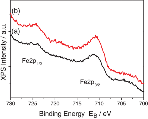
The effect of Fe on the surface chemical state of the powders, in their oxidized form, was examined by means of XPS analysis. Iron was also detected on the surface of the modified powders and Figure 3 shows the Fe2p doublet for 0.5Fe-NiO/GDC and 2Fe-NiO/GDC. The peak consists of one component at 711.0 eV, which is assigned to the Fe2O3 chemical state.42 The Ni2p-Ce3d regions of the Fe-modified powders, as well as of the unmodified NiO/GDC, are presented in Figure S2. Specifically, the Ni2p3/2 peak is centered at 855.5 ± 0.1 eV with a shake-up satellite at ~862 eV, which correspond to the NiO chemical state. The Ce3d u′′′′ shake up peak, for all samples, is centered at 916.8 eV and the intensity ratio of u′′′/Ce3d is 0.14 ± 0.05, indicating the presence of Ce4+ oxidative surface state.8, 9 Moreover, the XPS analysis showed that the relative surface atomic ratio of Fe/Ni is 0.054 (nominal ratio = 0.017) for 0.5Fe-NiO/GDC and 0.076 (nominal ratio = 0.068) for 2Fe-NiO/GDC. The three-times higher value of the Fe/Ni ratio in 0.5Fe-NiO/GDC, compared to the nominal, suggests that Fe2O3 is present in the form of small particles, which are highly dispersed within NiO/GDC. On the contrary, the measured Fe/Ni ratio in 2Fe-NiO/GDC is very close to the nominal, indicating higher and similar particle size of Fe2O3 to that of NiO, as also detected by the XRD analysis.
3.1.3 Oxidation tolerance of Fe-modified powders in the presence of H2O
 (4)
(4)The interaction takes place, initially, through the dissociative adsorption of H2O molecules on the surface. The resulting Oads species oxidize the surface of the sample, where subsequently there is oxygen diffusion and gradual oxidation of the bulk phase. The basic remark is that the stronger this interaction is, it results in higher oxidation rate by H2O.8, 9, 43-45
Figure 4 shows the TGA oxidation profiles of the pre-reduced Ni/GDC and Fe-Ni/GDC powders, represented by the weight increase (Δwt%) as a function of time. In general, the profiles can be interpreted in three segments.8, 9 The first takes place by introducing the H2O/Ar mixture, where there is a sharp, but low weight increase. This has been attributed8, 9 to the complete, bulk, oxidation of the partially reduced CeO2 in GDC (Ce3+ to Ce4+). The second segment corresponds to the consecutive ~13 minutes of operation, where the majority of the examined samples8, 9 remain in the reduced state without any weight increment. This segment is related8, 9 to the inhibited interaction of the adsorbed H2O molecules with the Ni surface, due to the presence of NiH species that were formed during the pre-reduction period of the powders. The dissociation of NiH, results in H2 desorption and the formation of Ni, which thereafter interacts with steam towards its gradual oxidation. The latter process corresponds to the third segment of the TGA profiles, after ~12 to 13 min of operation, where the weight of the samples steadily increases.
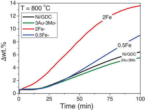
The first observation in Figure 4 is that both of the Fe-Ni/GDC samples were more susceptible to oxidation by H2O, compared to Ni/GDC. Specifically, 2Fe-Ni/GDC started to oxidize right after the introduction of the 15.5 vol% H2O/Ar mixture (at t = 0 min) and showed the highest (~14%) weight increase (at t = 100 min), approaching the full oxidation uptake of its weight. It is noteworthy that the oxidation profile of 2Fe-Ni/GDC did not proceed through the second segment, but right after the bulk oxidation of GDC. Thus, it can be suggested that the high loading in iron (2 wt%) Fe-Ni alloy either did not allow the formation/adsorption of NiH, or the concentration/coverage of these species was rather low and not enough to maintain the sample in its reduced state.
The 0.5Fe-Ni/GDC sample exhibited a milder H2O oxidation profile, compared to that of 2Fe-Ni/GDC, but still with a higher slope with respect to Ni/GDC. Specifically, after 100 min under 15.5 vol% H2O/Ar, the 0.5Fe-Ni/GDC exhibited higher oxidation ~8 Δwt%, instead of ~6 Δwt% for the unmodified powder, without approaching an equilibrium state as in the case of the other samples. Finally, there is also comparison with the reported case9 of the ternary 3Au-3Mo-Ni/GDC powder, which proved to be the least susceptible to oxidation in H2O/Ar and consequently the sample with the lowest interaction with the adsorbed H2O molecules.9
Overall, the surface and bulk characterization shows that modification of commercial (SoA) NiO/GDC powder is feasible and has the potential of scaling up, by means of the D.P. method. Crystal Fe2O3 is well dispersed within the oxidized phase of the NiO/GDC powder, which during H2-reduction interacts with NiO towards the formation of a Ni-Fe alloy. This interaction causes a concomitant increase of the SSA and a decrease of the primary Ni crystal size. In addition, the Fe-Ni/GDC powders are more susceptible to H2O oxidation, compared to Ni/GDC. In particular, modification with iron seems to enhance the interaction of the samples with H2O, whereas the increase in Fe wt% content resulted in faster and higher oxidation degree. The induced changes on the physicochemical properties of the Fe-modified samples are also investigated in relation to their electrochemical performance, as presented in the following section.
3.2 Electrochemical performance and discussion
The electrochemical performance of the prepared iron doped Ni/GDC samples was investigated for the Solid Oxide H2O electrolysis reaction on 8YSZ electrolyte supported cells (ESCs), with a two-electrode configuration. Fe-Ni/GDC was used as the only fuel functional electrode and the oxygen electrode was LSCoF, as described in the experimental part. In each measurement the cell was subjected to different pH2O/pH2 ratios, ranging from 1 up to 9, at 900°C. The comparison focuses on polarization I to V measurements and EIS analysis, in an attempt to evaluate the effects of iron modification on the electrochemical performance, including the polarization (Rpol) and ohmic (Rohm) resistances. For the proper cell comparison there was an effort to minimize the contribution from the O2 electrode, which might be a misleading factor particularly in the case of two-electrode configuration. Consequently, in each cell, specific attention was paid on (a) applying similar LSCoF loading (~ 10 mg/cm2) and (b) feeding the same and constant reaction conditions on the O2 electrode side.
Figure 5 presents the I-V comparison for the H2O electrolysis reaction under pH2O/pH2 = 1 (Figure 5A) and pH2O/pH2 = 9 (Figure 5B) at 900°C. The Open Circuit Potential (O.C.P.) values were ~ −0.949 V for pH2O/pH2 = 1 and ~−0.825 V for pH2O/pH2 = 9. The experimental values are in agreement with the theoretical ones, as predicted by the Nernst equation, corresponding to −0.948 V and −0.832 V, respectively, whereas similar experimental values have been observed in other studies.1, 9
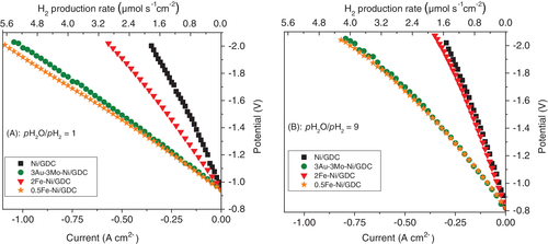
The I-V curves show that iron modification affects the electrochemical performance, in combination with the applied pH2O/pH2. In the case where the ratio is equal to 1 both cells with the iron-modified fuel electrodes performed better, compared to Ni/GDC. However, the wt% loading of iron proved to be an important parameter, because the cell comprising 0.5Fe-Ni/GDC performed much better and exhibited lower overpotential at the same applied current density, compared to 2Fe-Ni/GDC. By increasing the pH2O/pH2 to 9 the trend was the same, despite the fact that there was an overall decrease of the electrochemical performance for all cells. Moreover, the cell with the 2Fe-Ni/GDC fuel electrode exhibited higher decrease in performance, compared to the 0.5Fe-Ni/GDC, reaching the low performance of the unmodified Ni/GDC. The most interesting comparison in the IV curves is that the cell with the binary 0.5Fe-Ni/GDC sample performed similarly, to the ternary 3Au-3Mo-Ni/GDC fuel electrode. The latter has been thoroughly examined9 and its enhanced behavior was mainly attributed to the synergistic interaction between Au, Mo, Ni and the induced modifications on the structural properties and the electro-catalytic activity of the electrode for both the thermochemical H2O dissociation reaction and the electrochemical splitting of it.
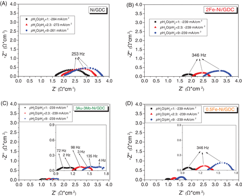
The effect of Fe-modification in parallel to the applied partial pressure of steam were also investigated in regards to the polarization (Rpol) and ohmic (Rohm) characteristics of the cells, by means of EIS analysis. The corresponding Nyquist plots are depicted in Figure 6, where there is also comparison with the ternary 3Au-3Mo-Ni/GDC fuel electrode.9 The spectra were recorded in galvanostatic mode at similar current density, in order to make sure that any differences observed in the spectra, are due to the variation in the operating conditions of the fuel electrode. The contribution of the polarization characteristics of the oxygen electrode will remain, practically, constant for the same O2− flux through the electrochemical interface of the electrode at the same temperature and partial pressure of O2. Τhe extracted Rohm and Rpol values from the Nyquist plots are also reported in Table 3.
| pH2O/pH2 | ||||||
|---|---|---|---|---|---|---|
| 1 | 2.3 | 1 | 2.3 | |||
| Rohm (Ω*cm2) | 9 | Rpol (Ω*cm2) | 9 | |||
| Ni/GDC | 1.64 | 1.9 | 2.05 | 1.36 | 1.53 | 1.64 |
| 3Au-3Mo-Ni/GDC | 0.92 | 1.21 | 1.38 | 0.34 | 0.34 | 0.36 |
| 0.5Fe-Ni/GDC | 0.91 | 1.12 | 1.32 | 0.22 | 0.30 | 0.42 |
| 2Fe-Ni/GDC | 1.63 | 2.06 | 2.54 | 0.53 | 0.74 | 1.16 |
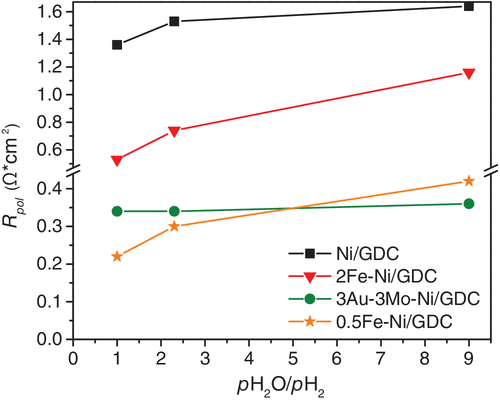
The promoting effect by Fe-modification is verified, as well as the dependence of the impedance characteristics on the Fe wt% loading. Specifically, the cell with 0.5Fe-Ni/GDC exhibited the lowest Rohm and Rpol values, compared to Ni/GDC and 2Fe-Ni/GDC, in all applied current densities and pH2O/pH2 ratios. The increase in the loading of iron to 2 wt% had a negative effect and caused an increment on the ohmic resistance values, particularly at high pH2O/pH2 = 9. Similar trend, but at lower extent, is observed in the case of the Rpol values, where their evolution is also depicted in Figure 7.
The low Rohm values for the cell with 0.5Fe-Ni/GDC are primarily ascribed to the observed interaction of Fe and Ni and the formation of the Ni-Fe alloy. Specifically, the low content in iron may result in better connectivity of the Ni network, thus improving the electrons conductivity. The increase in Rohm can be attributed to the increase of electronic, ohmic, resistance.8, 9 Particularly for the case of 2Fe-Ni/GDC, in comparison to 0.5Fe-Ni/GDC and Ni/GDC, the high Rohm can be ascribed to the larger amount of Fe, which results in the higher oxidation tendency by H2O and may lead to the formation of a less conductive layer on the Ni surface. This tendency is less pronounced in the case of the low loading 0.5Fe-Ni/GDC, at least for the examined period of the cells, highlighting the key dependence of the Fe promoting effect, which largely depends on the wt% loading of iron in the nickel lattice. In this respect, a more holistic interpretation, for both Rohm and Rpol, should deal with the induced changes on the structural/physicochemical properties of the Fe-modified electrodes, during exposure at high pH2O, and the occurring effects on the electro-catalytic performance of the electrodes. The latter suggestion is in agreement with the TGA results (Figure 4), which show that 2Fe-Ni/GDC exhibited the highest tendency towards oxidation by H2O. Thus, despite the fact that the polarization resistance values of 2Fe-Ni/GDC were lower than the corresponding Rpol of Ni/GDC, the enhanced oxidation tendency resulted in the higher oxidation degree of the surface, which affected the ohmic (electronic + ionic) resistance of the electrode.
Another noteworthy remark is that the cell comprising the binary 0.5Fe-Ni/GDC exhibited similarly low ohmic and especially polarization resistance values to those of the cell with the ternary 3Au-3Mo-Ni/GDC fuel electrode. However, the increase of the partial pressure of steam affected negatively the polarization resistance values (Figure 7 and Table 3). In particular, the change of Rpol as function of the pH2O/pH2 for the 0.5Fe-Ni/GDC electrode is almost 3-times lower, compared to 2Fe-Ni/GDC, and by a factor of ~1, compared to Ni/GDC. Nevertheless, the corresponding change in the Rpol values for the cell with 3Au-3Mo-Ni/GDC was negligible.9 The latter trend suggests that the cell with 0.5Fe-Ni/GDC has the potential of high performance, but still the ternary noble-metal modified 3Au-3Mo-Ni/GDC electrode seems less prone to degradation in the presence of high pH2O.
In the case of the Fe-Ni/GDC electrodes, at this point of the investigation, the key remark is that iron can promote the performance of Ni/GDC for the solid oxide H2O electrolysis reaction. The loading in iron is an important parameter and from the so far examined samples it seems that the content cannot be higher than 2 wt% in the total mass of the electrocatalyst. The latter conclusion is different to other studies, as reported in the introduction part, where in most of the cases the results highlighted beneficial effects coming from formulations quite richer in iron, such as ~23 wt% in the study by Ji Yu et al29 or ~37 wt% in the publication by Frontera et al.31 This difference can be plausibly ascribed to two factors, which are the applied D.P. chemical method and the usage of commercially available (SoA) NiO/GDC powder. These are considered as important synthesis parameters, especially from the point of scaling up the preparation for large quantities of materials.
Another interesting remark is that the high performing cell with the low loading in iron (0.5 wt% Fe) fuel electrode, reached the performance of the noble metal-based 3Au-3Mo-Ni/GDC, which was also one of the objectives of the presented investigation. This is a first positive step and the promotion is correlated to the induced effects by iron modification23, 24 and more specifically to the interaction between Ni and Fe via the formation of the Ni-Fe alloy.28, 30, 33, 40 Moreover, the binary Fe-Ni/GDC electrodes exhibited higher SSA values and decreased size of Ni crystallites, compared to the unmodified electrode. In this respect, it could be suggested that the increase of the electrochemical performance is also related to the increased SSA value. However, this correlation is not proportional, since the electrochemical enhancement is higher than the SSA increment for 0.5Fe-Ni/GDC (eg, in Figure 5B at 1.7 V by a factor of 2.7), while in the case of 2Fe-Ni/GDC and despite the further increase in the SSA, there is inhibition of the electrochemical performance. The gradual decrease of the primary crystallite size of Ni with Fe doping, can also increase the electrochemically active reaction region23 (three phase boundaries, t.p.b.) and inhibit the gradual Ni aggregation,25, 34 especially during prolonged operation. However, once again, there seems to be a “threshold” on this promoting effect, because by increasing the iron content, causing the further decrease of the Ni primary crystallite size and the corresponding increase in SSA, there is an inhibition of the electrochemical performance.
It is also noteworthy that the Fe-Ni/GDC electrodes exhibited higher increase in polarization by increasing the pH2O, than the Au-Mo-modified, especially as it concerns the evolution of the Rpol values. This can be correlated to the H2O oxidation susceptibility of Fe-Ni/GDC, as observed from the TGA measurements. Nevertheless, the fact that the electrode with low loading in Fe showed such a good performance, without the presence of gold, is a highlight that should intensify our research interest on this transition metal element as a promoter of Ni/GDC. Therefore, the induced enhancement on the interaction with the H2Oads molecules has to be better tailored through the applied D.P. method, either in respect to the optimum wt% content in iron and/or to the options for co-deposition of other elements that may stabilize the promoting effects by Fe.
4 CONCLUSIONS
The study deals with the modification of commercial (SoA) Ni/GDC powder with iron and its use as fuel functional electrode for Solid Oxide H2O electrolysis. The first remark is that Fe deposition on NiO/GDC was achieved by means of Deposition-Precipitation, a method that has the potential of scale-up for the preparation of large quantities of material. In the “as prepared,” oxidized, powders iron was detected both in the bulk and on the surface in the form of well crystallized Fe2O3. By reducing the powders in H2, iron oxide interacted with NiO towards the formation of a Ni-Fe alloy.
The electrochemical performance of the resulting Fe-Ni/GDC Solid Oxide electrodes, indicates a strong dependence on the Fe wt% loading. In particular, the cell with the low content 0.5 wt% Fe-Ni/GDC fuel electrode exhibited the highest performance for the H2O electrolysis reaction, which was threefold higher than that with Ni/GDC and comparable to that with 3 wt% Au-3 wt% Mo-Ni/GDC. On the other hand, the cell with 2 wt% Fe-Ni/GDC performed worse, indicating an upper limit in the content of iron.
Therefore, it is suggested that modification with low amount of iron, through the formation of Ni-Fe alloy, can induce improvements on both the electronic conductivity and the electrode/electrolyte interface. The drawback is that the examined Fe-Ni/GDC electrodes exhibited an enhanced interaction with H2O, resulting in higher susceptibility to gradual oxidation that possibly affects negatively their electrochemical performance.
Overall, Fe seems to be a promising promoter of Ni/GDC with high potential to substitute the doping effects by noble metals, but further study is required. In this respect, the results of this study are currently under thorough investigation, in an attempt to clarify important aspects including: (a) the optimum low content (<2 wt%) in iron, (b) the structural (surface and bulk) changes on the samples, especially in the form of electrodes, by applying redox reaction conditions, (c) alternative options (eg, synthesis of ternary Fe-X-Ni alloys) in order to prepare modified Ni/GDC electrodes with stable ohmic and polarization characteristics, in H2O-rich reaction mixtures and (d) comparative long-term SOEC measurements.
ACKNOWLEDGEMENTS
The authors would like to thank Dr Labrini Sygellou researcher at FORTH/ICEHT, for the XPS measurements. The research leading to these results has received funding from the Fuel Cells and Hydrogen 2 Joint Undertaking under the projects: (a) SElySOs with Grant Agreement No: 671481. This Joint Undertaking receives support from the European Union's Horizon 2020 Research and Innovation Programme and Greece, Germany, Czech Republic, France, Norway and (b) NewSOC with Grant Agreement No: 874577. This Joint Undertaking receives support from the European Union's Horizon 2020 Research and Innovation Programme and Denmark, France, Italy, Spain, Poland, Netherlands, Greece, Finland, Estonia, Germany, United Kingdom, Switzerland.


