Designing Thin and Lightweight 3D Metallized Current Collectors With Functional Interfaces for High-Energy-Density Lithium-Sulfur Batteries
Funding: This work was supported by Shenzhen Science and Technology Program (JCYJ20220818100218040), National Natural Science Foundation of China (22109066 and 22371116), and Natural Science Foundation of Guangdong Province (2024A1515010704). This work was also supported by the Guangdong Provincial Key Laboratory of Energy Materials for Electric Power (2018B030322001) and Research Team on Solar Metamaterials (2024KCXTD048).
ABSTRACT
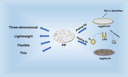
Lithium-sulfur batteries (LSBs) are highly advantageous for electric vehicles and portable electronics due to their high energy density. However, traditional metal foil current collectors pose many challenges in LSBs. On the anode side, the non-lithiophilic nature of copper foil leads to random lithium dendrite growth, increasing the risk of short circuits. On the cathode side, the electrochemical inertness and limited interfacial contact of aluminum foil cause slow polysulfide conversion under high sulfur loading, thus restricting cycling stability. Meanwhile, these heavy metal foils also reduce the overall energy density of the battery. Herein, we present an effective strategy to develop thin and lightweight 3D metallized current collectors (Ag@PEI-PP and Ni@PEI-PP) with functional interfaces for high-energy-density LSBs. These metallic collectors are made by cold-pressing polypropylene melt-blown fabrics and then applying metal coatings using a polymer-assisted deposition process. Compared to metal foil collectors, they possess an extremely light mass and excellent flexibility. The Ag@PEI-PP boosts the average Coulombic efficiency of lithium metal to 99.88% during cycling by enabling rapid lithium nucleation and uniform deposition. The Ni@PEI-PP maintains a high capacity retention rate of 99.88% per cycle over 200 cycles by speeding up the conversion of polysulfide and lithium sulfide. Based on the entire Li-S cell, including the current collector, active materials, and separator, the assembled LSB achieves high gravimetric (586 Wh kg−1) and volumetric (472 Wh L−1) energy densities. This metallic collector design provides an effective solution to improve the energy density and cycling stability of LSBs.
1 Introduction
The growing prevalence of electric vehicles and consumer electronics has significantly increased the industrial demand for rechargeable lithium batteries with high energy density and reliable safety. However, the currently dominant lithium-ion batteries on the market have reached the limits of their theoretical energy density [1-3]. In contrast, lithium-sulfur batteries (LSBs) have emerged as promising alternatives due to their exceptional theoretical energy density (2600 Wh kg−1), high specific capacity (1675 mAh g−1), and abundance of elemental sulfur [4]. Despite considerable progress, LSBs still face several key challenges in practical applications. First, the dendritic growth of the lithium metal anode and the shuttle effect of lithium polysulfides (Li2Sn, 4 ≤ n ≤ 8) easily cause irreversible lithium loss, rapid capacity decay, and safety risks. Second, the large volume changes of lithium metal and sulfur electrodes during cycling will lead to electrical contact separation between the electrodes and the current collectors [5-7]. Third, the use of heavy metal foils as current collectors significantly reduces the actual energy density of LSBs [8-10]. Therefore, it is crucial to develop an effective strategy that can simultaneously achieve high energy density, long cycling stability, and reliable safety for LSBs.
To enhance the actual energy density of batteries, significant efforts have been devoted to reducing the mass proportion of inactive components such as current collectors, conductive agents, and polymer binders [11-15]. However, functional agents and binders have a lower mass proportion compared to current collectors, which limits their contribution to energy density improvement. The traditional metal (copper and aluminum) foil current collector in a battery plays a vital role by efficiently collecting and conducting the electric current generated by the electrode reactions to the external circuit, thereby significantly influencing the energy density and cycling stability of the battery. However, the non-lithiophilic nature of copper foil easily leads to random lithium dendrite growth, increasing the risk of short circuits. In addition, the electrochemical inertness and limited interfacial contact of aluminum foil cause slow polysulfide conversion under high sulfur loading, thus restricting cycling stability. Compared to traditional metal foils, three-dimensional (3D) current collectors with interconnected porous structures have shown remarkable potential in alleviating the volume expansion of lithium and sulfur electrodes and promoting uniform ion distribution [16]. For example, conductive 3D current collectors, such as carbon fabric, graphene foam, carbon nanotube papers, and metal mesh, have been developed for stabilizing lithium and sulfur electrodes [17, 18]. Nevertheless, these 3D current collectors still suffer from poor affinity and inert interfaces with lithium metal and polysulfides, leading to sluggish redox kinetics and rapid capacity fading in LSBs at high-loading conditions [19-21]. Moreover, they typically account for 30%–80% of the electrode weight, which reduces the overall energy density of the actual LSBs [22-25]. Therefore, there is an urgent need to develop a lightweight conductive current collector to accelerate the kinetics of electrode reactions, thereby enhancing the cycling stability of high-energy-density LSBs.
Herein, we propose the unique design of thin and lightweight 3D metallized current collectors with functional interfaces for high-energy-density LSBs. These metallic current collectors are facilely prepared by cold-pressing polypropylene (PP) melt-blown fabrics and then applying metal coatings using a polymer-assisted deposition process. These metallized PP fabrics have much lighter mass density (~2.5 mg cm−2) than commercial metal foil current collectors but also exhibit exceptional mechanical flexibility and electrical conductivity. Importantly, silver-coated PP fabric (Ag@PEI-PP) can significantly improve the Coulombic efficiency of Li metal up to 99.88% during cycling by promoting rapid lithium nucleation and uniform deposition. Nickel-coated PP fabric (Ni@PEI-PP) enables the high capacity retention of 99.88% per cycle during 200 cycles by promoting rapid polysulfide and Li2S conversion. Consequently, the assembled LSB with a pair of metallic current collectors achieves high gravimetric (586 Wh kg−1) and volumetric (472 Wh L−1) energy densities based on the entire Li-S cell, including the current collector, active materials, and separator. The lightweight 3D current collectors hold great promise as alternatives to traditional metal foils and provide technical support for the practical application of future high-energy-density LSBs.
2 Results and Discussion
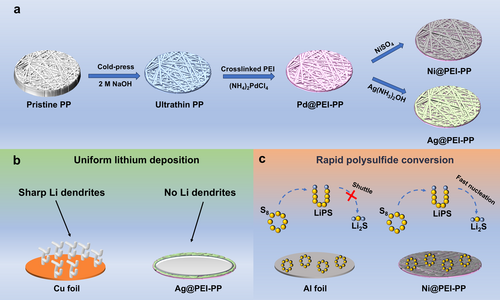
The preparation process of lightweight metal-coated current collectors is illustrated in Figure 1a. Initially, PP fabric undergoes roller pressing to obtain the cold-pressed PP with a thickness of about 35 μm, while preserving its structural integrity (Figure S1). Subsequently, the cold-pressed PP fabric is treated with alkali activation, resulting in oxygen-containing PP that is rich in hydrophilic groups. This modified fabric is then soaked in polyethyleneimine (PEI) solution, containing a large number of amino groups, which can effectively chelate with metal ions. To ensure robust attachment, glutaraldehyde is employed to initiate polymerization of the hydrophilic groups and PEI, thereby firmly bonding PEI to the cold-pressed PP fabric. Following this, the PEI-functionalized PP (PEI-PP) is immersed in the (NH4)2PdCl4 aqueous solution to load the catalyst [PdCl4]2− [26]. The final step involves electroless deposition (ELD), where the PEI-PP is immersed in a Ni bath to form nickel-coated PEI-PP (Ni@PEI-PP). The silver-coated PEI-PP (Ag@PEI-PP) is prepared in a Cu bath and subsequently transferred to an Ag bath. Compared with the inherent lithiophobic properties and uneven surface of Cu foil, Ag coating on the Ag@PEI-PP significantly reduces the nucleation overpotential and energy barrier, thereby promoting uniform plating of Li metal. Meanwhile, the 3D structure can effectively alleviate the volume expansion of Li metal during the plating/stripping process. Therefore, the synergistic effect of the Ag coating and 3D structure effectively regulates the deposition behavior of Li metal and inhibits the formation of lithium dendrites (Figure 1b). In addition, when compared with Al foil, the 3D structure of Ni@PEI-PP offers more nucleation sites of lithium sulfide and enhances the redox kinetics of polysulfide and lithium sulfide in LSBs (Figure 1c).
The surface morphologies and microstructures of the Ni@PEI-PP and Ag@PEI-PP were characterized by scanning electron microscopy (SEM). Figure 2a,b show the SEM images of the pristine PP and cold-pressed PP. It can be seen that the PP fabric becomes flat and dense after cold pressing (Figure S1). In Figure S2, the colors of Ni@PEI-PP and Ag@PEI-PP exhibit noticeable changes compared with the pristine and cold-pressed PP in Figure S1. Simultaneously, the SEM images of Ni@PEI-PP in Figure 2c show that a thin layer of Ni is uniformly attached to the fibers. Figure 2d exhibits that the total thickness of the fabricated Ni@PEI-PP is around 50 μm. Figure S3a–e presents the SEM image and the corresponding energy dispersive spectroscopy (EDS) mappings of Ni@PEI-PP, demonstrating a homogeneous distribution of C, Ni, N, and O across the fibers. High-resolution SEM images (Figure S3f,g) further confirm that the size of Ni particles is around 650 nm. Similarly, Figure 2e,f displays the surface and cross-section SEM images of Ag@PEI-PP, revealing that Ag is in the form of nanoparticles. Meanwhile, the thickness of the Ag@PEI-PP is about 50 μm. Figure S4a–f further illustrates the SEM image and EDS mappings for Ag@PEI-PP, where the Cu, Ag, C, N, and O elements are anchored on the fibers evenly. Notably, high-resolution SEM images (Figure S4g,h) demonstrate that the Ag nanoparticles exhibit a well-defined size of 500 nm. The detailed element contents of the prepared Ni@PEI-PP and Ag@PEI-PP are also provided in Tables S1 and S2. In addition, the Cu@PEI-PP was fabricated without transferring to the Ag bath solution. The photograph and SEM images of Cu@PEI-PP in Figure S5 confirm the successful coating of Cu on the fibers. Figure 2g shows the XRD patterns of pristine PP and the above three prepared flexible metal-coated fabrics. It can be observed that the Ag@PEI-PP, Ni@PEI-PP, and Cu@PEI-PP comprise the diffraction peaks corresponding to Ag, Ni, and Cu, respectively, relative to the pristine PP fiber mat, thereby representing that the metal layers have been anchored on the fibers [27-29]. Figure S6a–c exhibits the XPS survey spectra of Ni@PEI-PP, Ag@PEI-PP, and Cu@PEI-PP with the signals of Ni, Ag, and Cu, respectively. Figures 2h,i and S6d show high-resolution XPS spectra of Ni 2p (865.2 eV and 874.1 eV), Ag 3d (368.5 eV and 374.5 eV), and Cu 2p (932.6 eV and 952.4 eV), proving the formation of corresponding metal layers [30-32].
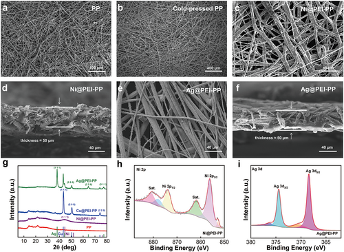
The metallized current collectors have a light mass density but also exhibit exceptional mechanical flexibility and electrical conductivity. The achieved Ni@PEI-PP and Ag@PEI-PP possess the advantages of low areal mass density (2.5–3.0 mg cm−2), electrical resistance (1.0–3.0 Ω cm−2), and volumetric densities (0.5–0.7 g cm−3) (Figure S7). Despite the thickness (50 μm) of Ag@PEI-PP and Ni@PEI-PP being higher than those of Al foil (15 μm) and Cu foil (10 μm), they are still much thinner than state-of-the-art 3D current collectors. The tensile strain of Ag@PEI-PP and Ni@PEI-PP can reach 2.7% and 2.3%, respectively, outperforming 1.9% for Cu foil and 1.1% for Al foil (Figure S8a). Moreover, when bent 100,000 times at a flexing radius of 5 mm, the resistances of Ni@PEI-PP (from 3.60 Ω cm−2 to 4.75 Ω cm−2) and Ag@PEI-PP (from 0.80 Ω cm−2 to 1.73 Ω cm−2) exhibit negligible change (Figure S8b,c), suggesting their exceptional mechanical stability. Additionally, the samples underwent a swelling test by being immersed in the electrolyte of 1 M LiTFSI in 1,3-dioxolane (DOL) and 1,2-dimethoxyethane (DME) (v/v, 1:1) with 2 wt.% LiNO3 additive for 2 months (Figure S9). Throughout this period, both Ag@PEI-PP and Ni@PEI-PP maintained their thickness with no significant variation whether at room temperature (25°C) or elevated temperature (70°C). This result highlights the remarkable stability of the prepared metal-coated PP fabrics in the electrolyte environment. Consequently, the Ni@PEI-PP and Ag@PEI-PP meet the requirements of being used as flexible current collectors, offering a promising alternative for energy storage devices [33-35].
To confirm the feasibility of current collectors, the fabricated Ni@PEI-PP and Ag@PEI-PP were applied to lithium metal batteries. The Ag@PEI-PP//Li and Cu foil//Li cells were assembled to investigate the nucleation behavior of Li metal on the current collector during the plating process. As illustrated in Figure 3a, the initial plating profiles of Ag@PEI-PP//Li and Cu foil//Li at the current density of 0.1 mA cm−2 reveal that the Ag@PEI-PP//Li displays an almost zero tip voltage and a low mass-transfer voltage of 13.3 mV. Therefore, the nucleation overpotential of Li deposition on the Ag@PEI-PP current collector is only 13.3 mV. During the plating process, the Li+ first reacts with Ag to form a Li-Ag alloy, followed by reduction and subsequent deposition of Li metal [36]. By contrast, the Cu foil//Li battery shows much higher values for tip voltage (70.9 mV), mass-transfer voltage (26.3 mV), and nucleation overpotential (44.6 mV). As the current density increases to 1 mA cm−2 in Figure 3b, the nucleation overpotential of Ag@PEI-PP//Li (48.7 mV) is still lower than that for Cu foil//Li (98.3 mV), which confirms that the lithiophilic Ag nanoparticles attached to the fibers effectively reduce the nucleation overpotential and energy barrier, facilitating uniform deposition of Li metal. Meanwhile, the Coulombic efficiency (CE) of Ag@PEI-PP//Li and Cu foil//Li during repeated plating/stripping of Li metal is presented in Figure 3c,d. The average CE of Ag@PEI-PP//Li is 99.88%, surpassing the CE of Cu foil//Li (99.26%). The higher average CE illustrates the capability of the Ag@PEI-PP current collector to suppress side reactions during Li plating/stripping processes, thereby enhancing the overall performance of lithium batteries [37, 38].
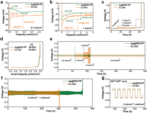
To further investigate the long-term cycling stability and rate performance, symmetric batteries were assembled using Li metal-deposited Ag@PEI-PP and Cu foil, respectively, with an electrode capacity of 6 mAh cm−2. Figure 3e depicts the rate properties of these symmetric batteries at varying current densities of 0.5, 1, 2, 5, and 0.5 mA cm−2. It is shown that the overpotential of the symmetric battery with Cu foil is much higher than that with Ag@PEI-PP, further demonstrating that the Ag@PEI-PP contributes to preventing dendritic growth under various current densities [39, 40]. Furthermore, the long cycling test results presented in Figures 3f,g and S10 illustrate the superior electrochemical performance with Ag@PEI-PP. Under the current density of 1 mA cm−2 and Li plating/stripping capacity of 1 mAh cm−2, both of the symmetric batteries surpass 600 h (approximately 300 cycles) in Figure S10a. However, the overpotentials of lithium metal plating/stripping during the cycling process of Ag@PEI-PP-based symmetric batteries are lower than those with Cu foil in Figure S10b,c. Meanwhile, when operated under the areal capacity of 1 mAh cm−2 and current density of 2 mA cm−2, the Ag@PEI-PP-based battery demonstrates an extended cycle life of 430 h, outperforming the Cu foil-based cell with 300 h, as shown in Figure 3f. After 200 cycles, the overpotentials of the symmetric battery with Ag@PEI-PP and Cu foil are 26.3 and 33.1 mV, respectively (Figure 3g). Moreover, at an increased plating/stripping capacity of 2 mAh cm−2 under the current density of 1 mA cm−2, the assembled symmetric battery with Cu foil fails after 185 h, whereas the Ag@PEI-PP-based battery lasts 675 h in Figure S10d. In brief, the symmetric battery incorporating Ag@PEI-PP current collector takes advantage of lithiophilic interfaces of Ag nanoparticles and porous structures of 3D fabrics, showing minimal voltage fluctuation and prolonged plating/stripping cycles. On the contrary, the Cu foil-based symmetric battery suffers from continuous voltage fluctuation and limited cycling life, attributed to the rough surface of Cu foil (Figure S11), resulting in uneven lithium dendrites [41-43].
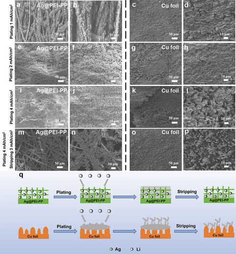
To gain a deeper insight into the microstructural changes of different current collectors after lithium plating/stripping, Figure 4a–p shows the top-view SEM images of Ag@PEI-PP and Cu foil after Li metal deposition at various areal capacities of 1, 2, and 4 mAh cm−2. At a relatively low plating areal capacity of 1 mAh cm−2, the fiber structure of Ag@PEI-PP remains visible after Li metal deposition. The Li metal is uniformly deposited on the surface of each metallic fiber. When the plating capacity of Li metal is increased to 4 mAh cm−2, the Li deposition layer on Ag@PEI-PP remains flat and homogeneous, which is in stark contrast to the dendritic deposition on Cu foil (Figure 4i–l). Impressively, after stripping of 3 mAh cm−2, the fibers of Ag@PEI-PP still retain a uniform deposition layer of Li metal. In contrast, after stripping of 3 mAh cm−2, the Cu foil surface retains a large number of irregular Li bumps (Figure 4m–p). Therefore, these characterizations suggest that the 3D structure of Ag@PEI-PP may effectively reduce the local current density of Li metal during the deposition/stripping process, facilitating uniform Li plating. At the same time, it can accommodate and mitigate the volume changes during Li deposition, effectively inhibiting the growth of lithium dendrites. The lithiophilic Ag-modified layer works in synergy with the 3D structure, regulating the deposition behavior of Li metal. In contrast, due to its inherent lithiophobic properties and rough surface, the Cu foil undergoes uneven Li nucleation during deposition, leading to the vigorous growth of lithium dendrites, as depicted in Figure 4q.
In addition, the Ni@PEI-PP was also employed as a current collector in the sulfur cathode to evaluate its impact on the conversion kinetics of lithium polysulfide and lithium sulfide. Figure 5a,b exhibit CV curves of the LSBs with Ni@PEI-PP and Al foil current collectors at the scan rate of 0.05 mV s−1, respectively. Both sets of CV curves feature two distinct pairs of redox peaks. The reduction peak at approximately 2.3 V (R1) is associated with the transformation of sulfur into long-chain polysulfides (LiPS, Li2S4-8). Meanwhile, the reduction peak around 2.0 V (R2) corresponds to the further conversion of LiPS into Li2S2/Li2S. During the reverse scan, the oxidation peak near 2.3 V (O1) represents the process of Li2S2/Li2S converting back into LiPS, and the oxidation peak at about 2.4 V (O2) signifies the conversion of LiPS into sulfur [44-46]. Compared to Al foil, the CV cycles of LSBs prepared with Ni@PEI-PP current collector almost overlap, indicating excellent reversibility. The overpotentials between the reduction peaks (R1) and the oxidation peak (O1), defined as ΔV, are lower for the Ni@PEI-PP-based cells, indicating enhanced redox kinetics and sulfur utilization during the solid–liquid and liquid–solid phase transitions [47, 48]. To further explore the effect of Ni@PEI-PP current collector on LiPS, the symmetric cells of Ni@PEI-PP//Ni@PEI-PP and Al foil//Al foil using 0.2 M Li2S6 as electrolyte were assembled and tested (Figure 5c). At a scan rate of 20 mV s−1, the symmetric cell based on Ni@PEI-PP exhibits distinct oxidation and reduction peaks at 0.7 and −0.7 V, respectively. The oxidation peak is attributed to the conversion process of Li2S6 to sulfur, while the reduction peak corresponds to the transformation of sulfur to LiPS [49]. In contrast, no significant peaks are observed for the Al foil-based battery, illustrating that Ni@PEI-PP can further enhance the redox kinetics of sulfur. The nucleation and deposition of Li2S are considered an indicator of electrochemical kinetics [50, 51]. To further demonstrate the superiority of Ni@PEI-PP in the process of Li2S conversion, Figure 5d,e present the potentiostatic discharge curves at 2.05 V for the electrodes based on Ni@PEI-PP and Al foil. The Li2S deposition capacity reaches 180.20 mAh gsul−1 with Ni@PEI-PP, significantly higher than the 53.26 mAh gsul−1 achieved with Al foil. This is attributed to the 3D structure of Ni@PEI-PP, which provides more nucleation sites and facilitates the growth of deposits. At the same time, Ni metal can also promote the conversion of polysulfides to Li2S [52]. These results further prove that Ni@PEI-PP significantly boosts the redox kinetics in LSBs when used as a current collector.
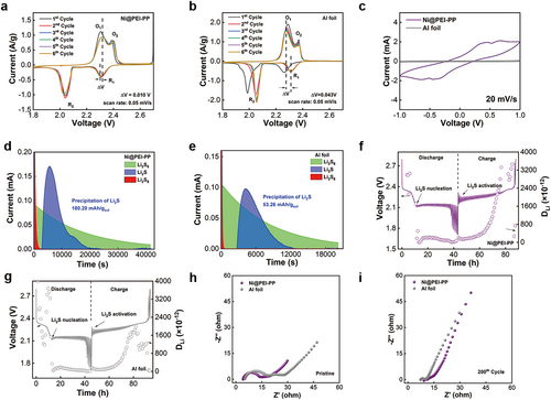
To determine the Li+ diffusion coefficient (DLi+) of the current collector in the sulfur cathode, galvanostatic intermittent titration technique (GITT) tests were conducted (Figure 5f,j) [53]. The DLi+ value for the Ni@PEI-PP current collector is determined to be 1.3 × 10⁻¹⁰ cm2 s−1, which is much higher than that with the Al foil current collector (9.8 × 10⁻¹¹ cm2 s−1), revealing the improved Li+ diffusion kinetics. To obtain a deeper understanding of the interfacial characteristics of LSBs with different current collectors, the electrochemical impedance spectroscopy (EIS) tests were performed at the pristine state and after 200 cycles at the rate of 1 C, as depicted in Figure 5h,i. The Nyquist plots consist of two approximate semicircles followed by a sloping line, which sequentially correspond to contact resistance (Rs) in the high-frequency region, the charge transfer resistance (Rct), and the resistance formed by non-conductive materials, specifically Li2S/Li2S2 (RLi-s) [54]. The sloping line represents the resistance associated with the diffusion process. The equivalent circuit of the Nyquist plots is shown in Figure S12a. According to the results of the equivalent circuit fitting presented in Figure S12b,c, and Tables S3 and S4, the Rct of Ni@PEI-PP is lower than that of Al foil before and after cycling, indicating that Ni@PEI-PP reduces the reaction kinetic barrier in LSBs. However, the Rs and RLi-S for the Ni@PEI-PP are higher compared to Al foil after cycling, which is attributed to the deposition of Li2S passivation layers within the 3D structure, introducing additional interfacial resistance [55].
To further investigate the electrochemical performance of the sulfur cathode with Ni@PEI-PP current collector, long-term cycling and rate measurements were carried out. Figure 6a shows the long-term cycling stability of the sulfur cathode with a sulfur loading of 1.59 mg cm−2 using Ni@PEI-PP and Al foil as current collectors at 0.5 C after three cycles for activation at 0.1 C. The LSBs with Ni@PEI-PP current collector exhibit an initial discharge capacity of 926 mAh g−1, which remains at 689 mAh g−1 after 200 cycles with a decay rate of 0.128% per cycle. In contrast, the cell with an Al foil current collector delivers an initial discharge capacity of 823 mAh g−1, which decreases to 471 mAh g−1 after 200 cycles, corresponding to a decay rate of 0.214% per cycle. These results demonstrate that the Ni@PEI-PP current collector contributes to enhancing the cycling stability of the sulfur cathode. As observed from the charge/discharge profiles in Figure 6b,c, the LSBs with Ni@PEI-PP current collector exhibit a relatively higher capacity and lower voltage polarization, which indicates that the Ni@PEI-PP current collector mitigates the dissolution and shuttle effect of polysulfides [56]. In addition, Figure 6d displays the rate performance of the sulfur cathode with Ni@PEI-PP and Al foil current collectors. It should be pointed out that the discharge capacities of the cells based on Ni@PEI-PP are 988, 838, 737, 669, 612, and 576 mAh g−1 at 0.1 C, 0.2 C, 0.5 C, 1 C, 2 C, and 3 C, which are much higher than those with Al foil under the same rates. The charge–discharge curves at various rates (Figure S13) further confirm that the Ni@PEI-PP-based battery maintains a lower polarization voltage (0.118 V) compared with that of Al foil (0.141 V).
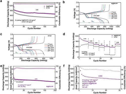
Enhancing the loading of active sulfur in the cathode is crucial for improving the actual energy density of LSBs. As a 3D current collector, Ni@PEI-PP offers considerable advantages over 2D Al foil in fabricating high-loading electrodes, owing to its larger surface area, increased number of active sites, and stronger mechanical support. Figure 6e illustrates the cycling performance of LSBs employing Ni@PEI-PP and Al foil current collectors under high-loading-sulfur conditions. The top-view and cross-sectional SEM analysis indicates the cathode materials (sulfur, Ketjen Black 600, and Super P) uniformly penetrated the porous framework of Ni@PEI-PP (Figure S14). After the initial three cycles' activation at 0.1 C, the cells underwent long-term cycling at 0.2 C. Even with a substantial sulfur loading of 5.47 mg cm−2, Ni@PEI-PP-based battery achieves an initial areal capacity of 4.05 mAh cm−2. Remarkably, after 100 and 200 cycles, the areal capacity remains at 3.53 and 3.00 mAh cm−2, with a high capacity retention rate of 99.88% per cycle. To explore the practical application of Ni@PEI-PP and Ag@PEI-PP, full LSBs were assembled using Ni@PEI-PP loaded with sulfur/carbon composite as cathode (sulfur loading of 7.07 mg cm−2) and Ag@PEI-PP deposited with a limited 200% excess of Li metal as anode, maintaining an N/P ratio of 3:1. As shown in Figure 6f, the assembled full LSB with metallic current collectors and high-loading active materials shows an initial areal capacity of 6.44 mAh cm−2, corresponding to high gravimetric (586 Wh kg−1) and volumetric (472 Wh L−1) energy densities (Table S5) based on the entire battery. The lightweight metallized current collector design provides technical support for the practical application of future high-energy-density batteries.
3 Conclusions
In summary, our work reports an effective strategy to develop two types of 3D metallized melt-blown PP fabrics as thin and lightweight current collectors for high-energy-density LSBs. These metallized PP melt-blown fabrics possess low mass density, high electronic conductivity, and superior mechanical properties. The Ag@PEI-PP collector with lithiophilic interfaces boosts the average Coulombic efficiency of lithium metal to 99.88% during cycling by regulating the deposition behavior of Li metal and suppressing lithium dendrite growth. Furthermore, the Ni@PEI-PP collector with high catalytic interfaces accelerates the conversion kinetics of polysulfide and lithium sulfide, inhibiting the shuttle effect of the sulfur cathode. The Ni@PEI-PP collector maintains a high capacity retention rate of 99.88% per cycle over 200 cycles for the sulfur cathode. Importantly, the full LSBs constructed with metallic current collectors, high-loading electrode materials, and separators achieve high gravimetric (586 Wh kg−1) and volumetric (472 Wh L−1) energy densities. Consequently, the lightweight current collectors of 3D metallized fabrics are also applicable to constructing other batteries (e.g., sodium, potassium, and zinc metal batteries, etc.) to enhance their energy density and cycling stability.
4 Experimental Section
4.1 Raw Materials
Polypropylene (PP) melt-blown fabric was purchased from Keimei Plastifizierung Technik (Yantai) Co. Ltd. CuSO4·5H2O, KNaC4H4O6·4H2O, NaOH, HCl, Li2S, tetraglyme, bis(trifluoromethane) sulfonimide lithium salt (LiTFSI), polyethyleneimine (PEI), glutaraldehyde, and methanol were obtained from Shanghai Meril Biochemical Technology Co. Ltd. (NH4)2PdCl4 and formaldehyde solution were provided by Shanghai Macklin Biochemical Co. Ltd. AgNO3 was purchased from Tianjin Damao Chemical Reagent Co. Ltd. NiSO4 was purchased from Fuchen (Tianjin) Chemical Reagents Co. Ltd. Sodium citrate, NaH2PO2, and dimethylamine borane (DMAB) were purchased from Aladdin Reagent Co. Ltd. NH3·H2O (25 wt.%) was obtained from Tianjin Baishi Chemical Co. Ltd. Sublimed sulfur (≥ 99.5%) was purchased from Guangzhou Chemical Reagent Factory. The Ketjen Black (ECP-600JD) and conductive carbon black (Super P) were purchased from Guangdong Zhuguang New Energy Technology Co. Ltd. Soybean powder (protein content ≥ 50%) was obtained from Shandong Wonderful Industrial Group Co. Ltd. Aluminum foil, copper foil, CR2025 coin cell, and Celgard 2400 separators were purchased from Guangdong Canrd New Energy Technology Co. Ltd. The electrolyte was purchased from Duoduo Reagent Factory.
4.2 Materials Synthesis
Preparation of Ni@PEI-PP and Ag@PEI-PP: The PP melt-blown fabric was first immersed in 2 M NaOH solution at 70°C for 2 h to introduce oxygen-containing groups on its surface. Subsequently, the oxygen-containing PP was soaked in 4 wt.% PEI solution (solvent: methanol) at 35°C for 5 min. After thorough rinsing, it was then immersed in 4 wt.% glutaraldehyde aqueous solution at 35°C for 1 h to facilitate the cross-linking reaction of PEI with the oxygen-containing groups, yielding PEI-PP. After that, the PEI-PP was placed in the 5 × 10⁻³ M (NH4)2PdCl4 aqueous solution at room temperature for 2 min to obtain Pd@PEI-PP, which was then subjected to electroless deposition (ELD) in a Ni bath for 30 min at room temperature, resulting in Ni@PEI-PP. Meanwhile, Pd@PEI-PP was immersed in a Cu bath at 40°C for 2 min and then transferred to the Ag plating solution to produce Ag@PEI-PP under ice bath conditions. The ELD of Ni was performed in the mixture of solutions A and B. Solution A was prepared by dissolving 2 g NiSO4, 3.3 g sodium citrate, and 1.4 g NaH2PO2 in 100 mL DI water. Solution B is a DMAB aqueous solution with a concentration of 3 g L−1. NH3·H2O was used to adjust the pH of the Ni plating bath to neutral. The ELD of Cu was prepared by mixing solution A and solution B with a volume ratio of 1:1. Solution A was obtained by dissolving 1.3 g CuSO4·5H2O, 2.9 g KNaC4H4O6·4H2O, and 1.2 g NaOH in 100 mL DI water. Solution B was an HCHO (9.5 mL/L) aqueous solution. The ELD of Ag was formed by dissolving 0.1 g AgNO3 in 100 mL DI water, and then adding 28 wt.% NH3·H2O dropwise. White precipitate initially appeared but disappeared completely with the continued introduction of NH3·H2O. Subsequently, 0.5 g KNaC4H4O6·4H2O was added to obtain the Ag bath solution.
Preparation of Sulfur Cathodes: The sulfur/carbon composite was prepared using a melt-diffusion strategy. Sulfur powder, Ketjen black 600, and super P were first mixed with a mass ratio of 4:1:1, followed by heating in a vacuum oven at 160°C for 12 h. The sulfur can be molten and diffused into the carbon matrix to obtain a sulfur/carbon composite. The prepared sulfur/carbon composite and soybean protein isolate (SPI) binder (Preparation method in Supporting Information) were mixed at a mass ratio of 9:1 to form a homogeneous slurry with the addition of water. Subsequently, the mixture was uniformly coated onto the Ni@PEI-PP substrate, which was then dried at room temperature for 8 h to evaporate the solvent, followed by vacuum drying at 80°C for 12 h to ensure complete solvent removal and enhance structural stability. Finally, the sulfur cathodes were punched into circular sheets with a diameter of 12 mm.
Preparation of Lithium Anodes: First, the Ag@PEI-PP was cut into round plates with a diameter of 12 mm. CR2025 coin cells were assembled with Ag@PEI-PP, lithium foil, Celgard 2400 membrane, as well as 1 M LiTFSI dissolved in the mixture of DOL and DME (v/v, 1:1) with 2 wt.% LiNO3 additive as the working electrode, counter electrode, separator, as well as electrolyte, respectively. The cell was initially subjected to charge/discharge at 0.1 mA/cm2 for two cycles. Subsequently, lithium plating was performed during the discharging process at the specific current density and areal capacity.
4.3 Devices Preparation
Preparation of Ni@PEI-PP Symmetric Cells: Super P, Ketjen black, and Soybean protein isolate (SPI) binder with a mass ratio of 4.5:4.5:1 were first mixed into a cathode composite slurry and coated on the Ni@PEI-PP current collectors, which were dried at 60°C for 12 h in the vacuum oven. In addition, S and Li2S with a mass ratio of 5:1 were dissolved in the DOL/DME (v/v, 1:1) mixture and heated at 60°C for 24 h to obtain Li2S6 electrolyte. For the preparation of symmetric cells, two pieces of Ni@PEI-PP coated with super P, Ketjen black, and SPI binder, Celgard 2400 separator, as well as the Li2S6 electrolyte, were assembled in the glove box.
Fabrication of LSBs: For the Li-S half and full cells, the sulfur/carbon composite coated Ni@PEI-PP, Celgard 2400, and 1 M LiTFSI in DOL/DME (v/v, 1:1) with 2 wt.% LiNO3 additive was used as the cathode, separator, and electrolyte, respectively. The mass ratio of electrolyte dosage and active sulfur in the Li-S half cells was 25 μL mg−1. It is worth noting that commercial Li metal was applied as an anode in Li-S half cells, while the lithium-plated Ag@PEI-PP anode was used in full LSBs with a limited N/P ratio of 3:1.
4.4 Characterizations
The microstructure and morphology of materials were characterized by field-emission scanning electron microscopy (SEM, EVO MA 15). X-ray diffractometer (XRD) analyses were conducted on XD-2X/M4600 equipment with Cu Kα radiation (λ = 1.5418 Å). The surface chemical components of the Ni@PEI-PP, Cu@PEI-PP, and Ag@PEI-PP were obtained by x-ray photoelectron spectroscopy (XPS, Thermo Scientific K-Alpha). The mechanical performance of various current collectors was tested with the UTM4204 equipment system.
4.5 Electrochemical Measurements
The long cycling and rate tests of lithium-deposited Ag@PEI-PP symmetric cells, charge–discharge curves, and galvanostatic intermittent titration technique (GITT) of LSBs were carried out on Neware battery systems (CT-ZWJ-4S-T-1U). The cyclic voltammetry (CV) curves and electrochemical impedance spectroscopy (EIS) in the frequency range from 100 kHz to 0.01 Hz of the assembled LSBs were measured using the CHI 660 electrochemical workstation.
For the nucleation experiment of Li2S, the slurry of Super P and SPI with the mass ratio of 9:1 coated on Ni@PEI-PP electrode, lithium foil, and Celgard 2400 served as cathode, anode, and separator, respectively. The mass loading of Super P on the Ni@PEI-PP current collector was 0.2 mg cm−2; 0.3 M Li2S8 and 1.0 M LiTFSI in tetraglyme solution were used as catholytes. The anolyte was composed of 1.0 M LiTFSI in a tetraglyme solution without Li2S8. The dosage of catholyte and anolyte was 20 μL. For the Li2S nucleation measurement, the constructed cells were initially discharged galvanostatically to 2.12 V, and subsequently discharged to 2.05 V, using a cut-off current of 0.01 mA to initiate and promote the nucleation and growth of Li2S.
Author Contributions
Haomin Zhao: writing – original draft, visualization, data analysis. Yuting Wang: data analysis. Yuanyuan Jiang: data analysis. Zhe Luo: data analysis. Dong Chen: data analysis. Rui Jia: writing, data analysis. Yu Yang: supervision, resources, conceptualization. Jian Chang: writing, editing, supervision, resources, conceptualization.
Acknowledgments
The authors gratefully acknowledge financial support from Shenzhen Science and Technology Program (JCYJ20220818100218040), National Natural Science Foundation of China (22109066 and 22371116), and Natural Science Foundation of Guangdong Province (2024A1515010704). This work was also supported by the Guangdong Provincial Key Laboratory of Energy Materials for Electric Power (2018B030322001) and Research Team on Solar Metamaterials (2024KCXTD048).
Conflicts of Interest
The authors declare no conflicts of interest.


