Challenges in Laboratory Catalytic Testing for Ammonia Decomposition under Industrially Relevant Conditions
Abstract
Fundamental studies on screening catalyst materials with potential for application in large-scale industrial ammonia reforming processes pose a significant challenge. Not only are the requirements on the catalyst itself critical, but the industrially relevant reaction conditions impose very high demands on the reactor materials, especially in terms of temperature and corrosion resistance, as well as the general layout of a suitable test rig on laboratory scale. Here, an automatized setup for high-throughput studies on heterogeneous catalysts in ammonia decomposition, with a strong focus on reactor material selection and the capability of the setup to generate highly reproducible and thus comparable results, is described. With this approach, it is ultimately possible to contribute to identify possible catalyst materials applicable in industrial ammonia reforming.
1 Introduction
As ammonia is one of the most promising hydrogen and energy carriers for a potential hydrogen-based renewable energy economy, ammonia decomposition has become recently an intensively studied reaction.[1] Due to the intermittent and location-dependent supply of major renewable energies (e.g., sun and wind), a suitable system for the storage and long-range transport of energy on the global scale is required.[2] The most frequently discussed system is the storage of energy in the form of hydrogen using water electrolysis.[3] If required, the energy can be retrieved back from hydrogen by the use of fuel cells, but hydrogen itself is not well suited for efficient storage and long-distance transport, for example, overseas, due to its low density and low boiling point. The direct storage and transport of hydrogen would require either high storage volumes or high energy consumption for compression or condensation.3 Therefore, current research aims at the storage of hydrogen in the form of a hydrogen carrier.
As a chemical hydrogen storage medium, ammonia has several main advantages: It has a relatively high energy density per volume and per mass compared to other potential hydrogen carriers and the ammonia synthesis and decomposition routes are carbon free. Furthermore, ammonia synthesis from hydrogen (Haber–Bosch process) and ammonia storage and transport are already performed on an industrial scale for over 100 years.[4] Thus, ammonia synthesis, transport, and storage are already highly optimized. The major missing part for the usage of ammonia as an efficient storage molecule is an optimized catalyst suitable for ammonia decomposition in an industrial large-scale process. This requires a catalyst system for ammonia decomposition, which works under industrially significant conditions, and a lot of research is conducted on potential catalyst materials.1 Consequently, in order to obtain meaningful results for adaptation in a larger-scale process, potential catalysts need to be tested on a laboratory scale under industrially relevant conditions with a precise control over all parameters. Performing ammonia decomposition with pure ammonia and at full conversion into hydrogen and nitrogen is required for an efficient process. At atmospheric pressure, this is only possible at temperatures above 400 °C due to thermodynamic limitations.1 For some industrial chemical processes, which require hydrogen at higher pressures, it would even be advantageous to decompose ammonia at elevated pressures. This would in turn shift the required temperature to even higher values.1 With the high corrosive potential of pure ammonia (especially at elevated temperatures), these conditions induce high demands on corrosion-resistant components of a potential ammonia decomposition setup on laboratory scale as well as on industrial scale. Additionally, the well-known phenomenon of hydrogen embrittlement needs to be considered when choosing materials for the reactor construction.[5] While especially martensitic steels are highly susceptible to hydrogen-induced corrosion, embrittlement has also been reported for ferritic and to some extent even for austenitic steels.[6]
To obtain meaningful results on a laboratory scale, further requirements for a potential test setup have to be considered. The setup and especially the reactor need to be inert under ammonia decomposition conditions to ensure reliable information on the catalytic activity of a sample as well as the comparability of its performance to other potential catalytic systems or other studies. At the same time, the reactor requires a well-defined temperature profile and optimized heat conductivity, as ammonia decomposition is strongly endothermic and can cause significant cold spots at high conversions. Otherwise, the obtained results might lead to misleading temperature–activity relationships. Furthermore, it would be beneficial if the reactor is resistant to structural failure and highly gas tight. This is also required for the retrieval of a sample after testing under inert conditions. Ammonia decomposition proceeds under highly reductive conditions and the true nature of the active phase of a spent catalyst might be affected by structural changes if the sample is exposed to air. This would severely limit the deeper understanding of a catalyst system, and therefore also its further optimization.
2 Experimental Section
2.1 Flow Setup
For a reproducible testing of heterogeneous catalysts in ammonia decomposition, an automatized flow setup was constructed, consisting of four identical sections, which could be operated independently. Figure 1 depicts the representative flow diagram of a single, while the process flow diagram of the complete setup as well as a photograph are shown in the Supporting Information (Figure S1 and S2). Each section included a gas supply for H2, N2, Ar and gaseous NH3 (gas purity: 5.0), as well as an additional gas line which can be used for, for example, calibration gases or probe molecules. At the inlet of the setup all gases were stripped of oxygen and moisture down to the <ppbV level using activated metal-based adsorption filters (MicroTorr GateKeeper GPUS), which were found to be highly effective in ammonia synthesis with extremely oxygen-sensitive Fe-based catalysts.[7] The gas lines were equipped with manual line pressure regulators for a steady inlet gas pressure set to 4 bar, consequently avoiding potential condensation of NH3 in the respective supply line, and could be individually sealed by solenoid valves. Mass flow controllers (MFC, Bronkhorst EL-FLOW Select F-201CV) were used to set the volume flow parameters. Redundant membrane valves secured each gas supply line by shutting down the gas flow in case of a failure and isolated the corresponding MFC from the rest of the setup. To prevent damage to the MFC regulating the NH3 flow, a bypass line from the N2 supply was installed to be able to flush the ammonia line with dry inert gas after each use and to keep it under N2 atmosphere when not in use. The precise mixing of gas streams into the central upstream gas line was achieved via practically dead-volume free 4- and 6-port VICI Valco valves (Valco Instruments Co. Inc./VICI AG). Check valves were installed at the outlet of the supply lines to suppress any back flow. The fixed bed tubular flow reactor was heated in a single-stage electric furnace (HTM Reetz Laborklappofen Mini-LK 1050-20-200). Controlling and measuring temperature was accessible via type-N thermocouples placed in different positions of the system. All tubes and steel components potentially exposed to NH3 were coated with SilcoNert-2000 (amorphous silicon, 100–500 nm, SilcoTek) wherever feasible to prevent any adsorption and corrosion of the steel. The downstream section was fully encased in a trace heating line and a hotbox kept at 50 °C to ensure a constant temperature and prevent any condensation of products or moisture traces. The outlet of the setup was not constricted, leading to atmospheric pressure in the downstream section. Upstream pressure during ammonia decomposition experiments was slightly increased due to catalyst bed packing, with a maximum pressure drop of ≈0.3 bar under the standard reaction conditions. Online product gas analysis was realized via IR detectors for quantification of NH3 and H2O as well as a thermal conductivity detector for H2 (Emerson XStream XEGP). To account for a potential pressure drop as well as register possible critical overpressures, piezoresistive pressure transmitters were installed in front of and behind the tubular reactor (PA35 X HTT, Keller AG für Druckmesstechnik). Furthermore, the setup was equipped with sensors for temperature (multiple type K thermocouples) and dangerous gases (GMC 8022, ExDetector HC 150, Gasmonitor NH3-200, Bieler + Lang GmbH), which were integrated in the alarm matrix and triggered the required shutdown of corresponding sections in an emergency situation to put the setup in a safe state. The automatic operation and surveillance of the flow setup and processing of user input were realized centrally via a cRiO and a LabVIEW interface (National Instruments).
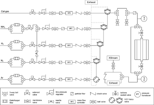
The tubular flow reactor was built from a reactor tube with a 1/4″ or 3/8″ outer diameter and a length of ≈300 mm, oriented vertically in the electrical furnace. Bellows-sealed valves with a very low leak rate in the upstream and downstream section allowed the extraction of the reactor under inert conditions. Optionally, an immersion tube could be placed in the center of the reactor tube to accommodate a type-N thermocouple used for measuring the temperature in various positions of the reactor tube, for example, the catalyst bed, without coming into contact with the catalyst itself, preventing potential contribution to the ammonia decomposition activity by the thermocouple itself (Figure 2). Before conducting an experiment, any leaks in the corresponding segment were excluded by flushing with 100% H2 and subsequently testing the reactor and every fresh connection with a leak detector for flammable gases (minimum sensitivity 5 ppm, Leak Detector G300 III, Gesellschaft für Gerätebau mbH).

2.2 Reactor Materials
To ensure comparability between the catalyst screening experiments, the reactor material has to be inert or at least not exhibit any signs of activation during several experimental runs. Thus, several different reactor materials were investigated for their suitability, that is, stainless steel (1.4435), Silcolloy-coated stainless steel (1/4″ OD, amorphous silicon, 100–800 nm thickness, SilcoTek), molybdenum (1/4″ OD, chemically pure, NHT Negele), and quartz glass (3/8″, HSQ 330, Heraeus Quarzglas GmbH & Co. KG). The quartz glass reactors were connected via 3/8″ stainless steel Swagelok Ultra-Torr connections with Kalrez O-rings. The metallic reactors were inserted via regular two-ferrule compression-grip Swagelok tube fittings. The optional immersion tube, used as recipient for the thermocouple for controlling or measuring the temperature inside the catalyst bed, was made of a 1/16″ OD Silcolloy-coated stainless steel tube which was welded shut at the bottom end prior to coating. A fresh immersion tube was installed for each individual experiment in this configuration.
2.3 Preparation of Catalyst Bed
The catalyst bed consisted of 200 mg of catalyst material in the desired sieve fraction (typically 200–300 μm) mixed in a 1:2 ratio with an inert material, for example, SiC (300–400 μm) to improve heat transfer. This was positioned in the center of the reactor tube. The remaining empty space of the reactor was filled with the same inert material and the tube was sealed with a plug of glass wool at the top and bottom. Depending on the desired mode of temperature control, an immersion tube was placed centrally in the reactor tube prior to filling the reactor with the inert and catalyst material (Figure 2).
2.4 Fast Screening Test
To screen a broad range of different catalyst materials for their suitability in ammonia decomposition over a reasonable temperature range, a standard procedure was defined. The temperature boundaries were set to 400–600 °C. At lower temperatures, the quantitative decomposition of ammonia was thermodynamically limited, while higher temperatures would lead to excessive heating costs in a scaled-up process. This procedure, used to investigate the suitability of potential reactor materials in terms of their inert behavior as well as to record temperature profiles, was referred to in the following as the “fast screening test” (FST, Figure S3, Supporting Information). The FST consisted of an initial temperature-programmed reduction (general procedure: from room temperature to 600 °C with 2 K min−1 in 1 L gcat−1 min−1 H2) followed by cooling the catalyst to 400 °C (2 K min−1). The feed gas was then switched to 600 mL gcat−1 min−1 NH3, and the temperature was again increased to 600 °C (2 K min−1) in steps of 50 K with a dwell time of 1 h at each temperature step. Finally, the reactor was cooled down to 400 °C with similar steps as during the heating pathway and then to room temperature. Besides basic information on the catalytic activity obtained with the FST, a comparison between the values from the cooling versus the heating pathway can also give first information on the stability of the catalyst.
2.5 Temperature Profiles and Temperature Control
To investigate the effects of the endothermicity of the ammonia reforming reaction and the influence of the temperature measurement on the results of the catalyst screening, the thermocouple used as reference for the cascade control of the furnace was placed in different positions relative to the catalyst bed. As shown in Figure 3, the thermocouple was centered inside the reactor tube using the immersion tube and then positioned either in the center of the catalyst bed, the top of the bed, or below the catalyst sample. Alternatively, the reactor was operated without an immersion tube, with the reference thermocouple outside of the reactor, either contactless or touching the reactor tube. In a third configuration, a thermocouple touching the outside of the reactor was used as the reference, while a second thermocouple inside the immersion tube recorded the inner reactor temperature (Figure 3e).
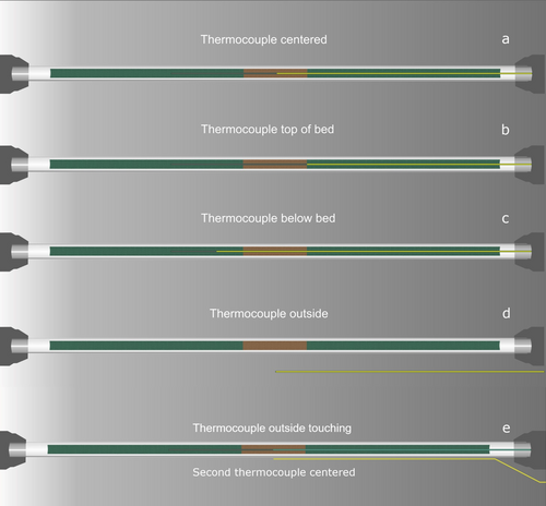
For recording the temperature profile of the corresponding reactor material, the setup was operated either under inert conditions, that is, heating to 600 °C in pure N2, or under NH3 decomposition conditions. In the latter case, the reference thermocouple to control the furnace was placed touching the outside of the reactor tube. After reaching the desired temperature, the temperature inside of the reactor was logged with the inner thermocouple initially positioned as far into the reactor as possible and then carefully pulled out in steps of 5 mm.
2.6 Pressure Drop Experiments
The effect of the inert material and catalyst sample particle size, especially relevant for samples that cannot be adequately transformed to a desired sieve fraction, was investigated based on pressure-drop-dependent conversion experiments. The performance of a Ru-based reference catalyst in the FST was evaluated for a range of distinct sieve fractions, while the pressure directly upstream (PT1, Figure 1) and downstream (PT2, Figure 1) of the reactor assembly was recorded. To account for the effect of the inert material, a catalyst bed of pure γ-Al2O3 in the same sieve fractions was tested equivalently. The SiC used in the regular tests as the inert material was not applicable in these investigations, as it is not feasible to press and sieve SiC to the required particle sizes.
3 Results and Discussion
3.1 General Considerations and Reproducibility
Besides general considerations for the design of a laboratory-scale flow setup,[8] the most important aspect for a setup designated to benchmark heterogeneous catalysts is the ability to conduct reliable and above all reproducible measurements to ensure the comparability of the results. Although this applies to any kind of reactor setup, it is even more important for a screening setup, as the number of catalysts tested and thus the number of results is high and a lack of reproducibility would severely limit the usefulness of the setup. To limit the influence of operator errors or even deviations in controlling timings or parameters when running the setup, the setup was automatized. All valves are pneumatically switched and the user can predefine a recipe for the gas flows and heating ramps using the control software. The temperature of the furnace is regulated via cascade control, which was optimized according to the requirements. The different sections of the setup were constructed as exact copies with the same materials and components. To prevent deviations from potential adsorption of products on downstream components or deviations in the product gas analysis originating from temperature differences, the entire downstream section is heated to a constant temperature of 50 °C via trace heating and a hotbox which accommodates all of the downstream valves.
The ammonia decomposition reaction induces a distinct heat tone and is intrinsically sensitive toward reaction temperature. For this reason, the positioning of the reactor tube in the furnace in relation to the isothermal zone, the packing of the catalyst bed, as well as the choice and placement of the reference thermocouple for temperature regulation of the furnace are critical aspects affecting the comparability between measurements. The latter aspect is outlined in detail in a subsequent segment of this publication. To minimize the effect of reactor tube placement, the isothermal zone of the laboratory furnace was confirmed by recording vertical temperature profiles and marking the center of the isothermal zone.
3.2 Realizing Inert Conditions
Besides temperature control, the choice of the reactor material is also of critical importance for the comparability of measurement results from a research ammonia decomposition setup. The material has either to be inert to the ammonia decomposition reaction under the chosen reaction conditions or at least give a stable blank activity at minimal conversions without material activation or deactivation. At the same time, the material needs to withstand the corrosive potential of ammonia at elevated temperatures. For industrially relevant conditions, this would mean pure ammonia at 400–600 °C.1 In agreement to this, the usage of pure ammonia is the usually chosen feed gas composition for ammonia decomposition tests in the literature, as shown by a systematic sampling of 201 publications listed in a review by Lucentini et al.1 (see Figure 4a). A broad number of different reactor materials have been reported for ammonia decomposition research. A comprehensive overview is compiled in Figure 4b., retrieved from the same 201 individual publications. It is important to note that special care has to be taken to ensure absolutely leak-tight connections when using different materials for the reactor and the upstream and downstream gaslines.
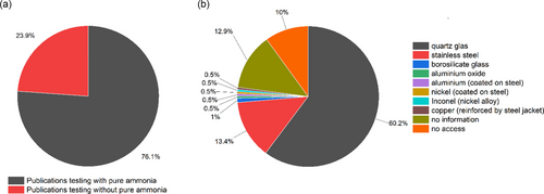
The most prominent material classes for reactors in research are SiO2-based glasses (quartz, borosilicate), where quartz glass is clearly the dominant phase as borosilicate glasses are less temperature resistant. Among the various geometric reactor forms, tubular reactors are frequently used in gas-phase reactions, that is, also heterogeneous gas-phase catalysis. While silicate glass reactors benefit from a generally high-temperature tolerance and chemical inertness in most reactions, these reactors suffer from low mechanical stability and can thus pose a potential threat when operated with dangerous (flammable, toxic, etc.) components due to the inherent risks of leaks or structural damage.
As shown in Figure 5, the quartz glass reactors used in our studies were completely inert in the ammonia decomposition FST over four consecutive experiments. No further activation could be observed, neither with an empty nor with a SiC-filled reactor. Leak-tight connections between the quartz glass reactors and the steel components of the gas feed- and downstream sections were routinely achieved using ultra-Torr connectors. However, the comparably low structural strength of the quartz tube reactors made an inert extraction of the reactor assembly with attached bellows-sealed valves challenging. To counteract this and to significantly simplify the handling, uncoated and coated stainless steel tubes as well as molybdenum reactors were investigated for their suitability as reactor materials in ammonia reforming.
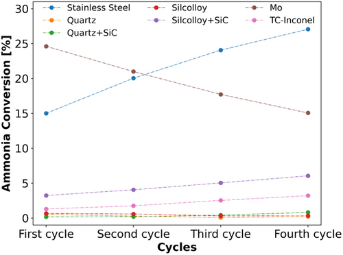
Steel is a very prominent example for general reactor construction due to the wide range of possible modifications with distinct material properties. The variety of different techniques available to achieve leak-tight connections make it a versatile material. As shown in Figure 4b, it is also used as reactor material for ammonia decomposition in a number of publications. In this work, 1/4″ tubular flow reactors made from 1.4435 (AISI 316 L) stainless steel tubing were used. However, the empty steel reactor displays a significant activity with about 15% conversion at 600 °C already in the first FST run, as demonstrated in Figure 5. Consecutive FST cycles lead to a further activation of the steel, resulting in more than 25% ammonia conversion at 600 °C after the fourth cycle.
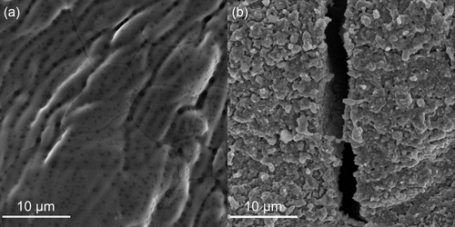
As iron-based catalysts are known to be active in ammonia decomposition,1 one can assume that some of the iron content of the steel reactor is activated under reaction conditions. Furthermore, even austenitic steel, like the 316 L used in this study, has been found to marginally suffer from hydrogen corrosion.[6] The repeated exposure to H2 at elevated temperatures could thus have led to surface defects of the steel tube walls affecting the activity in ammonia decomposition. Considering the Fe–C–N phase diagram, an increase in the N molar fraction could drive changes, that is, the formation of nitrides, in the steel structure at the prevailing temperatures of the FST.[9] This assumption is corroborated by the observation of ammonia released in the product gas stream during subsequent reduction cycles with pure hydrogen in four consecutive FST-runs of a SiC-filled steel reactor tube (see Figure S4, Supporting Information). Scanning electron microscopy (SEM) images of the reactor tube before and after exposition to the FST cycles underline that the reaction conditions induced significant surface changes in the material, as the formation of cracks and severely increased roughening can be observed (Figure 6, Figure S5 and S6, Supporting Information). Iron oxide seems to be present on the surface of the used reactors, while the content of other d-metals seems to decrease in the surface layer. The oxygen content observed using energy dispersive X-ray (EDX) mapping was increased strongly after NH3 decomposition compared the to the unused steel reactor (Table S1, S2 and Figure S6, Supporting Information). This probably originates from the noninert conditions during the extraction of the reactor. Generally, pure stainless steel reactors are not suitable for the targeted application due to their susceptibility to hydrogen and/or ammonia corrosion.
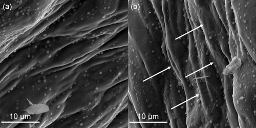
Steel reactors with amorphous silicon-based coating (Silcolloy) suitable for the application at high temperatures (1140 °C) should significantly improve the corrosion resistance as well as provide an inert reactor surface, since the coating prevents the contact between the reactant gases and the steel tube surface. EDX mappings confirm a high and homogeneous Si content on the surface of an unused Silcolloy-coated reactor (Figure 7, Figure S7 and Table S3, Supporting Information). When an empty reactor is employed, the coated steel proves to be inert in the ammonia decomposition cycles (Figure 5). However, if SiC is used as an inert material, an increasing activation can be observed over the course of four FST cycles, resulting in roughly 5% NH3 conversion at 600 °C in the last experiment. This is related to a compromised integrity of the coating due to the abrasive properties of SiC, as shown by signs of damage and displacement at the inner reactor surface after exposing the reactor to reaction conditions (Figure 7). The absence of the Si coating at the regions with visible damage is further confirmed by EDX (Figure S8 and Table S4, Supporting Information). Accordingly, the origin of the observed activation of the Silcolloy-coated reactor in ammonia decomposition is similar to the uncoated stainless steel reactor. Still, even when SiC causes abrasion of the coating, the effective exposed iron surface in the reactor wall is lower than for uncoated reactors and consequently the effect on the conversion is not as severe.
A potential utilization of Inconel 600 (NiCr15Fe), well-known for its high resistance toward corrosion, is discarded due to continuous activation over four fast screening cycles with a blank Inconel-coated thermocouple positioned inside the center of the SiC-filled reactor (Figure 5). This observation simultaneously corroborates the imperative use of a coated immersion tube during experiments when a thermocouple is placed inside the catalyst bed.
In contrast, fast screening cycles with the Mo reactor tube result in a very high initial activity with close to 25% conversion at 600 °C (Figure 5), while consecutive cycles lead to deactivation. Further exposure to the reaction conditions in ammonia decomposition indicates an ongoing deactivation (Figure S9, Supporting Information). Similar to the stainless steel reactor, this is related to cracking of the Mo tube surface (Figure S10 and S11, Table S5 and S6, Supporting Information), indicating the occurrence of reactions and strong phase changes on the reactor surface under reaction conditions. While on the laboratory scale it is possible to use quartz as a reactor material for flow setups, these initial investigations already indicate that in particular the selection of the suitable reactor material poses a major challenge for the industrial application.
3.3 Endothermicity and Temperature Control
Comparing the catalytic activity between different materials is challenging, since each material has a different thermal conductivity and different activity, causing different thermal profiles which in turn affect the activity creating a vicious cycle. As ammonia decomposition is a markedly endothermic reaction (45.9 kJ mol−1),[10] the temperature profile formed inside the catalyst bed affects the control of the temperature and subsequently the conversion. Accordingly, the conversion determined is strongly influenced by the position of the thermocouple with respect to the catalyst bed (Figure 8a,b), whereas the apparent difference in conversion is only caused by the influence of the temperature drop on the temperature control. Thus, the comparison of the activity among different catalysts is only possible if the temperature control is independent of the endothermicity of the ammonia decomposition reaction. Comparing the temperature profiles of a Ru- and a Fe-based catalyst bed under inert and reaction conditions demonstrates the impact of the temperature control (Figure 8c–f). For these measurements, the thermocouple inside the immersion tube was used to record the T-profile, while the thermocouple outside of the reactor was used as reference for oven control. To keep the parameters comparable, the outer thermocouple was kept in the identical vertical position relative to the reactor center, while simultaneously touching the reactor tube with the tip (Figure 3e). Independent of the type of temperature control, the endothermicity of the ammonia decomposition leads to a significant drop of the temperature inside the catalyst bed, but the profiles differ depending on the way of controlling the temperature as well as on the activity and thermal properties of the catalyst system. This behavior was confirmed for all four sections of the flow setup. If the temperature control of the furnace was based on the thermocouple inside the catalyst bed, it is obvious that the resulting real furnace temperature would severely depend on the catalyst as well as the position of the thermocouple inside the reactor tube. As the cooling effect of the endothermic reaction is also transported across and affects the outer temperature of the reactor tube, the reference thermocouple positioned outside of the tube registers a seemingly too low temperature, which leads to overheating of the furnace, resulting in higher temperatures of the surrounding inert material (Figure S12 and S13, Supporting Information). The significant differences in conversion depending on the position of the thermocouple (Figure 8a,b) directly correspond to the shape of the temperature drop. As the endothermicity of the decomposition reaction leads to a decreased temperature already in front of the catalyst bed, the resulting excess temperature of the furnace leads to higher conversion values compared to the configuration with the reference thermocouple positioned outside. Positioning the thermocouple in the center of the catalyst bed, and therefore in the immediate vicinity of the most pronounced temperature drop, leads to the highest excess temperature of the furnace and thus to the highest conversion values.
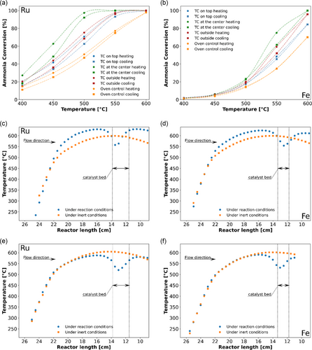
Since the reaction temperature significantly affects the furnace regulation, the experiment comparability suffers when the temperature of the furnace is controlled using a thermocouple inside the reactor. As referencing the temperature control of the furnace on the catalyst bed is however often accepted as the most desired option for accurate measurements, the described inherent challenges of the ammonia decomposition reaction could very well contribute to the significant catalyst activity discrepancies reported in literature studies. To counteract the falsification of the reaction temperature, a thermocouple positioned inside of the furnace (usually used as a benchmark for the temperature safety limiter) was instead used for the cascade control. The temperature settings were adjusted accordingly to reach the desired 600 °C inside of the reactor tube under inert conditions (Figure S14, Supporting Information). For calibration of the furnace temperature control, further temperature profiles inside of the filled reactor under inert and reaction conditions were recorded. As expected, the drop in catalyst bed temperature is still clearly visible (Figure 8e,f), but the furnace no longer overheats. Instead, the change to direct furnace temperature control resulted in improved conformity of the profiles above and below the catalyst bed under inert and reaction conditions, independent of the chosen catalyst and thus the temperature tone of the catalyst bed at the applied conditions. The effect was reproducibly validated for all four sections of the flow setup (Figure S15 and S16, Supporting Information). In addition to SiC, Al2O3 and SiO2 were tested as inert materials (Figure S17, Supporting Information). The height and width of the temperature drop is less significant for SiC, indicating that the superior heat conductivity of this inert material contributes to leveling and stabilizing the temperature in the catalyst bed. Future studies to obtain relevant kinetic parameters have to be carried out under differential conditions to ensure that the endothermicity of the reaction does not influence the results.
3.4 Volumetric Expansion of the Products
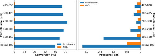
As the reaction duplicates the moles of compounds (Equation (1)) causing a volumetric expansion in the process, the effect of a potential pressure drop caused by the use of a too small catalyst particle size can be strongly enhanced at high ammonia conversions. For particle fractions below 200 μm of the Ru-based reference, the reaction pressure increased significantly with diminishing particle sizes (Figure 9). Simultaneously, this resulted in lower conversions as, according to the principles of Le Châtelier, higher pressure would favor the reverse reaction rather than the ammonia decomposition reaction. The increase in pressure can mostly be ascribed to the volume expansion caused by the reaction, indicated by comparative measurements with pure Al2O3, where a small increase in pressure could be observed only for the smallest particle fraction (below 100 μm). As the conversion for Al2O3 was below 1% in all measurements, this material was deemed inert, in turn allowing us to evaluate the pressure drop caused by only the difference in catalyst particle size. In this context it has to be mentioned, that reaction kinetics might also induce a lower conversion, as an increased partial pressure of H2 inhibits the ammonia decomposition.[11] For particle fractions above 200 μm no pressure drop was observed, but larger fractions above 300 μm lead to reduced conversion, indicating mass transport limitations. The detailed values of conversion and pressure drop are listed in the Table S7, Supporting Information. In summary, the particle fraction of 200–300 μm was found to be the optimum under the chosen reaction conditions, minimizing the influence of volume expansion as well as mass transport limitations on the data obtained. Furthermore, this allows the assumption that the performance of any catalyst tested under the optimized reaction conditions is not affected by this parameter if it exhibits equal or lower conversion than the applied Ru reference catalyst.
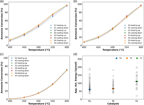
Based on the described investigations, the comparability of ammonia decomposition experiments and the respective results in the four different sections of the home-built test rig are carefully tested using industrial Ru-, Ni- and Fe-based catalysts as reference. As shown in Figure 10, for the reference catalysts, the discrepancy between the four segments regarding NH3 conversion at 550 °C is below 2.3%, proving a reasonable reproducibility for future catalyst screenings.[12] Likewise, the determined mean apparent activation energies Eapp of the tested reference catalysts align very well with the distribution of values reported in the literature (Figure 10d). It is noteworthy that the apparent activation energy values were calculated only for means of this comparison, as well as an additional numerical parameter to grade the reproducibility of the individual sections of the setup.
4 Conclusion
Up to date, there is no large-scale application of ammonia reforming, and a material that is overall suitable to fill the role of an industrial ammonia decomposition catalyst is yet to be identified. However, some generally available industrial catalysts, while not optimized for this specific reaction, nevertheless exert high activities. This is a promising starting point for focused research on the identification and optimization of an industrially relevant ammonia reforming catalyst. One of the biggest obstacles on the road of fundamental screening studies is to ensure reasonable and comparable test conditions for the newly developed materials. For this, the right choice of reactor material is crucial, since it not only has to withstand the decidedly harsh reaction conditions, but also needs to be completely inert without any signs of activation. Simultaneously, the material needs to exhibit a high mechanical strength for a potential transport of the reactor tube assembly, for example, if an inert extraction of the catalyst and thus the reactor itself is desired. As shown above, quartz tube reactors are applicable in flow setups on a laboratory scale, but for investigations at elevated pressure or industrial applications, finding a suitable reactor material poses a major challenge that has to be addressed in parallel to the catalyst development. In addition, the endothermicity and the volume expansion of the ammonia decomposition reaction must be carefully considered to establish appropriate experimental conditions and control of the experiments. Despite the many different challenges that have to be met when designing a test rig for the generation of reliable and reproducible data from ammonia decomposition experiments, we were able to construct a screening setup which can be operated under industrially relevant conditions and thus contribute to the identification of promising catalyst materials.
Acknowledgements
The authors thank the Federal Ministry of Education and Research, Germany (Bundesministerium für Bildung und Forschung, BMBF, TransHyDE Forschungsverbund AmmoRef, support code: 03HY203A) for funding. The catalysts used in this study were kindly provided by our project partner Clariant.
Open Access funding enabled and organized by Projekt DEAL.
Conflict of Interest
The authors declare no conflict of interest.
Open Research
Data Availability Statement
The data that support the findings of this study are available from the corresponding author upon reasonable request.


