Development of a Spherical High-Pressure Tank for Hydrogen Storage in Mobile and Stationary Applications
Abstract
In the sub-project Mukran of the BMBF-funded flagship project TransHyDE, spherical and nearly spherical-shaped (isotensoids with short cylindrical spacer) high-pressure tanks are developed for hydrogen storage. This article presents the planned work of the Chair of Polymer-based Lightweight Design at the BTU Cottbus–Senftenberg and the research division PYCO at the Fraunhofer IAP. The research topics include the fiber-compatible design of the liners, the rule-based optimization of the layer structure of the load-bearing overwrap made of carbon fiber-reinforced plastic, the development of a fiber placement strategy, and the integration of the tanks into a frame as a mobile storage solution.
Hydrogen is expected to become the energy carrier of the future. In order to achieve this, technologies are needed not only for its production and reconversion into electricity or other utilization but also for its transport. Mukran investigates storage and transport of gaseous hydrogen under high pressure in order to supply consumers who are not connected to a H2 pipeline network. Therefore, storage vessels are being developed that are characterized by an optimal compromise between installation space and a load-as well as material-appropriate geometry and thus enable efficient transport with a high payload ratio.
1 Introduction
To mitigate the negative impact of climate change on human health, agricultural production and the global economy, the energy supply must be transformed into a renewable energy economy.[1-3] For this, hydrogen technologies are crucial[4-6] and, in turn, efficient storage facilities are necessary. Since storage at 350 and has an inherent energy requirement of just 12% and 15% for compression, respectively,[7-9] it complies the demand for an efficient storage technology and therefore is studied in this article.
Note: The term “vessels” here refers to tanks as high-pressure storage systems for gaseous hydrogen. The terms “vessel” and “tank” are used synonymously.
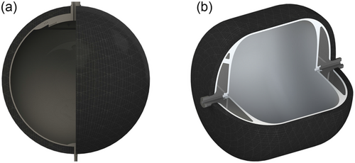
In the research project Mukran, type 3 and type 4 tanks are to be developed in addition to a novel steel-based solution. The storage technology shall be suitable for transporting hydrogen mainly by trucks, but also by rail and ship, so that the growing demand for hydrogen[10, 11] can not only be produced but also transported to decentralized sites. The type 3 tank (Figure 1a), i.e., a high-pressure storage system with a hydrogen-tight metal liner and a load-bearing overwrap made of carbon fiber-reinforced plastic (CFRP) is spherical. Due to this shape, semi-finished products can be used for liner production, thus minimizing costs.
The optimized design of the CFRP shell shall allow high operating pressures to be achieved even with large tank diameters of up to with a high payload ratio. The planned activities for the development of the latter system are described in this article. CFRP features very high specific strengths and stiffnesses and is thus predestined for lightweight construction. The resulting aimed advantages of the design with metal liner and CFRP overwrap compared to a pure metal variant made of known standard boiler alloys are summarized in Table 1 and described in the following.
| Monolytic steel vessel | Type 3 tank | |
|---|---|---|
| Material | Steel | Steel and CFRP |
| Low specific strength of boiler alloys (without safety factor) | High specific strength of CFRP (unidirectional) | |
| Wall thickness | Thick steel wall | Thin metal liner and light CFRP overwrap |
| for , | Liner 5–10 mm; wrap 75– for , | |
| Joining | Special welding techniques | Standard welding techniques for the liner |
| Manhole | Bolt or flange connections | Overwrap with CFRP |
| Payload ratio | 0.4% | 2.0% |
| , , | , , |
The first benefit of the CFRP tank over known pure steel vessels is the comparatively low wall thickness of the metal liners, which can thus be manufactured from semi-finished products using common welding techniques. For a spherical steel tank made from a standard boiler steel, a required wall thickness of can be estimated approximately using Equation (1) (diameter , operating pressure burst pressure , tensile strength P355NH – 1.0565 ,[12] safety against hydrogen embrittlement and corrosion 2 ). On the one hand, this results in a dead weight that is too high for mobile applications, and on the other hand, the welding of such high and greater wall thicknesses in the required qualities is associated with a great deal of effort and special processes .[13, 14] For the lighter type 3 vessels, in contrast, the aim is to achieve a liner wall thickness of 5–10 mm that is good for welding and a CFRP wrap thickness of 75–105 mm (, , depending on the fiber- and matrix-type, the manufacturing technique/tolerances and fiber volume content). Comparing the wall thicknesses, it should be considered that the steels have a density of and CFRP of only .
Another advantage of the type 3 tank is that the manhole, which is required during the manufacture of the liners for finishing and inspection of the weld seams, can be overwrapped and no bolts or flange connections are necessary. However, to fully exploit this potential, a health monitoring system is required, the development of which is also the subject of this research project.
In type 4 tanks, the liner is made of a polymer and only the bossparts are still made of metal. As the plastic can withstand higher elastic elongation than hydrogen-compatible metals, the CFRP of the load-bearing shell can be better utilized and the lightweight construction potential can thus be optimally exploited. Furthermore, plastics offer greater design freedom. For example, the geometry shown in Figure 1b, consisting of two isotensoids and a cylindrical intermediate piece, not only makes better utilization of the given cube-shaped installation space, but also allows a liner geometry (the calculated isotensoid shape) to be realized with which the fibers are optimally loaded in tension. Thanks to these advantages, tanks with a gravimetric efficiency of between 6 and 10% shall be developed.
The main tasks in the Mukran project for the development of the CFRP tanks are outlined in the following. The special feature of the tanks to be developed lies in the optimal utilization of the given almost cube-shaped installation space. In addition, the two technologies fiber winding and automated fiber placement as well as the corresponding material systems with thermoset and thermoplastic matrix are compared for the manufacturing of the tanks.
2 Design of Fiber Reinforced High Pressure Tanks
Unidirectional continuous fiber reinforced plastics have strongly anisotropic properties. Unidirectional means that all the load-bearing fibers have the same orientation. The matrix, the polymer, protects and supports the fibers so that they do not buckle under compressive load. Furthermore, the matrix transfers the loads between the fibers.
Due to its anisotropic properties, CFRP poses special design and manufacturing challenges. The fibers must be aligned as precisely as technically possible along the load path. This is possible with automated or partially automated manufacturing technologies such as winding or Automated Fiber Placement (AFP) (see Section 4). However, before this can be done, the layer structure must be designed according to the loads and boundary conditions. For this purpose, numerical and analytical approaches are used for calculation and optimization (see e.g., Ref. 7) to determine a layer structure that corresponds to the complex stress conditions, especially in the area of connections, the outlet and sensors.
In the first step, the manufacturing technology-dependent material properties are determined experimentally. Based on this, the calculation models are created and the optimization algorithms are implemented. In the research project, rule-based optimization is to be carried out. This means that the restrictions from production are already introduced into the optimization as constraints. In this way, an optimum is generated that can be implemented with the corresponding manufacturing technologies and thus requires fewer iterative process steps for post-processing and adaptation. Examples of such parameters originating from production are the minimum and maximum filament pretension, minimum and maximum fiber angles, tape and roving widths, layer thicknesses, and minimum and maximum radii that can be deposited.
The results are validated in experimental non-destructive and destructive tests on diameter demonstrators (pressure and burst tests). It should be noted that only the design up to a diameter of is carried out. Due to the time available for the research project, the demonstrator scale will not be exceeded during manufacturing.
3 Structural-Health-Monitoring-System
The safety of the tanks must be ensured over the entire lifetime of both the stationary and the mobile systems. On the one hand, appropriate safety factors are taken into account in the design process and the stresses on the structure are analyzed in detail in simulations and experiments (see Section 2). On the other hand, a structural health monitoring system will be developed and implemented. Among other things, the strains on the liner surface and at different positions in the ply structure will be monitored. These positions will be selected according to the results of the numerical calculations for the evaluation criterion of the stress of the CFRP in Section 2. Other variables to be monitored are the hydrogen concentration near the tank, the location (GPS) of the tank, the fill level and internal pressure, as well as the ambient temperature.
Suitable sensors are identified in a market study. In addition to strain gauges, fiber optic sensors are frequently used to record the strains. However, preliminary investigations showed that the latter sensors interfere with the layer structure due to their comparatively large diameter and thus reduce the load-bearing capacity of the laminate. For this reason, sensors specially designed for the tank and liner geometry are to be additively manufactured from inks with different electrical conductivities in the research project at Fraunhofer IAP. A system will be designed with which the data can be retrieved contactlessly via the Internet. In addition, artificial neural networks are being designed to detect anomalies that indicate the need for maintenance.
4 Development of the Manufacturing Strategy
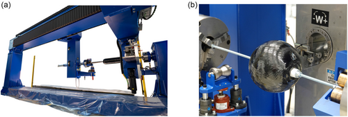
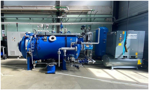
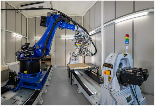
The partially automated winding process allows high reproducibility and quality assurance during production.[15, 16] Duroplastic systems are used in this process. The roving coils are located in a creel. Actuators are installed in this creel, with which the yarn tension can be adjusted. The rovings are fed to the deposit unit, where they pass through a resin bath (wet winding). The liner is clamped on two sides in the winding unit (Figure 2). Further actuators allow process-controlled rotation of the liner. In this process, the deposit unit moves along the axis of rotation. Since the movements are coordinated in the programming of the manufacturing sequence, the fibers are thus deposited according to the previously designed layer structure. Curing takes place in the autoclave (Figure 3) under application of a temperature program and pressure. Dry fiber winding is an alternative to wet winding. Here, the rovings are not impregnated in a resin bath during the winding process, but the resin is subsequently introduced by infusion in the autoclave. Another alternative is the use of tow pregs. This material is a semi-finished fiber product that is already impregnated with a resin. In this research project, the variants are to be compared with each other and a manufacturing process is selected on the basis of the results. The process times, costs and tolerances and their influence on the structural mechanical behavior of the tanks will be used as evaluation criteria. Furthermore, a comparison will be made with an alternative manufacturing technology, Automated Fiber Placement (AFP, Figure 4). In contrast to winding, also thermoplastic tapes can be processed with this technology. Since the thermoplastics can be remelted, unlike the thermosets, they are much easier to recycle. In AFP, the tapes are melted by heating elements (laser or infrared radiator) and deposited on the workpiece. They are pressed onto the workpiece by a roller. The deposited tape then cools below the softening temperature in the continuous manufacturing process. This significantly reduces the risk of the fiber material slipping off the liner during the production process compared with winding. For both manufacturing technologies, a parameter study is conducted to design optimal process control. The parameters include the pretension, the contact pressure, the angle of the depositing head of the AFP to the liner, the amount of heat applied and the process speeds. The in-situ implementation of the sensors of the structural health monitoring system poses a great technological challenge.
5 Frames for the Transport and Stationary Storage of the Tanks
For the transport and use of the tanks in the logistics chains of shipping, rail, and road transport, they must be integrated into a frame or container structure that matches the requirements of these transport systems. On the one hand, the connection points (twistlocks) must be set and designed in such a way that they correspond to the technologies available at ports, on the means of transport, and at the loading stations; on the other hand, the accessibility of the sensors and valves must be ensured for use at filling stations and as temporary storage tanks. Another important aspect is the structural–mechanical influence of the frames on the tanks. For example, no metallic edges of the frame must be allowed to press into the CFRP shell of the tanks, as CFRP is very sensitive to such load cases. It must also be possible to ensure this in the event of a crash. In addition, safe storage must be ensured despite the changes in pressure causing the tanks to deform.
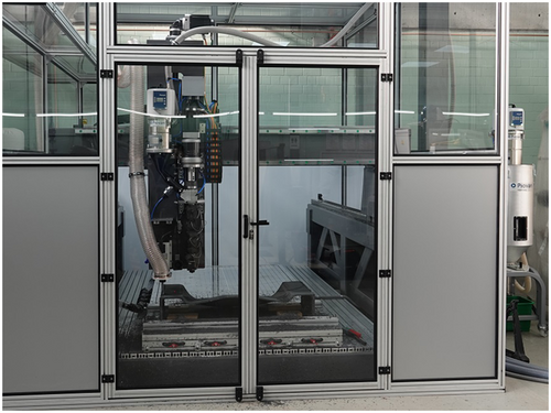
Two approaches will be considered and evaluated in terms of manufacturing times, stability and strength, and inherent mass. The first concept is a structure made entirely from a polymer by additive manufacturing. A hybrid manufacturing cell is available at the BTU for this purpose (Figure 5). As a second concept, a steel frame is being developed as a welded structure. In this variant, the supports for the tanks are also to be additively manufactured from a polymer in order to minimize the orthogonal loading of the CFRP by edges. The frames and their influence on the structural mechanical behavior of the tanks will be analyzed using numerical calculations and validated in experimental tests with demonstrators. The manufacturing process will be designed in a parameter study to determine the printing speed, mass flow rate, nozzle temperature, melt temperature, nozzle diameter and the control of a cooling device.
6 Conclusion
In the research project Mukran (start date: 15.05.2023), which is funded by the BMBF as part of the TransHyDE flagship project, the Chair of Polymer-based Lightweight Design at the BTU and the research division PYCO as well as the research group of the Center for Sustainable Lightweight Technologies ZenaLeb at the Fraunhofer IAP are working together with the project partners to develop high-pressure storage systems with a target operating pressure of as large-scale structures and validate them on scaled demonstrators. The layer structure of the type 3 tanks will be designed with the aid of optimization algorithms. The size range from 600 to 2400 mm will be considered. Two manufacturing strategies, winding and AFP placement, are being developed on diameter demonstrators. The development of a structural health monitoring system will increase the safety of the storage technology. The vessels will be validated in pressure and burst tests. A frame for the tanks will be designed to ensure a wide range of applications for the system, from stationary use at filling stations and as temporary storage to mobile use by ship, rail, and especially by truck.
Acknowledgements
This work is carried out as part of the research projects “Sphärische Hochdrucktanks zur Wasserstoffspeicherung” and “CFK-Kugeltank zur Wasserstoffspeicherung” (funding code 03HY206G and 03HY206H), which are funded by the German Federal Ministry of Education and Research (BMBF) and are part of the sub-project “Mukran – Erforschung innovativer Speicher- und Transportlösungen” of the flagship project TransHyDE.
Open Access funding enabled and organized by Projekt DEAL.
Conflict of Interest
The authors declare no conflict of interest.


