The Influence of Calendering on the Fast Charging Performance and Lithium Plating of Hard Carbon Blend Anodes
Abstract
Lithium-ion batteries ensuring high energy densities are the focus of ongoing research. The main challenge is the fast charging capability, which is restricted by transport limitations of the lithium-ions. For this reason, graphite (Gr) and hard carbon (HC) blend anodes at different calendering degrees and, thus, electrode densities are investigated in terms of their structural features as well as their electrochemical performance. The motivation of blend anodes is the combination of the advantageous properties of these materials. Due to the different microstructures of Gr and HC, major differences in the lithiation process can be found. While the turbostratic structure of HC enables fast charging, its large specific surface area is associated with a low initial Coulombic efficiency and, thus, a loss of capacity. Consequently, the combination with Gr in blends is reasonable. While the lithium-ion diffusion is enhanced using HC, the availability of the interporous structure of HC is highly dependent on the electrode density. In addition to an increase in adhesion strength and reduction in electrical resistance, a reduction in tortuosity and lithium plating can be demonstrated. Furthermore, a higher capacity retention in the charge rate test (up to 3C) at low coating densities was found for the blends.
1 Introduction
The demand for lithium-ion batteries (LIBs) has become omnipresent in recent years due to their various requirements and applications, from consumer electronics to electric and plug-in hybrid vehicles.[1-3] On the anode side of LIBs, graphite (Gr) was the material of choice for a long time, as it stands out with a high cycling stability, electrical conductivity, safety, and low costs.[4-7]
However, one of the major challenges in the application of LIBs, so far, is the fast charging capability, which is limited by the lithium-ion diffusion through the anode.[8, 9] Despite the abovementioned advantages of Gr, other active materials must, therefore, be considered to further improve the battery performance. A promising active material that is under investigation, especially to enhance the fast-charging ability of the anode, is hard carbon (HC).[10, 11]
Compared with Gr, which consists of an ordered structure of graphene layers, HC shows a disordered structure of carbon layers featuring many defects and pores within the material.[12-14] As a result of this structural difference, the lithium intercalation mechanism in HC is substantially dissimilar to the intercalation mechanism in Gr. The disordered structure of HC enables shorter diffusion paths and, thus, allows the lithium ions to diffuse faster through the pores of the material. Furthermore, the structure provides a larger electrode–electrolyte interface, which eventually enables higher charge rates than in Gr.[15, 16] An additional feature that makes HC a promising suitable material for fast charging in LIBs is its high working potential and low-temperature behavior, which, in turn, means that HC anodes will much less likely suffer from undesirable lithium plating compared with Gr anodes.[17, 18] The main challenge when using HC, however, is its low initial Coulombic efficiency due to its high specific surface area and the low energy density compared with Gr.[19, 20] Consequently, a combination of these materials in blend anodes could be a promising strategy to enhance the overall electrochemical performance by considering both the high power and high energy density in the anode.[11, 21]
In addition to the fast charging capability, the energy density should be still at a high level. Calendering not only leads to the reduction of coating defects, but also an increase in the energy density (kWh L−1) via a reduction in porosity and layer thickness and, thus, to an increase in the range of the LIBs.[22, 23] Therefore, the step of calendering is crucial for the electrode performance. As the decrease in the porosity of the electrode is associated with a higher ionic resistance and an increase in tortuosity, there is a risk of reducing the fast charging capability by a too large compression due to ionic diffusion limitations.[24] This aspect is particularly important when using active material blends with active materials of different particle structures and sizes as the porosity can be affected by this. Therefore, this study focuses on the investigation of blend anodes containing Gr and HC and the effect of different calendering degrees and, thus, electrode densities on the mechanical, structural, and electrochemical properties.
2 Experimental Section
To investigate the differences between Gr and HC as well as their combination with each other, electrodes of the pristine raw materials and different blends were produced and analyzed in terms of their structural properties and electrochemical performance.
The following chapter specifies the materials and methods used to manufacture the beforementioned anodes.
2.1 Anode and Cathode Materials
Gr and HC were used as active materials for the anodes. An overview of the anodic material properties is given in Table 1.
| Name | Description | Specific capacitya) [mAh g−1] | Densitya) [g cm−3] | Particle size x50 [μm] | Specific surface areaa) [m2 g−1] |
|---|---|---|---|---|---|
| Gr | Surface modified | 360 | 2.26 | 19 | 2.9 |
| HC | Turbostratic | 350 | 1.40 | 5 | 6 |
- a) Manufacturer's specifications.
To give an overview of the structural differences between the active materials used within the anodes, scanning electron microscopy (SEM) images and the particle size distribution of the materials as well as a schematic representation of the lithiation in Gr and HC are shown in Figure 1.
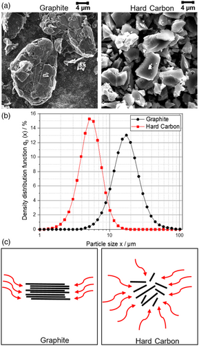
For the Gr material, the graphene layers of the stacked Gr particles were clearly visible. The image of the HC shows the disordered structure of the significantly smaller amorphous HC particles where the graphene layers are stacked and located at uneven distances and angles to each other. Furthermore, small pores can be seen in the particles, indicating the defects in the particle structure of the HC, which entails an interporous structure of the particles. The major optical differences are an indicator for a very different lithium intercalation into the active material. In HC, the lithium ions intercalate not only laterally, as for Gr, but from any position. This significantly provides more target points for intercalation and, therefore, is a possibility to improve the charging rate by reducing tortuosity.
An overview of the formulations for the anodes and reference cathode, which served for all the anodes as a counter electrode, is given in Table 2.
| Anode | Gr [wt%] | HC [wt%] | Carbon black [wt%] | Binder (CMC + SBR) [wt%] |
|---|---|---|---|---|
| Gr | 93.0 | – | 1.40 | 5.60 (2.10 + 3.50) |
| Gr/HC blend | 83.7 | 9.3 | 1.40 | 5.60 (2.10 + 3.50) |
| Cathode | NCM 622 [wt%] | Conductivity additive [wt%] | Binder [wt%] | |
| NCM622 | 95.5 | 2.25 | 2.25 |
For the anode, an industrial carbon black was chosen as conductive additive and binders such as sodium carboxymethyl cellulose (CMC) as well as styrene–butadiene rubber (SBR). A solvent of distilled water was used.
A conventional NCM622 was chosen as active material of the cathode, polyvinylidene fluoride (PVDF) as binder, and carbon black as conductivity additive. A solvent of N-methyl-2-pyrrolidone (NMP) was used.
2.2 Slurry Preparation and Electrode Manufacturing
First of all, two different anode slurries with different compositions according to Table 2 were prepared. The reference contained 100% of Gr as active material, whereas the Gr/HC blend anodes contained 90% Gr as well as 10% HC as active material. The carbon black as well as the binder amount was kept constant in both the electrodes. For the preparation of the anode suspension, the dry components were mixed in a TURBULA 3D shaker mixer of Willy A. Bachofen AG for 15 min at 49 rpm with the purpose of creating a homogeneous powder mixture. The powder mixture was then dispersed in deionized water (solids content = 50 wt%) at a tangential speed of 9 m s−1 for 45 min at 15 °C in the DISPERMAT dissolver from VMA-Getzmann. Here, a 600 mL batch and a dissolver disk with a diameter of 50 mm were used. Finally, the shear-sensitive binder SBR was added at a smaller tangential speed of 3 m s−1 for 15 min, while the suspension was degassed to prevent the formation of air bubbles in the slurry. Afterward, the final paste was coated on copper foil (10 μm) using the LABCOATER-type «LTE-S» from Werner Mathis AG to a mass loading of 4 mAh cm−2 at 60 °C drying temperature and 8 min drying time. The final step of the calendering was performed discontinuously with a pilot-scale two-roll compactor GKL 400 (SAUERESSIG) at a speed of 1 m min−1 at 20 °C. The calender roll diameter was 450 mm and the roll width was 470 mm. The line load was calculated from the rolling force and the coating width of the electrode sheets of 160 mm. The coating thickness was measured with a dial indicator (Mitutoyo 543-300B) with a margin of error of 0.003 mm. The thickness was measured at approximately six points on each electrode sheet.
The mean values of the different calendering densities, the line load while calendering, coating thickness, and the theoretical porosity, which were determined from the coating density and the weighted material densities (see Table 1), are listed in Table 3.
| Anode | Density [g cm−3] | Line load [N mm−1] | Coating thickness [μm] | Porosity (theoretical) [%] |
|---|---|---|---|---|
| Gr-uncal. | 0.98 | – | 120 ± 2.05 | 56.63 |
| Gr-1.1 | 1.1 | 30.17 | 108 ± 1.81 | 51.33 |
| Gr-1.3 | 1.3 | 84.31 | 94 ± 2.10 | 42.48 |
| Gr-1.5 | 1.5 | 177.25 | 75 ± 0.98 | 33.63 |
| Gr/HC-uncal. | 0.96 | – | 127 ± 2.95 | 55.84 |
| Gr/HC-1.1 | 1.1 | 47.25 | 114 ± 1.70 | 49.40 |
| Gr/HC-1.3 | 1.3 | 169.12 | 99 ± 1.60 | 40.20 |
| Gr/HC-1.5 | 1.5 | 288.62 | 79 ± 1.58 | 31.00 |
The same dispersion process as described for the anode was performed for the cathode. The finished paste was coated on aluminum foil (20 μm) using a continuous coating machine (KROENERT) to obtain a mass loading of 3.6 mAh cm−2 with a drying temperature of 80, 100, and 120 °C in three consecutive dryer segments.
2.3 Structural and Electrical Properties of the Anode
The use of different active materials with different properties leads to significantly different electrode properties. To investigate the influence of different materials in blend anodes, the electrodes were analyzed in terms of their adhesive strength, electrical resistance, pore size distribution, porosity, and deformation behavior, as well as using SEM images to gain further insight into the electrode structure.
The Phenom XL scanning electron microscope (Thermo Fisher Scientific) was used to optically image the electrode structure. For the images of the electrode cross sections, the electrode sample was torn diagonally to the coating and placed on a sample carrier.
The adhesive strength and the electrical resistance were measured with a Z020 materials testing machine (from Zwick Roell). The adhesive strength was measured with a pull-off test according to Haselrieder et al.[25] and the electrical resistance test was performed according to Westphal et al.[26]
Mercury intrusion measurements were carried out to investigate the changes in the electrode pore structure caused by different active materials and calendering densities. Electrode samples of in-total 40 cm2 were analyzed using the PoreMaster GT 60 intrusion porosimeter (Quantachrome Instruments, USA). Additional information on the mercury intrusion measurements can be referred to in the publication of Froboese et al.[27]
Furthermore, to evaluate the elastic and plastic deformation behaviors of the differently calendered electrodes, a high-precision nanoindenter (UNAT, Asmec Advanced Surface Mechanics GmbH) was used. Here, a flat punch was applied to indent 80 measuring points on each electrode sample using the method of Bartali et al.[28]
2.4 Battery Cell Production
For the electrochemical investigation and the evaluation of the cell performance, pouch cells were built. One stamped anode and one stamped cathode were placed against each other in a glove box under argon atmosphere, separated from each other by a ceramic separator by SEPARION®. The current conductors were connected to the electrodes by ultrasound welding. An arrestor nickel was used for the anode and aluminum was used for the cathode. The electrode stack was placed in a pouch foil and partly sealed. The cells were filled with 900 μl LP57 electrolyte (1 M LiPF6 in EC/EMC 3:7 wt% with 2 wt% VC) and sealed.
2.5 Electrochemical Characterization
For the electrochemical characterization, a charge rate test was performed to characterize the electrochemical performance as well as fast charging capability of the studied cells. The tests were carried out with a BaSyTec battery cycler at 20 °C.
After two formation cycles (CC, 0.1C) for an initial capacity check CC–CV at 0.1C (charging to a voltage limit of 4.2 V and a cutoff current limit of 0.05C, discharging to a voltage of 3 V), the charge rate test was performed. The charge rate test consisted of the charging rates at 0.2C, 0.5C, 1C, 2C, and 3C with three consecutive cycles per charging rate. The cell was always charged to a voltage of 4.2 V. After each charging, a pause of 10 min was carried out and then the cell was discharged at 0.2C to a voltage of 3 V. A detailed overview of the testing details can be found in Table S1, Supporting Information.
2.6 Impedance/Tortuosity Measurement
The ionic resistance was measured via impedance spectroscopy on a Zahner ZENNIUM PRO in a symmetrical cell setup consisting of two identical anodes at 20 °C. The used electrolyte contained a 3:7 wt% mixture of ethylene carbonate (EC) and ethyl methyl carbonate (EMC) with 50 mM tetrabutylammonium perchlorate (TBAClO4). The measurements were performed under blocking conditions as the TBAClO4 was nonintercalating. The determination of the tortuosity was carried out as described in a publication by Landesfeind et al.[29]
2.7 Plating Detection
For the detection of lithium plating, an in situ method was used, which was adapted from Uhlmann et al.[30] Here, after the final three cycles in the charge rate test, a relaxation step of 2 h was performed to identify a characteristic voltage plateau caused by lithium reintercalation in the case of lithium plating. The lithium plating detection tests were performed at 0 °C. The charging tests beforehand were identical to the charging scheme in the charge rate test.
3 Results and Discussion
3.1 Characterization of the Calendering Process
As the process step of calendering is an essential part of the electrode production as it strongly influences the electrode structure, it is addressed in detail in the following. The coating density, porosity, and the springback while calendering as a function of the line load, as well as the total distribution of the ratio between plastic and elastic deformation work of the uncalendered Gr and Gr/HC anodes, are shown in Figure 2.
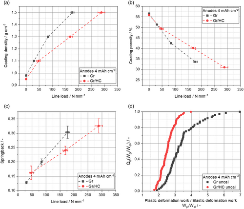
It is noticeable here that the HC particles feature a more elastic deformation behavior compared with the Gr particles (Figure 2d), leading to higher line loads overall for the Gr/HC blend anodes compared with Gr anodes to achieve the same coating density, as shown in Figure 2a. The springback of the anodes (Figure 2c), which was determined according to Diener et al.,[22] negatively affects the coating by decreasing the desired coating density and causing stress to the particle binder network, which can lead to a loss in stability. Overall, a higher springback for higher line loads can be observed. As expected, the Gr/HC blend anodes show a higher springback than the Gr anodes due to their more elastic behavior.
The coating porosity (Figure 2b) strongly decreases for both the Gr and Gr/HC anodes while calendering due to the reduction of layer thickness.
3.2 Electrode Structure
Cross-sectional SEM images of Gr/HC anodes at different calendering densities are shown in Figure 3.
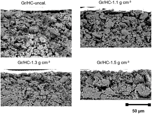
First of all, a significant reduction in layer thickness (see Table 3) results from calendering. With increasing compaction, there are fewer interspaces and an overall denser layer can be observed. It appears that at very high densities (1.5 g cm−3), a more uneven coating structure with many damages and detachments in the layer is found. For the calendering of HC, significantly higher line loads are apparent compared with pure Gr anodes. Thereby, it seems reasonable to assume that at very high densities such as 1.5 g cm−3, a densification front builds up, which leads to a more unevenly compacted electrode with higher densities at the top and bottom. Furthermore, the occurrence of particle fractures due to calendering is possible.
3.3 Mechanical and Electrical Properties
The adhesive strength is used to evaluate the robustness and stability of the anode. Among others, cohesion and adhesion are described here. Cohesion refers to the layer cohesion within the coating, while adhesion refers to the cohesion between the coating and the current collector. It is particularly important to consider the volume increase of the active material during lithiation and delithiation as the anode is exposed to significant stress during cyclization. However, the anode is also subjected to mechanical stress during earlier process steps in the production process such as coiling, cutting, or calendering of the anode.[25]
The adhesive strength of Gr anodes, as well as Gr/HC blend anodes as a function of the calendering densities is shown in Figure 4a.
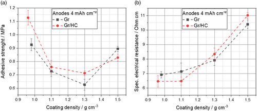
For both the blend anodes and the Gr anode, the adhesive strength decreases initially with increasing density as the stress of the calendering causes a loss of contact between the particles of the coating and the current collector as well as to each other in the coating by breaking up the bonds between the particles through the shear forces active during calendering. After an initial decrease of the adhesive strength, an increase of the adhesive strength can be observed at higher calendering degrees caused by pressing the active material particles into the current collector and the formation of new particle bonds. This phenomenon during calendering is similar to that observed by Meyer et al.[31] It is noticeable here that the adhesive strength of the Gr/HC blend anodes is not as greatly enhanced as in the case of the pure Gr anode with further calendering. These differences can be accounted by the results from the measurements of the deformation behavior of the Gr and Gr/HC anodes (see Figure 3d). Due to the aforementioned more elastic deformation behavior of the HC particles compared with the Gr particles, higher line loads are apparent for the Gr/HC blend anodes. Consequently, the formation of new particle bonds with the current collector at higher calendering forces is impeded, which was also recently shown for silicon/Gr composites by Scheffler et al.[32]
Moreover, it can be observed that blending Gr and HC leads to an overall increase in adhesive strength compared with the pure material of Gr. This can be explained by the distribution of the HC in the blend. The smaller HC particles are positioned between the coarser Gr particles and enabled stronger cohesion in the layer as well as adhesion to the current collector due to the higher surface area and more particle–particle contacts in the blend. Furthermore, the larger surface area also results in a more effective formation of the particle binder network, which leads to an increase in the adhesive strength due to better crosslinking of the particles.
Overall, it can be said that the selected electrode formulation provided a sufficiently high adhesive strength for the further processing of the electrodes for all the compactions both for the blend anodes and for the pure Gr anodes.
The electrical resistance of the anodes indicates possible transport limitations of the electrons during charging. The specific electrical resistance of the different anodes is shown in Figure 4b.
For all the electrodes investigated, an increase in specific electrical resistance with increasing electrode density is observed. The increase in specific electrical resistance with increasing electrode density suggests that the breaking of bonds between particles and current collector during calendering results in an increase of the specific electrical resistance due to the reduction of electrical conduction paths and more particle–particle contact resistances within the same layer height. Furthermore, the specific electrical resistance increases with the addition of HC for small densities, which can be explained by the increased electrical conductivity of HC itself compared to Gr. Here, it is noticeable that with increasing electrode density, the specific electrical resistance of the Gr/HC blend exceeds the specific electrical resistance of the Gr, which can be explained by possible particle fractures of the HC while calendering.
3.4 Pore Size Distribution, Ionic Resistance, and Tortuosity
The electrochemical performance of an LIB is highly dependent on the pore structure of the electrodes, as it determines ion transport. Furthermore, the adjustment of the pore structure provides a possibility to counteract changes in the electrode volume due to lithiation. Therefore, the pore structure of the different anodes was analyzed and is shown in Figure 5a. The electrode porosities measured by mercury intrusion porosimetry can be found in Table S2, Supporting Information.
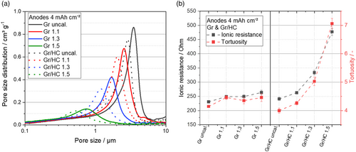
Among other things, smaller pores in the Gr/HC blend anodes can be detected. A bimodal particle size distribution affects the pore structure. Therefore, it seems reasonable to assume that there is a denser packing of the different-sized particles of HC and Gr. The smaller HC particles fill the spaces between the larger Gr particles within the active material mixture, resulting in smaller pores overall for the blend.
As smaller pores are undesirable for fast charging, the ionic resistance and the tortuosity have also to be taken into account. The ionic resistance of the anodes signals possible transport limitations of the lithium ions during lithiation. The higher the ionic resistance, the more limitations can occur during charging and discharging of the anode. If the lithium-diffusion speed does not meet the demands of high charging rates, lithium plating can occur, leading to a deterioration in cycling stability and contributing to safety concerns.[33] Based on the measurements of the ionic resistance, the tortuosity of the electrodes was determined, taking into account the porosity and layer thickness of the electrodes. The tortuosity provides information about the winding of the pores and, thus, can be seen as another indicator for the pore network of the electrode. A reduction in tortuosity has a positive effect on the charging performance of the LiB as the diffusion pathways are shortened, which is one of the most important factors for fast charging.
An overview of the ionic resistance and the tortuosities of the different anodes is shown in Figure 5b. As expected, the ionic resistance increases with the calendering degree of the anode, both for the Gr anode and the Gr/HC blend anodes. Furthermore, it can be observed that the ionic resistance is smaller for the pure Gr anode, as there are larger pores present compared with the blend. For the blend anodes, the difference between the calendering densities is also much more obvious as more small HC particles are pressed into the pores between the Gr particles, which cause the impedance and tortuosity to increase immensely at higher densities.
While the ionic resistances of all the pure Gr anodes are smaller than the resistances of the blends, the tortuosity in the blend anodes is slightly reduced at smaller densities, which can be explained by the porous structure of the HC, through which the length of the diffusion paths of lithium ions can be reduced. These smaller pores are in nanometer range and, thus, below the scale of resolution of the mercury intrusion measurement. The reduction in tortuosity of the Gr/HC blend anodes at moderate densities compared with the Gr anode is beneficial, especially regarding fast charging ability of the anode as it may significantly increase the lithium-diffusion speed.
3.5 Electrochemical Performance and Lithium Plating Analysis
As shown in Figure 6, the capacity retention in the charge rate test for the Gr/HC blend anodes and the Gr anodes as well as the energy density depending on the C-rate of the different anodes can be seen.
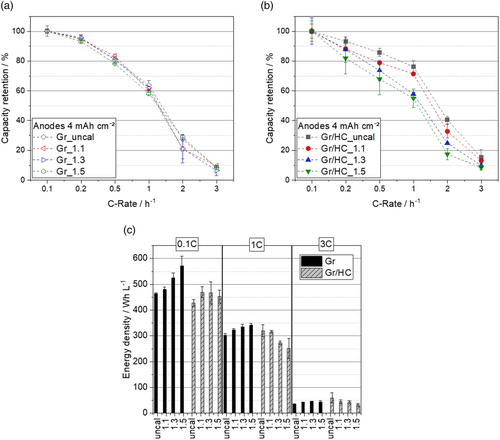
It can be observed that the discrepancy regarding the capacity retention between the different densities of the anodes is more significant for the Gr/HC blend anodes than for the Gr anodes, where the difference is marginal. This is directly related to the high increase in ionic resistance and tortuosity with increasing degree of calendering of the blend anodes. While a larger densification leads to an immense reduction in capacity for the blend anodes, the difference in capacity retention between the differently calendered Gr anodes is not as large.
Furthermore, an increase in capacity retention of the blend anodes compared with the Gr anodes appears only at higher charging rates and only for low electrode densities: For a charging rate of 1C, an increase of ≈10% in capacity retention compared with the best performing pure Gr anode can be observed with the uncalendered blend anode. Here, the degree of calendering seems to be decisive for the advantage of the HC compared with Gr. HC performs better at higher charging rates, as the reduced tortuosity and the associated shorter lithium-diffusion paths due to the interporous structure mentioned earlier come into play.
One aspect that also has to be considered when the density of the anode is varied is the energy density. The combination of a high energy density with a high charging capacity is challenging, as high energy density requires high compression combined with low porosity, which stands in direct contrast to the requirements of a fast charging anode. This work focuses on increasing the rate of lithium-ion diffusion but also aims to illustrate the expenses of the energy density aspect. For the determination of the energy density, which is shown in Figure 6c, the layer thickness of the anode, the cathode, and the separator was taken into account. If one takes a closer look at the energy densities, it can be seen that due to the higher layer thickness of the Gr/HC anodes and due to the smaller initial capacities compared with Gr (initial Coulombic efficiency Gr: ≈79%, initial Coulombic efficiency Gr/HC: ≈72%), a significantly lower energy density can be observed for all the HC anodes at 0.1C. However, due to the higher capacity achieved by the Gr/HC blend anodes at higher charging rates, the energy density at 1C is almost in the same range as the energy density of Gr and, thus, no major sacrifices in energy density are made. This again only applies to the low-density blends. Furthermore, the energy density at 3C of the low-density Gr/HC blend anodes is even slightly higher than the energy densities of the Gr anodes at the same charging rate.
Due to the different performances of the Gr/HC blend anodes and the pure Gr anodes, as well as the different degrees of calendering, it is assumed that alongside the ionic resistance and the reduced tortuosity another possible explanation for the discrepancies in the performance could be the polarization of the anode at higher charging rates resulting in lithium plating. Therefore, the occurrence of lithium plating on selected cells was investigated by an in situ open-circuit voltage (OCV) analysis and postmortem images of the anodes. The lithium plating detection tests were performed at 0 °C. The results for 0.2C and 1C are shown in Figure 7.
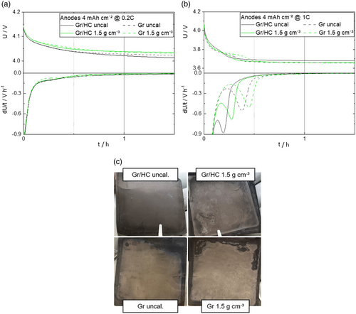
A plateau in the voltage in the relaxation step due to the reintercalation of the metallic lithium and, correspondingly, a peak in the differential voltage curve indicate lithium plating. Based on the results of the lithium plating investigations as shown in Figure 7, it can be concluded that at a C-rate of 0.2C (Figure 7a), no plating is to be detected in all the cells as no voltage plateaus can be observed. At a charging rate of 1C (Figure 7b), lithium plating can be detected in all the cells shown. It can be seen that lithium plating is more pronounced at higher densities, as well as for Gr compared with the Gr/HC blend.
There are different possible explanations for this: On the one hand, the anode potential of HC is significantly higher than that of Gr.[34] Lithium plating occurs when the potential versus lithium drops below 0 V, so that metallic lithium is deposited on the electrode. As the potential of Gr already is significantly lower than the potential of HC, lithium plating is more likely to occur with Gr than with HC. Furthermore, regardless of the active material, more significant lithium plating can be observed at higher densities of the electrode as there is a correlation between lithium plating and the porosity, with a higher porosity leading to less lithium plating.[24] Moreover, the results of the plating analysis could be confirmed in the postmortem images (Figure 7c), where plated metallic lithium is clearly visible, especially on the Gr anodes without HC, and only slight plating could be observed on the Gr/HC blend anodes. Furthermore, the plating here is more pronounced at higher densities, which is in good accordance with the observations made in the lithium plating detection analysis.
4 Conclusion
In this study, a systematic investigation of the effects of HC in Gr/HC blend anodes and the consequences of densification of these anodes at different degrees of calendering on the mechanical, electrical, and structural properties of the anode coating, as well as the electrochemical performance in pouch cells, is presented.
By adding HC to the Gr, it was possible to achieve higher adhesive strengths and lower electrical resistances at moderate densities in comparison with pure Gr anodes. With increasing electrode density, an increase in electrical resistance and also a reduction in adhesive strength could be observed. The addition of HC led to a shift in the pore structure toward smaller pores and, thus, an increase in ionic resistance, but also a reduction in tortuosity, which is related to the interporous structure of the HC. However, this only applies to low coating densities as the availability of the interporous structure is highly dependent on the degree of compression. The turbostratic structure of HC allows faster lithiation at higher C-rates and, thus, a slight increase in capacity retention could be observed. Moreover, the high anode potential of HC prevents lithium plating, which might be the main advantage of HC compared to Gr.
Overall, this study revealed that the performance of Gr/HC blend anodes is largely determined by the calendering compression. Moderate compressions are one way to increase the rate capability, while maintaining the energy density with HC. However, for the further enhancement of energy density, a combination with high-energy materials such as silicon should be considered. Furthermore, the usage of HC and Gr in different particle sizes and ratios in blends is useful, as matching the particle sizes to each other may lead to a more defined pore structure and, thus, better Li diffusion characteristics in the anode coating.
Acknowledgements
The authors gratefully acknowledge the Federal Ministry of Education and Research (BMBF) and “Projektträger Jülich” (PTJ) for giving the base for the demonstrated results within the project “HiStructures” (03XP0243B; TU Braunschweig). They would also thank all the participating colleagues for their valuable assistance as well as all the technicians of the Battery LabFactory for their help in performing the experiments, with special thanks to Stoyan Ivanov as well as Alexander Neuberger for assistance during calendering and coating and Julian Koch for assisting with the cell assembly.
Open Access funding enabled and organized by Projekt DEAL.
Conflict of Interest
The authors declare no conflict of interest.
Open Research
Data Availability Statement
The data that support the findings of this study are available from the corresponding author upon reasonable request.


