Laser-Based Joining of Electrode Stacks for Automated Large-Scale Production of Li-Ion Battery Cells
Abstract
Battery technology is the basis for the electrification of mobility and the key to a sustainable future. Herein, lithium-ion battery (LIB) cells are experiencing increasing demand, especially in the automotive industry. To meet the rising needs, highly productive and cost-efficient processes in battery cell production need to be available. Within the joint project HoLiB—High Throughput Processes in Lithium Ion Battery Manufacturing, a continuous manufacturing process for battery cell production is developed, set up, and evaluated. The aim is to separate, batch, and contact a cell stack within a cycle time of two seconds. The joining of the individual battery electrodes to each other is of particular importance. The process should enable contacting of both electrodes within the specified cycle time, while joining both aluminum and copper in a process-reliable manner. These requirements are met by laser beam welding. The energy input is localized and the fast processing enables the contacting of both materials in a very short time. This article describes the development of laser-based contacting of the electrode stacks with the arrester tabs. For this purpose, three beam sources with “blue”, “green,” and near-infrared wavelengths are tested and evaluated for the joining requirements.
1 Introduction
Increasing productivity in cell manufacturing is a high priority to reduce manufacturing costs and meet the increasing global and national demand for lithium-ion batteries (LIBs) for electromobility.[1, 2] In current cell manufacturing, the interconnection technology of the individual layers of cathodes and anodes is a particular challenge. The HoLiB project aims to develop an automated high-throughput production of LiB that links the sub-processes of fabrication, stack formation, and contacting, that is track-bound, and that has a continuous material flow. Linking the sub-processes promises to minimize non-value-added time components in buffers, reducing cycle time per assembled and stacked electrode to <0.1 s. The individual electrodes produced with a laser-based separation process are deposited in a magazine via a stacking wheel and welded there with a cell arrester tab. An ultrasonic welding process is usually used for this purpose, in which a tool applies contact pressure to the stack of foils and induces vibrations in the component by ultrasound in the kHz range. Friction at the interfaces causes the foils to be welded to each other and to the cell drain tab. When feeding electrode foils with a targeted cycle <0.1 s, the necessary mechanical contact to apply the process force and vibration is a constraint.[3, 4] An alternative process for welding aluminum and copper is laser beam welding. For this, the laser beam is focused on the component surface to melt and weld the material. The feed motion and the positioning of the laser beam on the component can be achieved with precision by using a scanner. What is necessary for welding here is the absence of gaps between the joining partners, but no further pressure.[5] The electrical resistance of the resulting joined connection must be particularly low to ensure the functionality of the individual battery cell over a long period of time. In addition, the formation of weld spatter should be avoided, as this can lead to a short circuit in the cell. These requirements necessitate a comprehensive understanding of the process for laser-based contacting of battery electrode stacks.
2 State of the Art
The joining of electrode stacks for the production of LIB cells is currently mainly carried out using an ultrasonic welding process. Problematic for the process-safe joining of anode and cathode with this method are the high necessary forces and the vibrations and frequencies that act on the electrodes during the process.[6] These high energies can mechanically weaken or severely deform the electrodes.[7] Other limitations include tool wear and the need for accessibility to both sides of the joining partners.
Laser beam welding, in contrast, is a noncontact joining technique that only requires accessibility on one side in the overlap configuration. Two different regimes are considered in laser beam welding: heat conduction welding and deep penetration welding. In heat conduction welding, the material surface is melted and the introduced energy is transported to deeper material layers by heat conduction. In deep welding, the material evaporation temperature is exceeded at the surface, creating a vapor capillary. Within this capillary, the laser radiation is reflected several times, so that the overall absorption in the process is increased.[8] Deep penetration welding produces narrow and deep welds with an aspect ratio of about 10:1. Local power modulation is used to increase the joint width and thus also the current-carrying capacity. In this method, a generally circular oscillating motion is superimposed on the linear feed motion, thus increasing the irradiated area. The heat dissipating into the center of the circle helps melt the material, making the process more efficient.[9] Galvanometric laser scanners are used for this process strategy. Gaps between the joining partners, which can also occur due to thermally induced deformations during the joining process, cause instabilities and irregularities. Clamping technology is therefore of particular importance.
Laser beam welding of copper is a particular challenge due to its material-specific properties. Copper has a high thermal conductivity (394 W m−1 K−1), which causes the absorbed energy to flow rapidly out of the fusion zone. Another factor for a reproducible welding process is reflectance. Spectral analysis is carried out to determine the reflectivity of the materials used. The reflectance at room temperature is ≈95% for a wavelength λ = 1070 nm, which corresponds to that of near-infrared (NIR) fiber lasers. For “green” wavelengths (λ = 515 nm), this value is about 50%, and for “blue” wavelengths (λ = 450 nm), it is about 45%. The values for the materials used here can be taken from Figure 4.
Different wavelengths are being experimented with for the laser-based joining of aluminum and copper foil stacks for battery cell production. For copper, in particular, these beam sources are becoming increasingly relevant. For “green” wavelengths, it has been shown that spatter development is lower compared to NIR welds,[10] but the roughness of the weld surface increases.[11] Furthermore, the achievable process speeds for laser welding with “blue” wavelengths (450 nm) are limited. The characteristics of the welding process and the interaction between wavelength and material properties lead to significantly reduced process speeds compared to NIR processes.[12, 13] Another problem is the high number of interfaces when joining the electrode stacks. Impurities and the resulting oxide layers favor the formation of pores. Particularly in the case of aluminum, strong pore formation can be observed, the size and frequency of which depend on the feed rate and the number of foils.[14] Another defect that occurs particularly with aluminum is foil stripping, which can be observed in the cross-section.[15, 16]
In recent years, several studies have been conducted on the reliable welding of electrode stacks with different beam sources and process approaches.[15-17] Especially considering the modern beam sources in the visible wavelength spectrum compared to established NIR beam sources, reliable comparisons for the application in battery cell manufacturing are missing.
3 Experimental Section
3.1 Cell Format, Foil Stacking, and Sample Preparation
Before the individual cells can be welded in production, they need to be pre-assembled in an upstream stacking process. For the sample battery cell used here, 20 anodes (copper) and 20 cathode foils (aluminum) each were used. Separators were placed between the individual electrodes. The resulting stack and the simplified exploded view are shown in Figure 1.
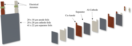
In total, this resulted in a theoretical thickness of 1.502 mm for the foil stack consisting of the three components. For the parameter study described here, a simplified geometry of rectangular folded foils was used hat roughly corresponds to the geometries of the arrester tab. This has the advantages of preventing material waste, reducing the preparation time of the individual layers for the welding process, and an easier implementation of a preliminary clamping device.
3.2 Preliminary Pneumatic Clamping Device
For process-safe laser beam microwelding of electrode stacks on arrester tabs, a clamping device is needed that meets the requirements of the process. These include, for example, a process cycle time of <2 s seconds, the achievement of a high degree of automation, and the ability to combine the clamping with a laser beam welding system. Due to the low inherent stiffness of the thin metallic foils and the residual stresses induced by the rolling and winding process during production, homogeneous pressing of the foils is also essential. Otherwise, thermally induced effects can occur like bulging or decoupling of the stack system up to single foils resulting in different thermal masses of the sub-systems, which have a negative impact on the heat conduction during the contacting process. Accordingly, a clamping device must be provided which makes the necessary joining force available, takes the above-mentioned requirements into account, and can be transferred to a linear production process. Various clamping strategies for laser-based joining are available for generating a contact force on the foil stack. These can be divided into mechanical, pneumatic, hydraulic, or magnetic principles. To meet these requirements, a clamping device with a pneumatic contact pressure principle was designed and manufactured. Figure 2 shows the preliminary clamping device, which is used in the welding experiments.
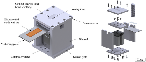
The smaller electrode formats were pre-positioned on a plate which was inserted into the device afterward. By applying a pressure of up to 6 bar to the double-acting compact cylinder, a relative movement was realized to generate the contact pressure. The counterpart to the contact pressure was the press-on mask, which has a milled-out area through which the laser beam hits the positioned foils. To prevent bending of the mask, the thickness of the mask was confirmed by simulation of the occurring forces.
3.3 Laser Beam Sources Setup
For the laser beam welding tests with a wavelength λ of 450 nm, the LDMblue 1000-40 with the OTS 5 focusing optics from the company Laserline was used. The maximum output power is 1000 W. The relative movement between the clamping device and the laser beam to enable the welding process is realized by an SMC linear axis, which can reach a maximum feed rate v of 300 mm s−1. In addition, a crossjet is used to keep possible spatter or process vapors away from the protective glass of the optics. This minimizes possible damage to the optics. The setup is shown in Figure 3, section A.
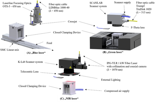
The system in Figure 3, section B, includes a disk laser of a laser wavelength λ = 515 nm. Within the scope of this work, the system is adapted so that the clamping device for joining the foil stacks is positioned centrally underneath the focusing lens. In contrast to the previously described system, the feed motion was implemented by a beam deflection system from SCANLAB called “hurrySCAN 30.” The laser radiation with a wavelength of 515 nm is provided by the TruDisk 1020 from TRUMPF, transported to the scanner via a fiber and enables welding tasks with a power of up to 1 kW. The caustic measurement showed that the focusing lens (LINOS F-Theta Ronar f160) achieved a focal diameter of 162 μm with an M2 of 26. In addition, the system was also equipped with a crossjet to reduce possible damage to the optics.
The third setup was equipped with an IPG-YLR 1 kW fiber laser, with a wavelength of λ = 1070 nm. For process monitoring, a camera was installed coaxially in the beam path. Similar to the system using a green disk laser, the laser beam was deflected by a galvanometric scanner system (K-Lab Laser & Control, Gunpo-Si, Korea) before the radiation is focused by a telecentric lens (see in Figure 3, section C). The clamping device was pre-positioned below the scanner system. The fine adjustment of the weld seam position was carried out via the software, in which the parameters for the laser power and the feed rate were also transferred. The caustic measurement showed that, in comparison, the smallest focal diameter of 28 μm was achieved with a diffraction index M2 = 1.58 with this system.
To determine the interaction of the materials used with the laser wavelengths of the specified setups, a spectral analysis was performed in the Lambda UV–vis–NIR spectrometer. The result is shown in Figure 4.
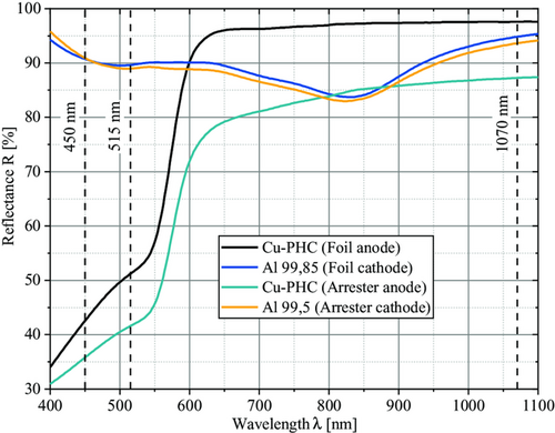
Although the material designations of the copper electrode materials were identical, deviations in the curves were due to different surface conditions of the materials. Based on the values, it was clear why beam sources in the visible wavelength range were becoming increasingly relevant for the processing of copper. For example, if the beam sources at a wavelength of 1070 and 450 nm were compared when processing Cu-PHC (black graph), the reflection reduced from 97% to 43%. When this value, neglecting transmissive effects, was converted into absorption, about 57% of the energy of the “blue” laser radiation was initially absorbed by the material. In the case of “green” laser radiation (515 nm), 48% was still initially absorbed, while this value for NIR radiation sources (fiber laser, 1070 nm) was only 3%. Since the reflection or absorption of laser wavelengths in the material depends on the material temperature, the values given here changed during the process.
The three systems allow different approaches to be taken into account when elaborating a welding strategy. To provide a better overview of the systems characteristics, important properties of the systems are listed in the following table (Table 1).
| Setup characteristics | Diode laser | Disk laser | Fiber laser |
|---|---|---|---|
| Wavelength λ | 450 nm | 515 nm | 1070 nm |
| Max. Power P | 1000 W | 1000 W | 1000 W |
| Beam shape | Gauß | Tophat | Gauß |
| Diffraction Index M2 | 171 | 25,6 | 1,58 |
| Rayleigh length zR | 0,9 mm | 1,5 mm | 0,4 mm |
| Focusing Optics | Laserline OTS 5 | LINOS F-Theta Ronar, f160 (SN 12 464 177) | F-Theta Lens (f163) |
| Focal diameter d | 294 μm | 162 μm | 28 μm |
| Realization of feed rate | SMC Linear axis (vmax = 300 mm s−1) | SCANLAB hurryScan 30 SN: 75 286 | K-Lab Scanner |
| Use of spatial power modulation | no | no | Yes |
The different designs of the systems resulted in widely varying beam qualities, so that welding tests generated with state-of-the-art lasers as well as novel laser beam sources can be shown in the following results.
4 Results and Discussion
For the evaluation of the beam sources with regard to the joining process of the foil stacks with the arrester tabs, comprehensive parameter studies are carried out, which are shown here in detail. The used materials are introduced in chapter 3. First, the weld seam is assessed by visual observation of the seam top bead and back of the sheet, and the adhesion of the foils to the sheet and the quality of the seam are evaluated. If several seam defects are observed despite a bond between the joining partners, the welds are classified as damaged. Welds are in turn characterized as a defect, if there is no adhesion of the foils to the arrester or if hole formation is observed. Figure 5 shows examples to illustrate the classification into the categories. Weld tests are then selected and analyzed metallographically.

4.1 Determination of the Parameter Range and Welding Results
4.1.1 Blue Diode Laser
The results of the tests with the blue diode laser are shown in Figure 6. For this purpose, graphs are generated for copper and aluminum in the form of heatmaps, which show the target power Ptarget on the abscissa axis and the feed rate v on the ordinate axis. The color coding visualizes the areas in which suitable parameter spaces can be found. To be able to make a more reliable statement about certain parameters, certain welds in the suitable parameter space are repeated at least three times (star symbol), whereas welds that do not meet the requirements are only welded once (circle symbol).
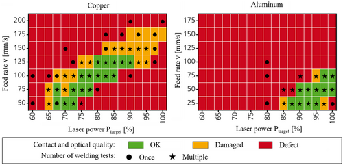
When comparing the two heat maps from Figure 6, it can be seen that a larger process window results for the copper material. This is due to the fact that the absorption of the copper material at a wavelength of 450 nm is more than a factor of 5 greater than for the aluminum material (see Figure 7) and the thickness of the copper stack to be penetrated by the laser beam is less than for the aluminum stack. Accordingly, a higher line energy is required for welding through aluminum. Due to the given focus diameter and maximum power, lower feed rates have to be used to achieve contacting, which has a negative impact on the efficiency of the process. However, the matrices can only give an indication of the visual quality of the weld. Although contacting of the foils takes place in the green-marked area of the matrices, irregularities can be seen on top of the weld seam (see Figure 7). These irregularities result from the low inherent stiffness of the foils and the thermal effect induced by the laser with simultaneous firm clamping at the edge of the foils during the welding process. The irregularities as well as the area of contact pressure can be clearly seen in Figure 7. Furthermore, this problem depends on the large number of interfaces of the foils, which undergo thermally induced bulging and deformation. In addition, cross-sections are shown, which allow a statement about the local bonding.
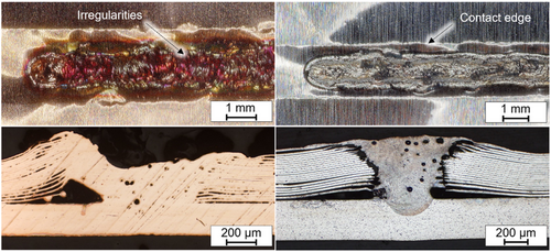
The copper cross-section shows that the melt has bonded all the foils to the arrester tab. However, tests in which the foils are manually pulled off the arrester show that a connection is often only made at certain points. The thermal energy induced in the material by the laser leads to deformations that cause stresses in the component. Due to the fixed limit of the fixture in the edge areas and the stresses induced, the foils can bulge and detach. This results in aperiodic temperature fields in the welding process, which, in addition to the locally changed thermal mass and the inertia of the melt, results in only local bonding areas. In the aluminum section, in contrast, it can be seen that the weld seam is connected to the arrester, but the foils have no connection to the weld seam in the plane of the cross-section. Since the specimens have to be mechanically processed to produce a cross-section, it is reasonable to assume that this processing is the reason for the foils detaching. The homogeneous embedding of the specimens, the variation of the separation process, and the processing by different persons led to the same result, so this can be excluded as a reason for now. Instead, it is assumed that the tearing off is depending on the cooling process. The aluminum material converges to a spherical shape in the molten state to reduce surface stresses. During the solidification process, the material cools, which causes the volume of the melt to reduce. Since the solid foil material is held at the point of clamping, there can be no movement of the foils toward the melt. Ultimately, the foils tear at the edge of the melt pool because the shrinkage process causes the local strength of the hard-rolled aluminum foils to be exceeded. Compared to aluminum, copper has a higher thermal conductivity λth with a simultaneously lower coefficient of thermal expansion αth, but a higher melting point. This would result in locally lower temperatures for copper at equivalent material thicknesses, which in turn affects the thermal expansion of the melt. The lower volume increase and volume decrease at the interfaces between melt and foils of the softer copper material induces lower mechanical stresses than in the case of aluminum. Since the results of strength tests for laser beam welding on copper are unsatisfactory and contacting of the aluminum electrodes can only be performed reliably at very low speeds, this beam source is not suitable for high-speed contacting of battery electrode stacks.
4.1.2 Green Disk Laser
In the following, excerpts of the results for the disk laser emitting in the wavelength range of λ = 515 nm are described. The matrices resulting from the experiments, with at least three repetitions for the parameters with a star symbol, are shown in Figure 8. Similar to the experiments with the blue emitting diode laser, material-specific process windows result. Compared to the other beam sources, the disk laser has a tophat beam profile and the focal diameter of 162 μm is only half as large as in the setup with the diode laser. This results in a higher intensity on the sample surface. Especially with copper, strong weld seam drops can be observed.
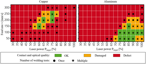
If a weld is examined in its cross-section, which has a visually good weld quality, it is observed that the foils are connected to each other but have no contact with the arrester tab at different points (see Figure 9). This is again due to the irregular contact along the weld. The second similarity to the previous experiments can be seen in the experimental matrix of the aluminum material. Although the beam source with the smaller focal diameter provides a higher average intensity on the material, the maximum laser power of up to 1 kW is a limiting factor. This allows maximum feed rates of v = 150 mm s−1 to produce a contacted foil stack of sufficient seam quality.

However, if the cross-section of a weld is examined in more detail, it becomes apparent that the foils also detach from the weld here. It is assumed that the same thermal and mechanical effects are responsible for this as described in the previous tests. Pores and seam defects are also evident. The poor contacting results for laser beam welding of the copper stacks as well as the low absorption of the laser radiation on aluminum and the resulting low possible feed rates in the process disqualify this beam source for electrode stack contacting under high speed.
4.1.3 NIR Fiber Laser
In the third step, the previously described experiments are performed with the fiber laser setup (λ = 1070 nm) with the same number of repetitions for the star symbols as described before. In addition, the welding strategy of spatial power modulation is applied to achieve the largest possible bond width with a small focal diameter of 28 μm. The experimental matrices of the welding tests are shown in Figure 10.
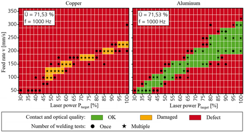
Looking at the heat map for the copper welding tests, it can be seen that no parameter meets the requirements for good seam quality, but parameter ranges exist where the foils are contacted to the arrester tab but have a lower seam quality. This is due to the fact that especially with the 10 μm thick copper foils, cutting of the foils can occur during processing as a result of the high intensity. Because of the high intensity and low thermal mass of individual foils, the evaporation temperature in the uppermost foils is reached instantaneously. This process regime is similar to cutting or ablation. Nevertheless, similar results can be achieved at high speeds, so that the described “cutting effect” can be prevented if the optical setup is modified to reduce the intensity at the workpiece. This can be achieved by replacing the focusing lens so that the resulting focus diameter is increased. An alternative is to adjust the parameters of the local power modulation to distribute the energy supplied to the welding zone over a larger area.
In the test matrix for the aluminum material, a large parameter space can be seen in which visually good welds are possible. Compared to the other beam sources, a significantly larger process window results here, since the small spot diameter of 28 μm allows significantly higher intensities to be achieved and thus higher feed rates can be realized with low laser power. Figure 11 shows two cross-sections that differ in terms of their power and feed rate.

In the left cross-section, the foils can again be seen detaching from the weld seam, which is indicative of the effect already described. In the right section, it is shown that a larger area has melted and part of the foils are connected to the arrester. However, where the foils are not connected to the arrester, it can be noticed that the arrester material is melted locally and fused with the melt of the foils. Furthermore, it can be observed that on the left and right sides, the melt on the foils has solidified and no breakaway can be identified. Unlike the welds with linear feed or oscillation strategies with a small oscillation amplitude, in which the laser beam moves centrally in the melt, with sufficiently large melt pools the effect is that the laser beam creates a circulating melt pool. The melt moves behind the laser beam as a function of the path movement. Due to a material deficit and the movement of the melt at the edges, the melt solidifies at the foils, resulting in voids and larger pores in the center of the weld. When laser welding the electrode stacks with a fiber laser, large process windows can be identified for the aluminum side and high joining speeds are achieved. The observed film breakage persists and is most likely due to the material. Since this effect cannot be reduced or eliminated by the choice of beam source, other process strategies must be selected to achieve a process-reliable joint. For laser beam welding of the copper side, the fiber laser in its current configuration is suitable to a limited extent. One beneficial aspect of high-speed contacting is the possibility of achieving a connection between the foil stack and the arrester tab even at high feed rates (v > 200 mm s−1). An electrical examination of the connection can provide information about the actual quality here. In addition, it is possible to adjust the optical setup, adapt the joining strategy, or select other process parameters for local power modulation. In the experiments shown here, only a circular oscillation is used, which is superimposed on the linear feed motion. Other geometries are also imaginable, which lead to adapted melt pool dynamics and prevent the separation of the uppermost foils. In summary, the use of a fiber laser shows the greatest potential to enable process-reliable contacting of the foil stacks at high speed.
4.2 Development of the Clamping Device for the Electrode Format Based on the Results
Based on the knowledge gained in the welding tests about improvements for the clamping device, a new design is introduced that takes these requirements into account and addresses the final electrode format. Therefore, the design process is adapted according to VDI 2221 to use a standardized problem-solving systematic.[18] To determine functions and their structures, VDI 2221 provides the function structure. This is intended to promote understanding of the task and make aspects of the subtasks clear.
For the main task of joining the electrode foils to the arresters, the welding process must first and foremost be enabled by ensuring the accessibility of the laser beam to the joining location and taking the incoming and outgoing heat flows into account. Materials with low thermal conductivity should be selected for the clamping device so that the energy deposited in the workpiece by the laser beam does not dissipate into the surrounding materials. Surrounding elements made of highly thermally conductive metals such as copper result in higher necessary energy input to produce the same welding result. At the arrester tabs, a reproducible connection width is essential to secure constant electrical properties to avoid voltage fluctuations and minimize the described thermal effects. The reproducibility of the welding result is also coupled to the positioning and the homogeneous clamping of the foils to avoid varying heat transfer effects. To realize a required process cycle time of <2 s for each battery cell, high welding speeds and short non-productive times are needed. To compensate for the higher welding speed, more laser power is required. At the same time, the process is less reproducible because there is a greater potential for error due to the inertia and low inherent stiffness of the foils during positioning in the joining device. Finally, as the last task in the functional structure, economic efficiency should be considered. On the one hand, the wear of the components should be reduced to avoid maintenance costs. Furthermore, there should be the possibility to implement an automated control process in line or in situ. All these observations from the first welding tests result in challenges for the improved clamping device. The improvements listed in Table 2 are intended to address these challenges like the dominating necessity of homogenous clamping of the thin metallic foils to maintain a constant thermal mass during the welding process.
| Challenges | Improvements | Expected effects |
|---|---|---|
| Positionability of the electrodes and arresters on the positioning plate | Modular plug-in system via dowel pin connection (screw connection possible) | More accurate positioning of materials from outside the clamping device |
| Low contact pressure due to large-area force application | Use of local material increases (contact pressure lips) | Force application via a smaller cross-section to increase contact pressure |
| Welding on the carrier plate | Groove as a beam trap in the lower contact partner | Less wear, avoidance of dead times |
| Deflection of the clamping device | Increasing of material thickness | Reduction of translation to a few micrometers |
| Process-induced wear of the clamping device | Replaceable inserts in the joining area | Reduced maintenance effort, reduction of interfering variables |
| Statement about best possible construction material not possible | Replaceable inserts in the joining area | Wirtschaftlichen Anpassung der Vorrichtung |
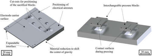
Based on these considerations and an assessment of risks in the welding process, the two main elements were identified. These two main elements are the positioning unit for the electrodes and the contact pressure mask in combination with interchangeable elements as shown in Figure 12. In detail, they are responsible for ensuring that the materials can be positioned reproducibly and pressed on homogenously during the welding process. This is intended to minimize the bulging of the individual foil layers, at least before the welding, by applying a more localized contact pressure through the contact pressure lips of the interchangeable elements. Even if the clamping components in the weld area are damaged, they can be replaced efficiently to reduce maintenance costs.
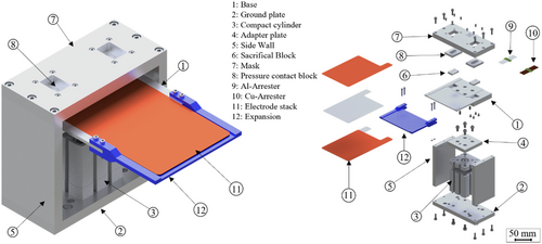
Finally, the overall design is shown in Figure 13 in the form of an exploded view. Excluding the electrode materials and the screws, the clamping device consists of a base plate, two side walls, a double-acting compact cylinder, an adapter plate, the base, the mask, a 3D-printed extension, and two sacrificial and contact pressure blocks each.
4.3 Alternative Joining Arrangements
The test series show that the main problems in joining the foils on an arrester tab are homogeneous contact along the seam and the melt collapse due to the filling of possible gaps between the individual foils. To compensate for the resulting deficit of the melt, a stack configuration is used for an alternative joining arrangement in which the thin metallic foils are clamped between two arrester tabs. This material arrangement will be referred to as “sandwich configuration” in the following and will be investigated on the setup with a fiber laser. The experimental results shown previously indicate that the maximum output power of the disk laser and the diode laser would not be sufficient to melt the additional material. Two transverse sections for copper and aluminum welded in the sandwich configuration using local power modulation are shown in Figure 14.
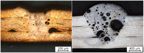
The specimens welded in the sandwich configuration are characterized by the fact that many pores can be seen, especially in the aluminum material, but the foils have a connection to the melt and thus to the arrester compared to the other joining configuration. Furthermore, the upper arrester acts as a material supplier for the material lost due to the dissolution of air inclusions between the foils, so that a sufficient amount of melt is available to bond the joining partners together. Measurement of the surface of the specimens in the sandwich configuration shows that a rough seam surface is produced, characterized by seam bulging and seam indentation, which are probably due to degassing, the heterogeneous melting process, and the many interfaces. When the copper stacks are laser welded in the sandwich configuration, fewer pores are visible in the cross-section and the bonding among the seam, foils, and the arrester sheets is very good. Thus, from a joining point of view, the sandwich configuration is a very good alternative to the conventional configuration. However, the influence of the pores on the aluminum side on the electrical conductivity still has to be verified.
5 Summary and Conclusion
In this work, experiments on laser beam microwelding of copper and aluminum electrode foils on arrester tabs were conducted to advance the further development of a highly automated joining process for the manufacturing of LIB cells. In particular, laser beam sources in the wavelength ranges of 450, 515, and 1070 nm were investigated with regard to their suitability for joining the thin metallic foils with the given preliminary clamping configuration. The results were then visualized in heat maps to narrow down the respective parameter spaces with respect to laser power and feed rate for the three systems and also spatial power modulation for the λ = 1070 nm laser beam source. The results of the investigations are as follows: 1) For the systems with wavelengths of 450 and 515 nm, parameter spaces could be identified that visually show a good weld seam for both materials. 2) Due to the energy input of only up to 1 kW on relatively large beam diameters for both systems, the feed rate has to be reduced, which is a strong limiting factor for high-speed processing. 3) In all three test setups, the foils were found to have torn away from the weld when processing aluminum. This is probably due to the cooling process in combination with thermal deformation and induced surface stresses. 4) When laser welding the copper foils with λ = 1070 nm and a spot diameter of 28 μm, the effect of cutting the foils was observed more intensively. This is due to the strong focus of the laser beam on the workpiece surface. Therefore, spatial power modulation was also investigated to apply the energy to a larger area. 5) To avoid delamination, thermal deformation, or cutting of the foils, more promising results were obtained when using the sandwich configuration for both materials. Since the material thickness increased and the process was already at its laser power limits with the beam sources in the visible wavelength regime, the fiber laser setup with spatial power modulation was used. However, a strongly increased weld height and pore formation were detected when contacting aluminum. To what degree this is acceptable, electrical tests must be performed to characterize the weld seam resistance.
These results complement, support, and extend de Bono's studies. In de Bono's work, aluminum and copper foil stacks were joined with a NIR single-mode fiber laser. Ten aluminum foils could be joined with a minimum single-layer thickness of 100 μm. Thinner foils also showed peeling of the foils and the appearance of pores. Copper foils, in contrast, could be joined down to a minimum thickness of 17 μm and a total number of 30. This publication complements the above-mentioned studies using two additional wavelengths and beam source types. The single-layer thickness of the copper and aluminum foils is once again below the configuration considered by de Bono, so the parameter range considered is extended.
Additionally, the clamping device was improved on the basis of the laser welding experiments and the target cell format for the implementation in a highly automated process following VDI 2221. In further experiments, the clamping device will be optimized step by step to meet the process challenges identified in this work. Furthermore, as beam sources in the visible wavelength range continue to improve, beam sources will soon be available for investigations that provide an output power of at least 1.8 kW at a wavelength of 450 nm. This is expected to shift the process window to higher feed rates. Also, spatial power modulation will be investigated with laser beam sources in the visible wavelength regime.
Acknowledgements
The HoLiB project (Grant no. 03XP0236A) is funded by the German Federal Ministry of Education and Research (BMBF) in connection with the competence cluster for battery cell production “ProZell.” Additional experiments with laser beam sources in the visible wavelength range and metallographic analysis were carried out at RWTH Aachen University within the framework of the Collaborative Research Centre SFB-1120-236616214 “Bauteilpräzision durch Beherrschung von Schmelze und Erstarrung in Produktionsprozessen” and funded by the Deutsche Forschungsgemeinschaft e.V. (DFG, German Research Foundation). The sponsorship and support are gratefully acknowledged. The affiliation of C.S. and A.G. has been corrected on 11 May 2023, after initial online publication of the Version of Record.
Open Access funding enabled and organized by Projekt DEAL.
Conflict of Interest
The authors declare no conflict of interest.
Open Research
Data Availability Statement
The data that support the findings of this study are available from the corresponding author upon reasonable request.


