A Comprehensive Review of Material Flow in FSW/FSP: Experimental Insights and Simulation Perspectives
ABSTRACT
The investigation of material flow in friction stir welding (FSW) is regarded as essential for enhancing the understanding of the processes that influence the quality and structural integrity of welded joints. Critical factors such as microstructural refinement and the resultant mechanical properties of the weld are governed by material flow, which ultimately determines the performance and durability of the joint. This knowledge is deemed crucial for the identification and mitigation of potential defects that can compromise weld strength. Furthermore, a comprehensive understanding of material flow facilitates the optimization of tool design and welding parameters, thereby improving the efficiency and applicability of FSW across various manufacturing contexts. In this review, material flow during FSW is systematically investigated, beginning with an overview of the methodologies employed to study this phenomenon. Subsequently, the dynamics of material flow during FSW are examined, including the interactions between the tool and the workpieces, the filling cavity process, defect formation, and the various parameters influencing material flow. Finally, material flow in novel variants of FSW, specifically Bobbin Tool Friction Stir Welding and Stationary shoulder Friction Stir Welding, is discussed, highlighting their unique characteristics and implications for future research and application.
Abbreviations
-
- AI
-
- artificial intelligence
-
- ANN
-
- artificial neural network
-
- AS
-
- advancing side
-
- ALE
-
- arbitrary Lagrangian–Eulerian
-
- BM
-
- base material
-
- BTFSW
-
- Bobbin Tool Friction Stir Welding
-
- CFD
-
- computational fluid dynamics
-
- CSM
-
- computational solid mechanics
-
- CFSW
-
- conventional friction stir welding
-
- CEL
-
- coupled Eulerian–Lagrangian Method
-
- FE
-
- finite element
-
- FFT
-
- fast Fourier transform
-
- FSLW
-
- friction stir lap welding
-
- FSP
-
- friction stir processing
-
- FSSW
-
- friction stir spot welding
-
- FSW
-
- friction stir welding
-
- HAZ
-
- heat-affected zone
-
- HVZ
-
- high-velocity zone
-
- IMC
-
- intermetallic compound
-
- LoP
-
- lack of penetration
-
- LHT
-
- left-hand thread
-
- ML
-
- machine learning
-
- MSF
-
- mass scaling factor
-
- MFZ
-
- material flow zone
-
- PIV
-
- particle image velocimetry
-
- PAZ
-
- pin-affected zone
-
- PMMA
-
- polymethyl methacrylate
-
- RS
-
- retreating side
-
- RHT
-
- right-hand thread
-
- SAZ
-
- shoulder-affected zone
-
- SSFSW
-
- stationary shoulder friction stir welding
-
- SVM
-
- support vector machines
-
- SZ
-
- stir zone
-
- PVC
-
- transparent polyvinyl chloride
-
- USSFSW
-
- underwater SSFSW
1 Introduction
Friction stir welding (FSW) is an innovative solid-state joining technology that has revolutionized the fabrication of various advanced materials since its patent in 1991 [1-7]. The process is characterized by a unique tool composition consisting of a non-consumable shoulder and a pin designed to create a high-quality weld without melting the base materials, thus minimizing energy consumption and avoiding hazardous emissions [8-13]. As FSW continues gaining traction across multiple industries, understanding the intricate material flow dynamics during the welding process has become increasingly essential to ensuring optimal weld quality and performance.
The study of material flow during FSW is essential for optimizing the welding process and ensuring the quality of the welded joints [14-17]. Understanding how materials flow during welding helps to elucidate the mechanisms of deformation and mixing at the joint interface, which directly impacts the mechanical properties of the weld. Effective material flow is critical in tailoring process parameters such as tool geometry [18-20], rotational speed, and traverse speed for different materials, as inappropriate flow can lead to defects such as voids. The connection between material flow and microstructural evolution is another crucial aspect, as it influences grain refinement and mechanical performance [21-23]. Consequently, studying material flow enhances the quality and strength of welded joints and broadens the practical applications of FSW across various industries.
This review aims to systematically compile and present current experimental investigations into material flow in FSW and Friction Stir Processing while also discussing simulation perspectives that can enhance our understanding of these intricate dynamics. By identifying existing knowledge gaps and proposing future research avenues, the authors intend to foster an environment conducive to innovation and improved practices within the realm of FSW.
In this review, the phenomenon of material flow during FSW is meticulously analyzed, starting with a detailed overview of the diverse methodologies employed to investigate this critical aspect of welding technology. Two predominant approaches are typically employed to examine the flow of material throughout the welding process: experimental and numerical methods, which will be analyzed in detail. The discussion delves into the intricate dynamics of material flow, emphasizing the essential interactions that occur between the welding tool and the workpieces involved. Key processes such as the filling cavity mechanism are thoroughly examined, alongside an exploration of defect formation, where various issues are addressed. Furthermore, the review identifies and elaborates on multiple factors that significantly influence material flow, including the design of the welding tool, rotational speeds, traverse speed, and tilt angle. In addition to conventional FSW techniques, the review also features an insightful discussion on more advanced variants such as BTFSW and SSFSW. These innovative methods are assessed in terms of their unique functionalities and the distinct characteristics they introduce to the material flow process, thereby underscoring their relevance for future research and practical applications in the welding industry.
2 Material Flow Investigation Methods
Material flow investigation is significant for understanding the welding mechanisms that impact the quality and characteristics of joints in FSW. Various experimental methods are employed to analyze these dynamics, with one common approach being the tracer technique [24-28] (Figure 1). This method uses markers embedded in the base materials to visualize and study the flow patterns created during welding. By observing how these markers interact and mix, researchers gain insights into material behavior and the effectiveness of the stirring action facilitated by the FSW tool.
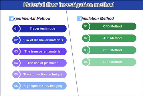
Another effective experimental method involves flow visualization techniques applied to dissimilar materials, such as welding aluminum to steel. This technique highlights how different materials behave during the FSW process, shedding light on interfacial mixing and mechanical properties. Additionally, utilizing transparent material allows researchers to use high-speed imaging to capture real-time flow characteristics, thus providing a clearer perspective on the dynamic processes at work during welding operations [29].
The use of plasticine offers a simplified method for visualizing material flow in FSW experiments [30]. This analog material's distinctive patterns help illustrate how material dynamics change during welding, providing an accessible means to visualize complex interactions. The stop-action technique also assists in this understanding by freezing the deformation field, allowing for an analysis of material flow patterns at specific welding moments, thereby giving insights into effective welding practices [31-34].
Incorporating simulation approaches complements experimental methods, with techniques such as the Arbitrary Lagrangian–Eulerian, Computational Fluid Dynamics, and Coupled Eulerian–Lagrangian methods offering a robust framework for modeling material flow. These methods allow researchers to simulate regions with significant deformation accurately and enhance the understanding of material behaviors to predict flow characteristics under various conditions.
2.1 Experimental Method
2.1.1 Tracer Technique
The utilization of tracer particles for investigating material flow during FSW provides a pivotal method for understanding the intricate behaviors of materials under welding conditions. Tracer particles, which are carefully selected to mimic the physical properties of the base material, serve to visually and quantitatively track the flow paths of the material as it undergoes deformation. Various marker materials have been utilized to monitor material flow during FSW, including aluminum alloys that etch distinctively compared to the base metal, small steel shots, copper foil, and tungsten wire.
The material flow of FSW 6061 aluminum was investigated using 0.1 mm high-purity copper foil as a tracer [35]. Once a stable weld was established, the rotation of the pin and the translation of the specimen were manually halted, resulting in the pin being embedded within the workpiece. After etching, plan view and transverse metallographic sections were analyzed. The microstructural examinations led to the conclusion that material was displaced around the pin during FSW.
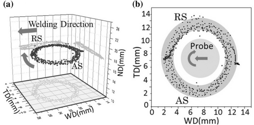
Employing a tungsten tracer, material flow was visualized in three dimensions [36]. This visualization technique relies on tracking the path of the tungsten tracer as observed by two pairs of x-ray transmission systems equipped with real-time imaging capabilities. Figure 2 presents a three-dimensional graph depicting the material flow and its corresponding two-dimensional representation on the welding direction–transverse direction plane. In this context, WD denotes the welding direction, while TD refers to the transverse direction of the plate. The findings from the three-dimensional visualization indicate that the material flow forms a flow zone characterized by concentric circles with a relatively large diameter surrounding the pin (Figure 2). Furthermore, it was observed that the vertical movement of the tracer is negligible under the specific conditions of this FSW process.
An artificially thickened oxide layer was utilized as a tracer material to investigate the material flow and defect formation, with a particular focus on the kissing bond defects occurring at the bottom of the stir zone [37]. In another study, a 0.1 mm thick copper tracer was employed to study material flow during the FSW of 6061 aluminum [38]. It was observed that the shape of the threads in the rotational zone led to significant vertical movements of the material. However, the thermo-mechanical properties and density of the tracer materials utilized in these studies were found to differ considerably from those of the base material, which may result in findings that do not accurately reflect actual material flow.
In another investigation, low-carbon steel slices were employed as tracer materials for FSW of 304 L austenitic stainless steels [39]. It was proposed that the materials would rotate around the pin and deposit at the same transverse position as their initial placement; however, the excessive volume fraction of tracer material hindered the ability to capture precise flow details of materials within the welded joints across various positions.
The tracer method has proven to be instrumental in uncovering valuable insights regarding material flow during FSW. Employing marker materials enables the visualization of flow patterns and the mixing behavior of metals within the weld zone. However, the use of marker materials is not without controversy. The insertion of these tracers in the weld line can significantly influence the characteristics of material flow, potentially altering the natural flow dynamics due to the inherent differences in flow characteristics between the marker and the base materials. Therefore, while the tracer method provides essential information about material flow, it is crucial to consider the implications of marker material insertion, as it can complicate the understanding of actual flow phenomena in FSW. The inclusion of tracer materials with similar thermo-mechanical properties and density to the BM is recommended to ensure consistent deformation and flow behavior between the tracer and the base material at elevated temperatures, thereby enhancing the accuracy of flow results.
2.1.2 The Dissimilar Materials
Several studies have employed FSW techniques to visualize the intricate flow phenomena associated with joining dissimilar metals. One investigation focused on the solid-state flow visualization during the friction stir butt welding of 2024 aluminum to 6061 aluminum alloys. This study utilized differential etch contrast to reveal complex residual solid-state flow patterns that occur in the FSW process of dissimilar aluminum alloys [40]. The material flow was characterized as having chaotic and dynamic intercalation microstructures, showcasing notable swirl and vortex-like features.
The flow pattern and mixing behaviors during dissimilar FSW of AA 2024-T3 and AA 7075-T6 were investigated [41]. The study focused on factors such as the genesis of onion rings and the formation of welding defects. Elevated rotational speeds produced a pronounced onion ring-like mixing pattern within the SZ; however, this condition was associated with a decrease in surface integrity. In contrast, slower rotational speeds resulted in improved weld appearance and optimal mechanical performance, albeit with limited mixing. Furthermore, the analysis revealed a non-stable rotational flow within the threads, attributed to the formation of a cavity at the rear of the pin.
Another study seeks to assess the impact of tool axis offset and the relative positioning of materials on the material flow during FSW of the dissimilar aluminum alloys AA7050-T7651 and AA5083-H111 [42]. FSW experiments were conducted by systematically varying the tool axis offset from zero to 1 mm, affecting both the AS and the RS of the weld, where AA7050 was placed at the AS and AA5083 at the RS (Figure 3).
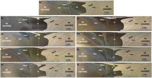
The findings indicate that the tool axis offset significantly influences the material flow pattern within the SZ based on the specified relative positioning of the alloys. When the tool axis is offset toward the AS, the entire SZ is predominantly filled with AA7050 material located on the AS of the joint, as illustrated in Figure 3b–e. In contrast, when the tool axis is shifted toward the AA5083 alloy located at the RS of the joint, the SZ remains primarily dominated by the AA7050 alloy, albeit with an increased concentration of AA5083 alloy in the SZ, as shown in Figure 3f–i. Additionally, it is apparent that at a zero tool axis offset and across all offsets directed toward the RS, the lower section of the SZ on the RS is mainly occupied by the softer AA5083 alloy positioned at the RS.
Visualizing material flow by FSW of dissimilar materials in welding poses several significant challenges when working with metals. First, the use of different alloys in the weld can lead to structural variations compared to a weld made with a uniform material; for instance, the flow of a softer material into a harder one may be impeded. Second, direct observation of flow features in welded sections is impossible, necessitating the labor-intensive process of etching for analysis. Finally, it is often challenging to ascertain whether two different materials have fully blended during welding or merely coexisted in an interlaced manner.
2.1.3 The Transparent Material
The use of transparent materials is an approach to investigate material flow during FSW. These materials, such as specialized polymers, allow researchers to utilize techniques like high-speed cameras and Particle Image Velocimetry to observe internal flow dynamics in real time, which would remain concealed in traditional opaque materials.
Transparent polycarbonate materials were utilized to examine material flow during FSW, owing to their capacity for facilitating visualization of this flow [11]. Observations indicated some general flow characteristics of aluminum during the polycarbonate welding process. However, the implementation of a threaded tool for welding was unsuccessful due to clogging of the threads with the polymer. Additionally, the edge entry of the tool yielded suboptimal weld results.
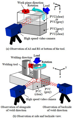
Transparent polyvinyl chloride materials were used to study material flow utilizing a high-speed video camera [43]. Transparent PVC was employed for direct observation, while gray PVC was the tracer material during welding. The flow of material on both the advancing and retreating sides of the pin was observed from the bottom of the tool. Moreover, the material flows were analyzed from the side and backside views in relation to the welding direction (Figure 4). Particle image velocimetry was employed as an optical method for fluid visualization to measure material flow during welding. This technique facilitates the collection of instantaneous velocity measurements and has found applications across various flow-related challenges, including analyzing airflow over aircraft wings in wind tunnel experiments and studying vortex formations within prosthetic heart valves.
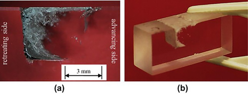
The morphological changes induced by the welding process were examined using transparent polymethyl methacrylate [29]. Figure 5 illustrates the results, presenting two-dimensional (Figure 5a) and three-dimensional (Figure 5b) images of transverse weld samples. Notably, figures reveal significant differences in morphology between the retreating and advancing sides of the welds. The material on the advancing side retains the full transparency characteristics of the base material, with only minor and widely dispersed discontinuities. This observation indicates an almost flawless merging between the adjacent materials and the weld. In contrast, the material on the RS appears completely nontransparent, exhibiting a clear interface between the PAZ and the surrounding material.
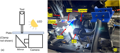
In another investigation, optically transparent polymethyl methacrylate was employed to visualize and quantify the material flow during the FSSW process [44]. To achieve this, tracer particles were strategically placed at the interface between the tool and the material to facilitate the visualization of plastic flow. The PIV algorithm was applied to measure the flow velocity. The imaging setup utilized for the FSW experiments is depicted in Figure 6. This system comprises an LED light source for illumination, a high-speed camera, and a mirror designed to redirect the image from the underside of the base material to the camera. After the video recordings were obtained, the open-source software OpenPIV was utilized to conduct the PIV analysis.
It is important to note that the thermo-mechanical conditions experienced by mentioned transparent materials, including PMMA, PVC, and polycarbonate, during FSW, differ markedly from those encountered during the welding of metals. As such, the results obtained should not be extrapolated to metals due to the distinct material flow mechanisms and the varying morphologies of weld defects that are present in metallic welding processes.
2.1.4 The Use of Plasticine
Plasticine has emerged as an effective medium for modeling the deformation of metals due to its stress–strain behavior being similar to that of metals under conditions of elevated strain rates and temperatures [45]. Moreover, conducting experiments with plasticine is economically feasible, given its low cost. One of the significant advantages of plasticine is its availability in a wide array of colors, enhancing its versatility for flow modeling in various applications. By employing multiple colors of plasticine in welding experiments, researchers can analyze the regions of material mixing and trace the origins of displaced materials. In this context, mixing refers to the joining of two distinct color clays to produce an intermediate composition through the welding process.
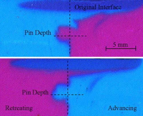
A study focused on the use of plasticine as an analog for modeling material flow during FSW of metals [46]. The technique involves combining different colors of plasticine in the weld to facilitate flow visualization. Figure 7 illustrates cross-sections of cyan and magenta clay used in welds executed with a smooth pin. Notably, these two colors are independent of the weld side, yielding inverted images with only slight variations between them. The analysis reveals that the mixed region situated beneath the shoulder contains approximately 68% advancing material when the magenta clay is placed on the advancing side, while the region shows 74% advancing material when using cyan clay in the same position.
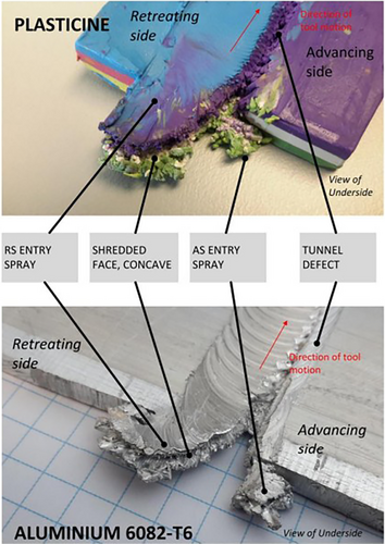
Plasticine sheets were employed in the process of bobbin FSW, yielding structural characteristics that closely mirror those produced in aluminum (Figure 8) [47]. The resulting features exhibited remarkable similarities, particularly the entry sprays observed on both the retreating and advancing sides of the weld. This comparison leads to the conclusion that plasticine effectively replicates the structural anatomy associated with BFSW in aluminum.
2.1.5 The Stop-Action Technique
The sudden “stop action” technique, implemented via an emergency stop, allows for rapid withdrawal of the tool when the FSW machine unexpectedly loses power. This method was used to analyze material flow dynamics in FSW through the use of a thin Cu-40Zn foil, which serves as a marker material embedded into the butting surface of two copper samples [48]. The findings reveal that strain in the SAZ exhibits a distinct stair-step pattern as the material moves from the front to the rear of the tool. This behavior corresponds to two specific stages of material flow: an initial acceleration phase followed by a subsequent deceleration phase. During these stages, a notable phenomenon occurs—strain reversal, which results in a sinusoidal variation of the strain rate. In contrast, the PAZ presents a different behavior, showing no evidence of strain reversal. Instead, this zone is defined by the development of banded structures. Significantly, the average strain rate recorded in this region during the band formation process exceeds the maximum strain rate observed in the SAZ.
The material flow was investigated using a stop-action technique with a thin copper foil serving as a tracer between the surfaces of the aluminum plates [38]. It was observed that the upper third of the plates was primarily affected by the shoulder, which stirred and pushed the material downward. The remaining thickness was influenced by the pin. Furthermore, a threaded pin was utilized, and vertical and vortex motions were reported. Initially, the right-handed thread pushed the material downward, which rotated counterclockwise and was subsequently constrained by the backing plate at the bottom. This constraint compelled the material to move upward, thereby generating the vortex motion.
2.1.6 High-Speed X-Ray Imaging
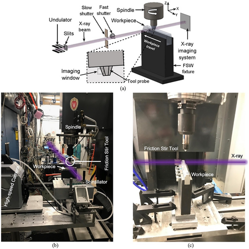
x-ray imaging has traditionally relied on tracer particles, which allow for observing bulk material flow and calculating strain rates. However, a novel approach utilizing in situ dynamic visualization has emerged to capture the material flow dynamics, particularly focusing on density changes such as the formation and closure of cavities around the FSW tool [49]. High-intensity, high-speed x-ray imaging was employed to visualize these material flow dynamics throughout a single revolution of the tool during the welding process.
This imaging technique reveals the filling and formation of voids in the tool wake. The FSW setup was strategically positioned within the beamline hutch, and the x-ray beam was generated employing a periodic undulator, which produces a quasi-single peak. A scintillator system was implemented downstream to convert the x-ray signal into visible light, which was then recorded by a high-speed camera. A schematic representation of the experimental setup is illustrated in Figure 9.
2.2 Simulation Approach
Various published literature has reported considerable numerical work on FSW, which focuses on residual stress, heat transfer, and material flow [50]. Nowadays, the two kinds of thermo-mechanical modeling techniques for numerical simulation, namely computational fluid dynamics [51-53] and computational solid mechanics, are used. Regarding solid mechanics, two main methods, the ALE method [54, 55] and the CEL method [56, 57], have been utilized.
The application of CFD for modeling two-dimensional or three-dimensional metal flow in FSW processes has been documented in systematic publications [58-60]. The primary objective of these studies has been to enhance the understanding of material flow around complex FSW tools while also illustrating the effects of tool rake angle, traverse speed, and rotational speed.
In another investigation, CFD was employed to analyze the influence of different tool shapes on FSW [61]. This algorithm was applied to three distinct tool shapes: cylindrical, threaded, and tap. Velocity and viscosity distributions near the tool, along with flow patterns derived from a particle tracking method, were analyzed to extract the characteristics associated with these tool shapes.
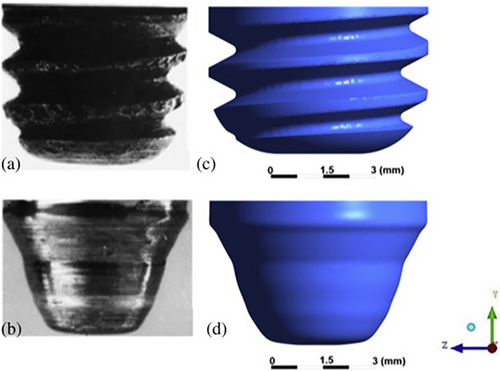
Further research involved the development of a CFD model to replicate the flash formation phenomena occurring during the FSW process [62]. The velocity profile and temperature distribution during welding were predicted using a CFD-based model, providing valuable insights related to slip–stick interface conditions [63]. Additionally, another CFD model was employed to compare flow behavior and deformation zone shape sizes between unworn and worn tool geometries during the FSW process [64]. The comparative analysis gave insights into the impact of tool wear on fluid behavior within the welding zone (Figure 10). The findings regarding strain rate and velocity distribution reveal that a worn tool exhibits diminished stirring action, especially in the vicinity of the weld root. This reduction in stirring effectiveness may contribute to the formation of defective weld joints. Furthermore, observations of the weld zone's shape indicate that when the tool experiences wear, the weld penetration fails to extend to the bottom of the plate, potentially compromising the quality of the resulting weld joint.
Another study focused on developing a CFD-based model to predict tool wear associated with high viscous flow during FSW [65]. Analyses were conducted to evaluate flow patterns during the process and the resulting pressure on the tool surface, utilizing the modified Richard equation to calculate tool wear. Moreover, a CFD code was used to model 3D metal flow in the FSW of AA 2024-T3 aluminum alloy, enabling an investigation into the impact of tool profile on material flow [66]. Scrolled shoulders and threaded pins were utilized as kinematic boundary conditions in the modeling process.
In another research effort, the effect of pin thread on material flow during FSW was analyzed using the CFD approach [67]. Results elucidated three significant influences of the pin thread on material flow. First, the use of pin threads induced accelerated flow velocity and enhanced strain rates, facilitated by preferable interfacial sticking within the thread groove openings. Second, the pin thread trapped material within the high-velocity zones of the thread groove, leading to a multifaceted flow pattern around the threaded pin. Lastly, the pin thread generated a vertical pressure gradient that is crucial for transferring material from the top to the bottom during the FSW process.
A CFD model was also established for dissimilar FSW of 304 stainless steel and 6061-T6 aluminum alloy [68]. A steady-state multi-species transport model was introduced and integrated with a mixture model, enabling the CFD solver to transport species mass fractions of materials effectively. The model successfully characterizes both horizontal and transverse material properties, including the incorporation of embedded steel fragments within the weld, a conclusion that is validated through experimental macrographs. At a rotational speed of 300 rpm, it was determined that steel could not be extruded because of insufficient flow velocity. Conversely, at 600 rpm, steel fragments were observed to mix with the Al6061 matrix. Notably, at higher rotational speeds of 875 rpm and 1200 rpm, continuous steel strips were extruded and deposited within the Al6061 matrix, a phenomenon attributed to enhanced flow velocity and heat generation. Velocity vector analysis revealed a pattern of discontinuous material flow at 300 rpm and 600 rpm, which transitioned to a nearly uniform flow at rotational speeds of 875 rpm and 1200 rpm.
In another study, the CFD simulation was developed to investigate contact states between the tool and the material [69]. It was noted that interfacial sticking states cover extensive areas of the tool-material interface, while significant interfacial sliding occurs at the edge of the shoulder and the lower sections of the pin. This interfacial sticking facilitated the identification of a rotating flow zone beneath the shoulder, which facilitated rapid circular motion. Importantly, the rotating flow zone diameter was found to be smaller than that of the shoulder, a phenomenon related to the interfacial sliding taking place at the edge of the shoulder.
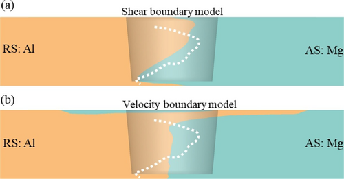
A CFD simulation is utilized to forecast the material behavior during the dissimilar FSW of AZ31B alloy and AA6061 alloy [70]. The analysis reveals that the primary motion involves rotation around the tool pin within the high-velocity zone adjacent to the welding tool. Additionally, there is a vertical velocity component that is less than 10% of the overall velocity. Notably, the material experiences substantial redistribution during the welding process, resulting in the accumulation of the Mg alloy at the lower section and the Al alloy at the upper portion of the joint. Both the shear boundary model and the velocity boundary model were employed separately at the interface between the tool and the workpiece. The predicted Al/Mg interface demonstrates a distorted shape when using the shear boundary model, which is positioned toward the advancing side at the top and the retreating side at the bottom. This trend is corroborated by experimental observations. The shear boundary model accurately predicts the pronounced redistribution of the Mg alloy at the bottom and the predominance of the Al alloy at the upper region (Figure 11a). In contrast, the velocity boundary model suggests an almost vertical configuration of the interface, with only a narrow layer of Al extending toward the AS at the very top of the joint, as illustrated in Figure 11b.
Material flow in FSW under various process parameters was simulated utilizing the finite element method based on nonlinear continuum mechanics [71]. The plastic strain distribution demonstrated a strong correlation with the microstructural zones within the weld. It was found that an increase in both angular and translational velocities of the pin enhances material flow. A comparative analysis between the 3D material flow pattern and the 2D simulation indicated that the flow characteristics in the 2D model closely resemble those near the bottom surface in the 3D simulation [72]. Additionally, the distribution of the plastic strain revealed that the tool's shoulder significantly influences material flow behavior near the top surface, while this effect diminishes toward the bottom surface. These observations confirm that the 2D simulation effectively captures the flow dynamics observed in the 3D scenario, particularly near the bottom surface.
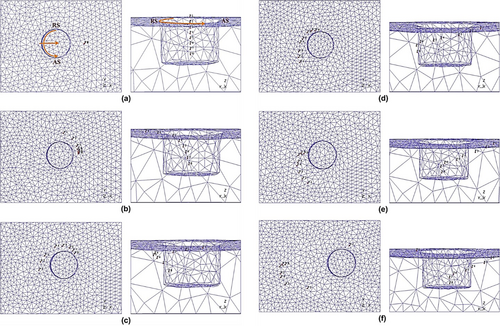
The material flow in the FSP was investigated using Deform-3D software [73]. The material flow at the weld center is illustrated in Figure 12. In Figure 12a, the initial positions of points along the centerline are shown, while Figure 12b–e depict the positions of the same points during the FSW. It can be observed that the points near the bottom of the stir zone (P7 and P8) exhibit a semicircular motion from the leading edge to the trailing edge. Despite the movement of the tool pin, material adjacent to the top surface is drawn toward the advancing side. Notably, the ultimate positions of the points, with the exception of point P1, closely resemble the form of the stir zone, which is an intriguing finding. Point P1 is distinct, as it remains attached to the shoulder and rotates with it for an indeterminate duration.
The CEL method has been developed for modeling severe plastic deformation processes, including machining, rolling, and FSW [74]. In this methodology, the workpiece domain is formulated using the Eulerian approach, while the FSW tool effectively preventing excessive mesh distortion during simulations [75].
The CEL method is instrumental in forecasting material flow and identifying volumetric defects, including tunnel formations, in aluminum during FSW [76]. This approach has also been employed to model underwater FSW employing a stationary shoulder tool [57]. This research explores the mechanisms underlying the formation of defects in USSFSW, emphasizing the effects of nodal forces and material flow velocity. The results of the simulation align well with experimental findings, showcasing three distinct flow paths that emerge during the welding process and ultimately converge in the void area behind the pin, which facilitates an upward movement of the material. It has been noted that when the nodal force falls beneath about 200 N and the flow velocity drops below roughly 0.25 mm/s, the incidence of cavity defects during USSFSW becomes unavoidable.
A subsequent investigation utilizes a CEL method to analyze the effects of the geometric characteristics of a triflute tool on strain, temperature, material mixing, and void formation [56]. The study assesses four distinct tool pin profiles, which include one circular pin and three triflute pins differentiated by their flute radii. The findings indicate that the stir zone is partitioned into SAZ and PAZ, each exhibiting unique material flow patterns (Figure 13). In the SAZ, the movement of material primarily occurs toward the AS, whereas the PAZ directs flow toward the RS. The presence of flutes on the FSW pin tool increases the sweeping rate, strain, and movement of material in the SZ, with smaller radius flutes proving to be more efficient at facilitating material flow and producing defect-free welds when compared to those with larger radii.
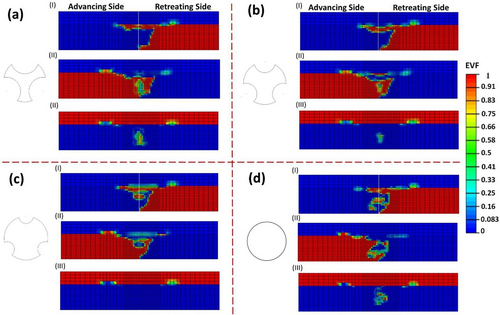
Numerical simulations utilizing a CEL framework have been developed to predict observed defects in the FSW process [77]. This model has shown considerable accuracy in predicting material flow along the workpiece's thickness direction, with stress at the root of the flashes reaching substantial levels ranging from 485.6 to 582.7 MPa. FSW processes between AA5083 and AA7075 have also been modeled using the CEL approach, examining the impact of process parameters such as rotational speed and traverse speed on material flow, strain, and temperature [78]. It was found that increased rotational speed or decreased traverse speed intensified the material flow toward AA5083 in higher sheet surfaces, thus enhancing flow effectiveness.
The CEL method was used to capture the defect shapes and characteristics produced during dissimilar FSW of aluminum alloys [79]. Various tool shapes are utilized to achieve dissimilar welding, and the effects of process parameters—such as traverse speed, rotational speed, and tool tilt angle—are meticulously investigated. Results indicate that increasing traverse speed is critical in inciting defects like voids and tunnels, with a lower tilt angle of 1° leading to long tunnel defects at high rotational speeds.
Moreover, the CEL model has been developed to explore common defects in the FSW process, such as improper substrate joining, tunnel formation, excessive flash, voids, and other surface irregularities [80]. Material flow continuity enables the prediction of both surface and subsurface defects. Additionally, the CEL model successfully predicts defect formation during FSW of AA2024 alloy [81]. Figure 14 illustrates a comparative plot showcasing the defects observed in both simulation and experimental results at various rotational speeds, all conducted at 120 mm/min traverse speed. Effective material flow behaviors exhibit an intercalated zig-zag path, culminating in defect-free welds with 86% efficiency at 1500 rpm and 150 mm/min.
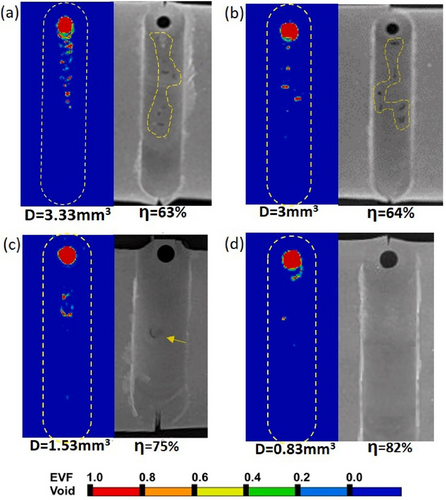
The analysis of the CEL model highlights the sensitivity of the mass scaling factor, suggesting that tailoring this factor can yield a computationally efficient model for defect prediction in the FSW process [82]. The influence of MSF on the CEL method, particularly regarding defect formation, has been addressed, revealing that the predicted surface and subsurface defects and discrete temperature data align closely with experimental observations, with a maximum discrepancy of approximately 0.75 mm for tunnel defects.
Another investigation employing the CEL method focused on the formation processes of hook defects that occur during the FSW of AA6005-T6 aluminum alloy [83]. The emergence of these hook defects has been attributed to the threads on the pin, which promote material flow in the thickness direction, thereby impacting the quality of the weld.
In addition to these studies, the material mixing process has been explored during friction stir lap welding of aluminum and brass using the CEL method [84]. The computational model effectively simulates the SZ formation during the FSLW, predicting both the material mixing and the structural behavior at the Al/CuZn34 interface. Such predictions reveal that aluminum penetrates brass at the center of the stir zone, while brass exhibits an earring shape and penetrates into the aluminum sheet at the periphery, highlighting the complex interactions during the welding process.
Moreover, an approach has been proposed to integrate damage modeling in a three-dimensional FSW model within the CEL framework [85]. This innovative method predicts material flow by addressing issues associated with damage neglect, as well as challenges stemming from traditional damage inclusion methodologies. This advancement paves the way for more precise simulations and enhances the understanding of material behavior during FSW, ultimately contributing to improved welding outcomes.
The modeling of material flow through numerical methods presently remains in its nascent stages, particularly when addressing the complexities inherent in dissimilar welding applications. Significant research is still needed in this domain to enhance the precision and reliability of numerical simulations. One of the major intricacies involved is the prediction of material mixing within the weld zone, which adds layers of complexity to modeling efforts. The challenge is magnified by the fundamental differences in the physical and mechanical properties of the materials being welded, as these differences can affect heat transfer, flow behavior, and ultimately, the quality of the weld. Moreover, the ability to accurately predict potential defects during the welding process through numerical methods is an area where further development is crucial, as existing techniques often fall short in forecasting a comprehensive range of defects.
Another substantial drawback associated with current numerical modeling methods is the considerable length of simulation times that they demand. To achieve accurate models of material flow within the weld zone, it is generally necessary to utilize a very fine mesh size. While this resolution can enhance the reliability of predictions, it simultaneously leads to a significant increase in computational runtime and resource consumption, often rendering practical applications challenging. To tackle this impediment, future advancements might benefit from the continued development of more sophisticated modeling techniques and algorithms designed specifically for the unique challenges of FSW. Additionally, the advent of more powerful computational hardware holds the potential to drastically improve simulation efficiency, thereby enabling the detailed analysis required for more effective modeling of material flow and the prediction of defects in complex welding scenarios.
The challenge of accurately predicting material flow in welding processes hinges significantly on the correct selection of physical and thermal properties of the materials involved. Models that simulate welding must incorporate a comprehensive understanding of these parameters to produce reliable results. Among these, the thermal properties of materials, particularly thermal conductivity, are paramount. This property not only determines how well a material can conduct heat but also influences the thermal profile developed during the welding process. Additionally, the thermal boundary conditions between the material and both the environment and backing plate are crucial. For instance, the convective heat transfer rate describes how heat dissipates from the material surface into the surroundings and directly affects the cooling rate of the weld.
Inaccurate selection of these thermal parameters constitutes one of the significant difficulties in developing numerical models that aim to predict the behavior of material flow. When parameters such as thermal conductivity and convective heat transfer coefficients are miscalibrated, models can produce erroneous temperature predictions. Such misestimations can cascade through the model, leading to incorrect forecasts of material flow behavior during the welding process. For example, if the thermal conductivity is underestimated, the predicted temperature may be higher than it should be. This, in turn, can lead to predictions of increased material flow rates since higher temperatures typically promote greater material mobility.
Moreover, selecting an appropriate material flow model for the base metal adds another layer of complexity to the numerical modeling of welding processes. The dynamic nature of welding makes it vital for flow models to be capable of predicting material behavior across a wide range of temperatures and strain rates. These models must accommodate the rapid changes in conditions that occur throughout the welding process.
3 Material Flow Dynamic During FSW
To effectively investigate material flow during the FSW, it is essential to begin by defining and discussing the various flow regimes involved (Figure 15). Material flow in FSW can be complex, arising from the unique mechanics of the welding process, which includes interactions between the tool and workpieces. Generally, four distinct material flow regimes are observed in FSW, each characterized by unique behaviors and dynamics.
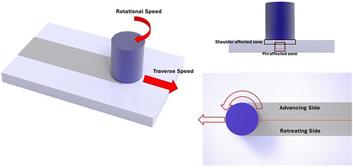
The occurrence of two distinct flow regimes is noted on the advancing and retreating sides of the FSW joint. A combination of the tool's traverse and rotational movements generates an asymmetry in material flow and heat between these sides. As illustrated in Figure 15, the rotational and traverse speeds of the tool are aligned on the advancing side, whereas they are reversed on the retreating side.
Differences in flow around the pin have been investigated, revealing that material on the AS is drawn toward the FSW tool path at the leading edge [86]. In contrast, the material on the RS is deflected away from the tool path and is only extruded by the pin in that region. Further studies have shown that material on the advancing side of the weld enters a zone that rotates and advances simultaneously with the pin, resulting in significant deformation and consequent sloughing off of material behind the pin in arc-shaped patterns [35]. Moreover, the material on the RS of the pin is extruded between the base material and the rotational zone, effectively filling the void left by the material that has sloughed off from the rotational area.
Analysis using PIV has revealed that flow velocities on the advancing side range from approximately 2 to 20 mm/s, while the retreating side exhibits flow velocities between 1 and 5 mm/s [43]. To study these flow patterns involved in the FSW process, finite element models based on solid mechanics have been developed [87, 88]. The flow of material during FSW has been examined through tracer particles, revealing that significant differences exist between the flows on the advancing and retreating sides. After several rotations, sloughing off of material was primarily observed on the advancing side in the wake of the pin.
The debate surrounding whether the material on the advancing side rotates around the pin more than once during welding has garnered significant attention within the literature [89-91]. Several studies indicate that this phenomenon is conditional and can vary depending on specific welding parameters. First, when the material flow is predominantly controlled by the tool's shoulder, it can facilitate enhanced rotation. Second, conducting FSW with high heat input parameters can promote additional rotation by softening the material, allowing increased mobility. Third, when the difference in elevated temperature strength between the material flow zone and the heat-affected zone is minimal, it helps maintain fluidity and flow consistency around the pin [92]. Finally, the type of material being welded is another factor influencing whether the material at the advancing side rotates around the pin multiple times. A study investigating material flow during FSW of steel and aluminum revealed notable differences [93]. In the FSW of aluminum, tracer particles were observed to circulate multiple times around the rotating pin. Conversely, during the FSW of steel, the tracers moved along the rotating pin, passed through the retreating side, and subsequently came to a stop at the rear of the pin.
Beyond the advancing and retreating sides, two additional crucial lateral flow regimes warrant attention: the pin-affected zone and the shoulder-affected zone. The pin-affected zone is directly influenced by the geometry and motion of the tool pin. Moreover, the shoulder-affected zone encompasses the region surrounding the shoulder of the tool. This zone is influenced by the significant contact area between the tool and the workpiece, creating a considerable amount of heat and pressure. The formation of these zones is attributed to different flow mechanisms; the SAZ is characterized by shoulder-driven flow that primarily involves bulk material movement, while the PAZ experiences pin-driven flow that incorporates a combination of layered extrusion flow and bulk material flow.
The flow in SAZ is characterized by the stirring of material along a downward, circular trajectory, influencing the upper one-third of the workpiece thickness. The effectiveness of this stirring action is enhanced when the shoulder surface is designed with features such as scrolls. Conversely, the PAZ flow involves the shearing of material around the pin lateral surface while inducing a downward motion, particularly when a threaded pin is employed. A transition zone is established between the SAZ and PAZ flows, necessitating the convergence and merging of both flows to prevent the occurrence of defects. Such optimal conditions are ensured only when the shoulder exerts appropriate forging action during both advancement and rotation. Furthermore, the welding parameters and the thickness of the plates involved substantially influence the distinct zones within the weld.
The comprehensive investigation of material flow during FSW utilized ER2319 aluminum wire as a tracer material [26]. As depicted in Figure 16, a schematic diagram illustrates the material flow paths at various positions within the stir zone.
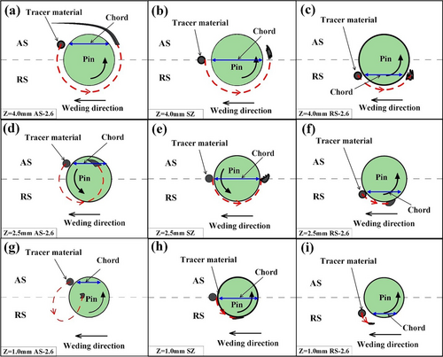
At the top of the SZ, commonly referred to as the shoulder-affected zone, it was found that the material located on the advancing side is deposited in its respective position after undergoing substantial rotation with the pin. Some portions of this material achieved a nearly complete rotation angle close to 360°, indicating an effective mixing and flow process facilitated by the tool's rotation. Similarly, the central material within the SZ experienced a rotation of approximately 214° with the pin, leading to its eventual deposition at the AS. In contrast, the material at the retreating side exhibited a significantly lower rotation angle of 122°. This limited rotation indicates that the material at the RS does not circulate around the pin as effectively; instead, it tends to move slightly backward. Consequently, this results in a static deposition position in the RS that does not change much throughout the welding process.
Moving into the center of the SZ, it became clear that the rotation angle of the tracer material across all positions was lower than that observed at the top of the SZ for the corresponding areas. This difference can be attributed to the driving forces influencing the tracer material. In the center of the SZ, the materials were predominantly driven by the pin's actions alone, whereas at the top of the SZ, both the pin and the tool shoulder played crucial roles in directing the flow of materials, yielding greater rotational influences.
At the bottom of the SZ, the material on the advancing side underwent a rotation of 222° with the pin before being deposited in the center of the SZ. However, this area was marked by inadequate material deposition; the advancing side did not sufficiently fill the region behind the pin. This insufficiency in filling contributed to the formation of root defects within the SZ, highlighting the critical importance of optimal material flow and deposition in achieving defect-free welds. Through this thorough analysis, it is evident that understanding the intricate dynamics of material flow plays a vital role in optimizing FSW processes and preventing common defects associated with insufficient material deposition. Several studies reported the same material flow behavior during FSW [73, 94].
3.1 Tool-Workpiece Interaction
The initial documentation concerning the contact state conditions in FSW can be traced to discussions on the interaction between the tool and the workpiece [95]. Notably, the introduction of sliding between these components was emphasized, highlighting the relative motion that occurs during the process. Simultaneously, the concept of sticking was introduced, describing a condition in which the material rotates cohesively with the tool at the same velocity [96]. This early exploration laid the groundwork for understanding contact states within FSW.
A significant advancement in the analysis of contact states was achieved through a comparative study of tool rotational speed and the speed of a material tracer [97]. Utilizing high-frequency consecutive x-ray imaging during the welding process, researchers evaluated the material velocity around the tool. This investigation revealed a mixed sticking/sliding condition around the pin. The ratio of material flow rate to tool rotation rate was found to range from 0.4 to 0.8, initially increasing from 400 to 600 rpm before decreasing again between 600 and 1000 rpm. This research experimentally validated the presence of mixed sticking/sliding conditions and demonstrated that welding parameters significantly impact the contact state.
Further investigations into the sticking/sliding phenomenon were conducted through FSW trials, where an intentionally enhanced oxide layer was introduced between aluminum plates [37]. Post-mortem analysis tracked the displacement of this oxide layer, allowing researchers to estimate that the velocity of the material flow was lower than the pin peripheral velocity. This finding further confirmed the existence of a mixed contact state rather than a condition of full sticking.
The PIV technique was employed to analyze the material flow and measure the strain rate around the tool pin during FSW [98]. Micro-spherical glass tracers, which were incorporated into a transparent viscoplastic material with similar densities, served as the experimental medium. The results indicated that the maximum velocity observed was 60% of the pin peripheral velocity, occurring near the pin surface. This finding confirms the presence of a mixed sticking and sliding contact at the tool-pin interface.
A method to investigate the sticking/sliding contact state between the tool and the workpiece involved monitoring the torque during FSW operations [99]. Observations revealed fluctuations in torque varying according to the welding conditions. These fluctuations were correlated with different interfacial interactions, resulting in variations in amplitude. The research estimated the fraction of sliding to range from 0.43 to 0.83, depending on various welding parameters within a range of 75 to 375 mm/min and 475 to 1180 rpm.
In conclusion, the exploration of contact state conditions in FSW has significantly advanced our understanding of the interactions between the tool and the workpiece, particularly through the concepts of sticking and sliding. Early investigations laid a foundational framework, while subsequent studies employing high-frequency x-ray imaging and torque monitoring have provided empirical evidence of mixed sticking/sliding conditions.
3.2 Filling Cavity Process
Since the early investigations into FSW, a debate has persisted regarding whether the process involves material stirring and extrusion or a combination of both mechanisms. The stirring state is characterized by chaotic material mixing as it is transported behind the tool [100], whereas the extrusion state describes a cyclical, continuous, and repetitive shearing of a layer that is subsequently expelled through a mobile die formed by the tool, backing plate, and base material [101]. Alternatively, the FSW may be considered a hybrid of these two mechanisms.
Determining the mechanism responsible for the cavity filling during the welding process has been a significant concern since the technique's inception. Early assertions suggest that both extrusion and stirring mechanisms coexist, even if not all material undergoes stirring [95]. Observations show that the stirred material comes from the upper part of the plate, while the rest of the material is extruded around the retreating side of the pin.
Analyses have concluded that actual stirring predominantly takes place in the weld upper section because of the shoulder action, while flow around the pin is primarily characterized by extrusion [102]. It has been suggested that the simultaneous stirring in the upper section and extrusion in the central-lower section create vertical motion along the longitudinal axis of the weld.
Assumptions regarding the stirring and extrusion debate have been explored, with findings indicating that markers rotate multiple times with the tool, attributed to the stirring induced by thin rotational flow around the pin during FSW [103]. Moreover, observations from various experiments reveal that particles consistently make multiple rotations around the pin when sound welds are formed, leading to the conclusion that stirring occurs within a thin rotational flow symmetrically formed around the pin in successful FSWs [91].
Some researchers argue that the material surrounding the pin does not genuinely undergo stirring, as mixing between adjacent layers is not observed [39]. Instead, the material engages at the tool's leading side within a rotational zone around the pin, flowing like the extrusion process. As it circulates around the pin, the material experiences plastic deformation without significant mixing, suggesting that adjacent layers maintain their relative positions during this deformation.
Various experimental methodologies have been employed to discern whether extrusion, stirring, or a combination of both occurs behind the pin during FSW. Despite the insights gained from numerous contributions within the FSW community, a definitive resolution to the core question remains elusive. The literature reveals inconsistencies, as similar welding configurations have led to differing conclusions regarding the presence of stirring or extrusion. A comprehensive perspective suggests that the phenomena occurring around and behind the pin are influenced by factors such as plate thickness, pin profile, base material, and welding parameters [39]. Consequently, it is likely that both mechanisms coexist within the mid-thickness of an FSW plate, with stirring prevailing in the upper region due to the action of the shoulder and extrusion dominating at the bottom as a result of the pin's influence.
3.3 Onion Ring
In the analysis of material flow during FSW, the presence of onion rings is regarded as an inevitable phenomenon. These features are predominantly observed in the pin-affected zone during cross-sectional evaluations and are named for their distinctive circular-oval morphology. The formation of these rings commences at the center and radiates outward toward the periphery of the pin-affected zone, with spacing between the rings decreasing in the outer regions [104-106].
The mechanisms underlying the development of onion rings have been linked to the cyclic deposition of sheared metal layers throughout the welding procedure, with one layer being deposited for each rotation of the tool [104]. This cyclic process leads to a stack of semicylinders aligned along the welding direction. It is posited that during the period required to fill the cavity created by the welding tool, air occupies this space, resulting in the oxidation of the freshly sheared metal. Consequently, when cross-sections are made perpendicular to the welding line, these layers appear as onion rings, characterized by wider spacing at the center and narrower spacing at the edges due to geometric influences (Figure 17). The theoretical framework explaining onion ring formation was initially validated through the analysis of multiple sections from friction stir weld samples, which revealed significant evidence of stacked layers. Additionally, simulations using plasticine models demonstrated the resultant sections and the presence of “rings,” thereby reinforcing the theoretical assertions (Figure 17).
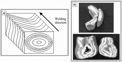
Microstructural investigations have indicated notable variations in grain size within the stir zone, where alternating bands of onion rings exhibit fine grains measuring 5–10 μm and very fine grains ranging from 3 to 5 μm [107]. This observation implies that variations in grain size may reflect the origins of the stir zone's characteristics.
Further studies have clarified that the space between the alternating bands corresponds to the distance traversed by the tool during a complete rotation [108]. The resulting banded microstructure displays a segregation pattern featuring alternating regions that are enriched in hard particles and those that are deficient in such particles.
Importantly, it has been determined that onion rings do not adversely impact the mechanical strength of the joint, regardless of whether the materials are similar or dissimilar aluminum alloys [109]. Thus, despite ongoing discussions regarding the origins and implications of onion rings, they do not constitute a significant concern within the context of FSW processes.
3.4 Defect Formation
The flow of material within the SZ is a critical characteristic that reflects the development of various welding defects. The movement of material around the tool and beyond the boundaries of the workpiece acts as a key predictive indicator for assessing the potential formation of defects. For instance, defects such as flash, tunnels, voids, and cavities primarily stem from inadequate material flow and insufficient deposition behind the tool [110].
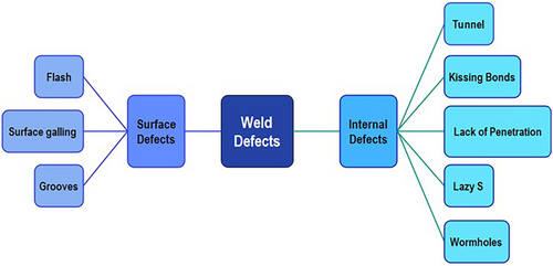
Prominent surface defects include surface galling, flash, and grooves, while internal defects frequently consist of tunnel defects, kissing bonds, lack of penetration, lazy S defects, and wormholes (Figure 18). Understanding these flow dynamics is essential for improving weld quality and minimizing defects during the FSW process.
Surface galling manifests as blister-like defects arising from the loss of highly plasticized material, which adheres to the tool surface during the welding process (Figure 19a) [111, 118]. This phenomenon is particularly problematic in high-speed applications where the material's viscosity and flow characteristics may lead to the material sticking to the tool rather than being properly incorporated into the weld joint. Similarly, flash defects occur when excessive heat causes the plasticized material to flow outward from the shoulder of the tool, accumulating on the retreating side of the weld (Figure 19b) [18, 119]. This can compromise the overall appearance of the weld and can also suggest a disruption in the balance of the tool's contact pressure, leading to unintended material expulsion.
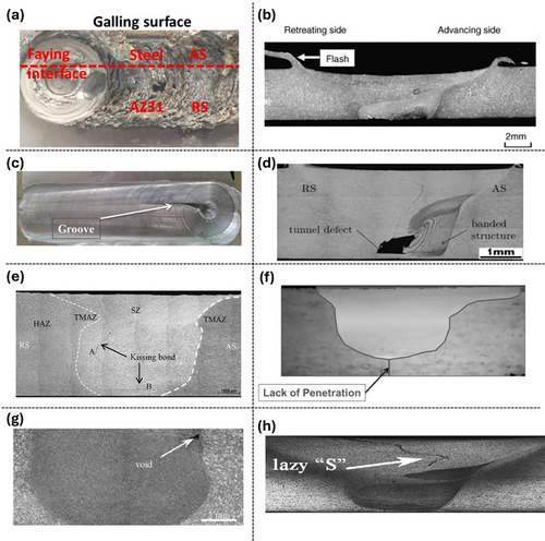
Grooves are defined as elongated voids aligned in the traverse direction of the weld, indicating that the plasticized material has not sufficiently filled the cavity left by the tool (Figure 19c). The occurrence of this defect is predominantly associated with low rotation speeds and high traverse speeds [120]. Typically, grooves are observed primarily on the advancing side of the weld [121]. A lack of deposited plasticized material from the retreating side to the advancing side arises when low heat input per unit length is applied.
The restricted flow of material, hindered by the rotating tool, results in a channel-like zone devoid of material on the advancing side. Enhancing the rotational speed while reducing the traverse speed has been shown to improve material flowability, potentially eliminating the formation of groove defects [122]. Additionally, the application of a tool tilt angle assists in compressing the material situated behind the traversing tool. Tool tilting further improves material flow, thereby increasing the likelihood of achieving a defect-free and high-quality weld.
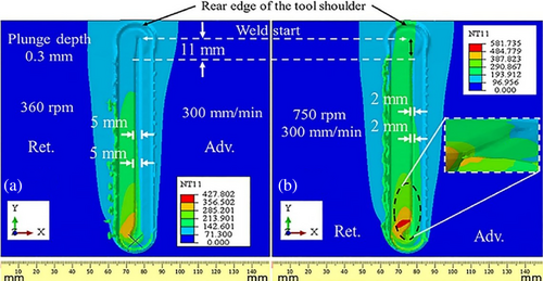
In Figure 20, visual representations highlighting completely and partially failed joints illustrate the consequences of improper processing parameters that result in insufficient plasticized material, adversely affecting weld quality [123]. Increasing the tool rotation speed, thereby elevating heat input, has been correlated with enhanced weld quality. For instance, FSW conducted at a rotation speed of 360 rpm and a traverse speed of 300 mm/min yields an incomplete joint across the full length of the workpiece. However, raising the rotational speed to 750 rpm significantly improves weld quality, while the width of the surface groove diminishes by more than twofold when comparing the speeds of 360 rpm.
Tunnel defects in FSW are often attributed to insufficient heat near the AS, a condition that typically arises from high traverse speeds or low rotational speeds. This inadequacy leads to poor material flow and the subsequent formation of cavities (Figure 19d) [124]. Tunnel defects occur specifically when the material flow from the RS to the AS is insufficient due to the rotation of the tool [125]. To achieve a defect-free weld, it is crucial to maintain a material periodic flow from a defined region surrounding the pin and beneath the shoulder [126]. Moreover, excessive rotational speeds of the tool, combined with high welding speeds, can result in abnormal stirring of the materials, primarily due to a steep temperature gradient along the thickness. This abnormal stirring can create flow separation, ultimately leading to voids on the advancing side [125].
To investigate tunnel and cavity-type defects, a CFD model was developed based on the Sheppard-Wright material model and Coulomb's friction law [127]. The analysis revealed that inadequate material flow is the primary cause of cavity evolution, which can extend into tunnel formations, with susceptibility increasing at higher traverse speeds. Research indicates that the region near the tool pin tip is the most likely site for tunnel defect formation, attributed to relatively colder material and sluggish flow characteristics in that area [128]. The probability of tunnel defects can be reduced by ensuring adequate rates of heat generation and dispersal on both sides of the joint, as well as appropriate material deposition behind the traversing tool. Different kinds of defects, such as tunnel and void defects related to FSW, were predicted using the CEL method [129]. A zero tilt angle led to the formation of tunnel defects, while a tilt angle of one degree resulted in voids and cavities. Conversely, using a two-degree tilt angle resulted in a weld that was free of defects. However, parameters involving a three-degree tilt angle produced defective welds.
Kissing bonds are a type of internal defect characterized by inadequate heating, which prevents effective metallurgical bonding between the base materials. In this case, only mechanical interlocking occurs at the surfaces, significantly compromising the joint's strength (Figure 19e) [130]. Another defect, known as lack of penetration, arises when the tool pin is too short to adequately reach the required material thickness for forming a solid weld (Figure 19f) [131]. The root defect originates from insufficient plastic material flow beneath the tool pin, often exacerbated by improper tool geometry. Additionally, when the tool pin's diameter is equal to or less than half the plate thickness, it can initiate the formation of a lack of penetration. Low welding pressure also contributes to the occurrence of LoP [132].
Voids, or wormhole defects, are indicative of high welding speeds combined with low axial pressure, leading to the formation of voids within the welded material without a distinct preferential orientation (Figure 19g) [133, 134]. These internal voids can significantly diminish the mechanical performance of the joint and highlight the complexities associated with FSW. The generation of voids can be forecasted by analyzing the material flow patterns derived from a CFD model [135]. The model indicates that as the traverse speed rises from 100 mm/min to 250 mm/min, there is a corresponding decline in material flow and a heightened likelihood of void formation.
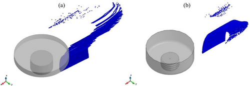
Lazy S defects occur when aluminum reacts with oxygen at elevated temperatures, forming a brittle aluminum oxide layer at the welded edges, which hinders effective bonding (Figure 19h). Adjusting the heat input by modulating process parameters can help eliminate the continuous or zig-zag pattern of the oxide layer by dispersing the oxide particles throughout the weld zone. Furthermore, proper surface preparation prior to welding can reduce the likelihood of Lazy S defect formation. The joint line remnant defects, including Lazy S defects, were predicted by employing the ALE approach through the numerical tracer particle method [136]. In this analysis, a total of 30,000 material tracer particles were uniformly distributed over a plane to represent the oxide layers. The placement of the oxide layer during the welding process is used for predicting the joint line remnant defect, as illustrated in Figure 21.
3.5 Influencing Parameters
3.5.1 Rotational and Traverse Speed
The interplay between rotational and traverse speeds is crucial in determining the material flow dynamics during FSW, directly impacting the quality and mechanical properties of the resultant weld [137]. The rotational speed generates the necessary heat through friction, facilitating the softening of the material; however, this effect is significantly influenced by the traverse speed, which dictates the rate at which the tool moves along the joint. An optimal combination of these parameters ensures adequate heat generation and material flow, promoting effective mixing and minimizing defects such as voids. If the traverse speed is too high relative to the rotational speed, insufficient heat may be generated, resulting in inadequate material softening and poor weld quality. Conversely, excessively low traverse speeds can lead to overheating and grain coarsening, adversely affecting the microstructure.
FSW tests were performed on 4 mm thick magnesium alloy plates, keeping the traverse speed constant while varying the rotational speed from 300 to 3000 rpm [138]. Changes in the stir zone, including the shape and extension of the PAZ, SAZ, and their transitions, were examined, highlighting the relationship between the process parameters and the resulting material flow.
The impact of rotational speed and traverse speed on material flow behavior was investigated using a tracer material inserted within the weld [27]. Macrographs of the joint cross-sections, with the tracer positioned at the weld centerline, are presented in Figure 22. The tracer material is observed to be deposited in the stir zone, with a noticeable offset toward the AS of the weld. Minimal vertical material flow through the SZ is evident in the metallographic sections. Although the tracer material height remained constant, its width expanded by nearly 600%, indicating some degree of mixing with the base material.
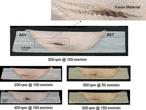
At the lowest traverse speed of 50 mm/min, a broader vertical distribution of the tracer material was observed compared to moderate traverse speed conditions, suggesting a greater extent of mixing at slower travel speeds. In contrast, the highest rotational speed of 400 RPM resulted in the least spreading of tracer material across the weld width, although it exhibited the most significant vertical dispersion. While higher rotational speeds were anticipated to enhance mixing, it appears that the elevated temperatures associated with these speeds may reduce flow stress and the coefficient of friction between the tool and the weld zone material, ultimately leading to a decrease in gross mixing.
Another study investigated how rotational speed influences material flow characteristics while keeping the traverse speed constant at 400 mm per minute [97]. A range of rotational speeds, from 200 to 1000 rpm, was used in the research. The results indicated that the material flow regions created between 600 and 1000 rpm exhibited nearly uniform characteristics, forming a concentric structure. Furthermore, it was noted that the tracer ceased to rotate around the pin at 300 rpm.
One of the most significant challenges associated with FSW of dissimilar metals lies in the formation of intermetallic compounds. These IMCs are characterized by their brittle nature, which can substantially compromise the overall strength and integrity of the resulting weld joints [139]. The formation of these compounds is a predictable consequence of the welding process, largely attributable to their low enthalpy of formation. Despite their inherent brittleness, the emergence of IMCs signals successful metallurgical bonding between dissimilar metals, thereby indicating that the welding process has achieved some degree of structural integrity.
However, this dual nature of IMCs poses a dilemma. On one hand, their formation is essential for bonding; on the other, the characteristics of these intermetallics must be managed effectively to ensure that they do not detrimentally impact joint performance. Optimal management of factors influencing IMC formation is thus critical for achieving strong and durable joints. Research has demonstrated that operating at low traverse speeds during the welding process can lead to the development of excessively thick IMCs. These thick IMCs have been shown to result in significantly poorer tensile strength in the welded joints [140].
Furthermore, additional studies highlight that increasing the rotational speed or decreasing the traverse speed not only expedites the growth kinetics of the IMC layer at the joint interface but also affects its formation and morphology due to enhanced peak temperatures during the welding process [3]. Consequently, when welding dissimilar metals, it is crucial to choose process parameters that not only minimize potential defects but also consider other factors, such as the formation of intermetallic compounds, to ensure the creation of an effective joint.
3.5.2 Tool Design
The design and dimensions of the FSW tool are pivotal in influencing material flow during the welding process, as they directly affect heat generation, material mixing, and the overall integrity of the weld. Key design features, including the tool's shoulder diameter, pin geometry, and length, determine the contact area and the distribution of forces on the workpieces [141], which in turn influence the frictional heat produced and the flow characteristics of the softened material. A well-designed tool facilitates optimal heat transfer and ensures effective stirring of the material, promoting proper flow and minimizing the risk of defects such as voids or insufficient bonding. Additionally, variations in tool geometry lead to different flow patterns, impacting the microstructural evolution of the weld zone.
In FSW, the tool consists of two primary components: the shoulder and the pin, each playing a vital role in the welding process. The shoulder, which is the larger flat section of the tool, generates significant frictional heat as it rotates against the workpieces, softening the material and providing a supportive backing that helps contain the softened material around the pin. This design facilitates effective heat distribution and material flow control. The pin, protruding from the shoulder, penetrates into the workpieces and creates a stirring action that promotes the mixing of the softened material, enhancing interfacial bonding and ensuring a homogeneous weld.
A difference between the actions of the shoulder and the pin on the material has been noted [102]. It has been determined that actual stirring takes place only in the upper section of the weld plates due to the shoulder's action, while the pin is solely responsible for extruding the processed material. A CFD model has been created to examine how the features of rotational versus non-rotational shoulders and pins affect the behavior of material flow in FSW [142]. The study evaluates four different tool designs that incorporate both rotational and non-rotational shoulders, as well as pins with or without triple facets. The findings indicate that the use of a rotational shoulder significantly enhances material flow and increases flow velocity, while a non-rotational shoulder tends to decrease both aspects. Additionally, multiple facets on the pin improve the material flow during non-rotational shoulder FSW.
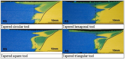
The impact of pin shape and size on material flow has been a subject of research by various scholars in the field. A study adopted a plasticine of primary colors to examine and quantify the mixing process [143]. The effect of various tool pin profiles, which included circular, square, triangular, and hexagonal shapes, was investigated within this context. Macro-graphs of plasticine joints, recorded for various tool pin shapes, are presented in Figure 23. The macro-graphs show that mixing induced by the pin is superior when square and triangular pin profiles are utilized. The superior performance of these pins may be partly attributed to their dynamic volume to static volume ratio.
The material flow characteristics of two unthreaded pins—the circular pin and the tapered circular pin with three flats (TC3F)—were analyzed, revealing that the TC3F pin alters the material flow and creates variations in material flow velocity compared to the circular pin [19]. Furthermore, the material flow of three distinct pin types, including the column pin, taper pin, and taper threaded pin, was studied using a marker insert technique [144]. A three-dimensional flow visualization demonstrated that the vertical material flow was more pronounced when the taper-threaded pin was employed. In addition, investigations into the plastic flow associated with various tool shapes during friction stir spot welding were conducted using a particle method [145]. It was suggested that a tool featuring a triangular pin improved material flow, resulting in spot welds of enhanced strength.
The effect of pin profile on material flow was studied through experiments using plasticine with various pins such as circular, square, hexagonal, and triangular tapered tools [143]. The results indicated that the material was transported in lumps around the pin for pins with faces, leading to a higher sheared material volume and thus favoring improved material flow. Furthermore, investigations show that increased pin diameter improved stirring intensity but decreased the ability to close voids [146].
Further investigations on the material flow during FSW and the impact of pin features were conducted using both unthreaded and threaded tools. Modifications in material flow were assessed through the use of tracer markers embedded in the weld path. It was found that the thread generated increased vertical motion as a result of the wash and backwash of the thread [144].
Research has been conducted to evaluate the influence of pin tool thread orientations on material flow during FSW [147]. The left-hand thread pin tool, when rotated clockwise, produced satisfactory welds without any visible defects. However, when the right-hand thread (RHT) pin was employed in the same clockwise direction, some cavities or bonding defects were seen near the lower surface of the FSWed joint. To enhance comprehension of the material flow, the effects of pin thread orientation, and the resultant defects, a schematic illustration is provided in Figure 24.
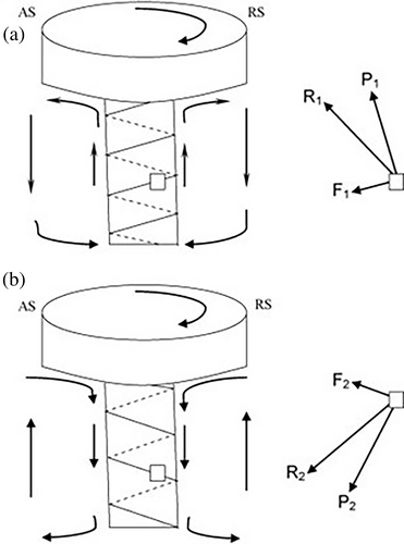
During the FSW process, the plasticized material surrounding the pin experienced two distinct forces. The first, denoted as pressure P1, acted perpendicularly to the thread surface because of the pin rotation. The second force, referred to as traction force F1, ran parallel to the thread surface as a result of the friction between the thread and the plasticized material. The relationship of these forces exerted on the plasticized material is depicted schematically in Figure 24a.
In the case of the RHT tool, the interplay between these two forces (P1 and F1) caused the plasticized material to flow upward from the bottom of the RS in the direction of R1, ultimately depositing at the trailing side of the pin tool. It is important to note that the flow of material was not vertical but rather inclined upward from the RS to the AS at the trailing side, a consequence of the clockwise rotation. The continuous rotation of the weld tool led to an increased volume of plasticized material, which migrated from the bottom of the thread to the shoulder of the rotating tool. Given that FSW is characterized as a constant volume process, the flow path being restricted by the shoulder, the pin, the back plate, and the undeformed base material resulted in the transported material beneath the shoulder being directed downward to fill any existing cavities at the bottom of the joint, which had formed due to the inclined upward flow of material near the thread.
Conversely, with the LHT pin tool rotating in a clockwise manner, the plasticized material around the thread was subjected to pressure P2 and traction force F2, as illustrated in Figure 24b. The interaction of these two forces (P2 and F2) compelled the plasticized material near the thread to move downward and simultaneously from the RS to the AS in the direction of R2, thereby depositing it at the trailing side of the weld tool. Again, due to the constant volume nature of the process, the material that was transported to the lower region was forced to ascend after filling the potential cavity located near the bottom of the pin. Consequently, with the LHT pin tool, the downward-moving plasticized material maintained direct contact with the threaded pin surface, which facilitated a more effective joining at the base of the welded joint.
A CFD model has been developed to evaluate the impact of tool thread pitch on material flow during the FSW [148]. The study examines four tool designs, each featuring a different thread pitch ranging from 1.0 to 3.0 mm. Information regarding the material flow velocity within the shear layer is obtained by analyzing the distribution of tracking particles released from the starting points of streamlines, allowing for an exploration of how thread pitch influences the material flow velocity. Observations indicate that the movement of tracking particles in the vertical direction is minimal when using an unthreaded pin, as illustrated in Figure 25. Furthermore, as the thread pitch increases from 1.0 to 3.0 mm, the upward displacement of tracking particles diminishes, and the degree of dispersion among the tracking particles becomes less pronounced.
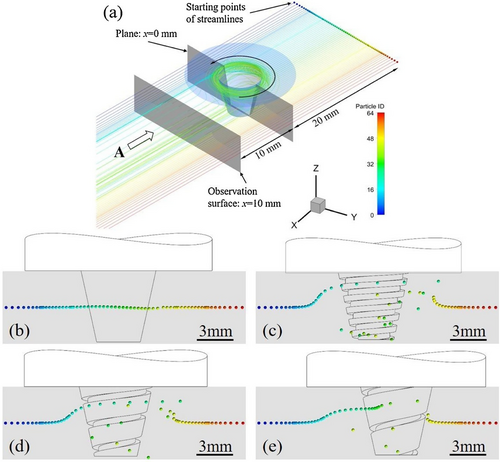
In another study, the impact of pin thread depths on material flow was examined. The findings indicated that as the thread depth of the pin rose from 0 to 0.75 mm, the material flow was enhanced more effectively [149]. This improvement led to a greater swept area around the tool pin and caused the width of the SZ to increase from 5.78 to 8.64 mm.
A recent study utilized a CFD model to investigate the thermo-physical phenomena in FSW involving two distinct tool geometries: a conical tool and a triflat tool [150]. The findings reveal that the deformation zone generated by the triflat tool is significantly larger than that produced by the conical tool. Figure 26 presents a snapshot of the material flow initiated by both the conical and triflat tools at horizontal planes located 1, 3, and 5 mm below the top surface. The material flow velocity associated with the triflat tool is markedly greater than that of the conical tool. Specifically, the maximum material velocity achieved by the triflat tool at the edge of the flat area measures 0.165, 0.144, and 0.123 m/s at the three analyzed planes, whereas the maximum material velocities for the conical tool at the same positions are notably lower at 0.051, 0.044, and 0.038 m/s.
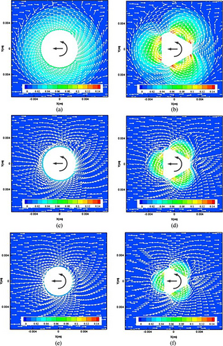
This disparity in material flow velocity is attributed to the differences in tool design. In the case of the axisymmetric conical tool, the tool velocity consistently aligns parallel to the tangential direction of the interface. In contrast, the asymmetrical triflat tool exhibits a non-zero included angle (h) between the tool's velocity and the interface at the pin side flat area. Consequently, the material flow velocity in this region is amplified compared to other areas.
The influence of pin size and taper angle on the thermal processes and plastic material flow was examined using a CFD model [151]. The findings indicate that both the pin size and taper angle significantly impact the behavior of plastic material flow, specifically by expanding the shear zone and enhancing the material flow region and velocity. As the pin diameter increases, the viscosity of the material adjacent to the pin decreases while both the temperature and flow velocity increase. Consequently, a larger pin diameter facilitates greater rotation of the surrounding plastic material around the tool.
The effects of pin threads and flats on material flow behavior were analyzed during the processes of dissimilar FSW of aluminum and copper using CFD [152]. To assess the different mechanisms of influence that threads and flats exert, three distinct models featuring different pin characteristics were developed: a conical pin, a threaded pin, and a threaded-flats pin. The results indicated that the threads predominantly enhance the longitudinal movement of the materials, occurring in a direction perpendicular to the horizontal plane. Conversely, the flats significantly enlarge the range of plastic flow and the mixing zone of the materials on the horizontal plane. Furthermore, it was found that the area of material mixing is noticeably greater behind the threaded-flats pin compared to both the threaded pin and the conical pin. This observation confirms that the combined effect of “threads + flats” leads to a more vigorous mixing of the two-phase materials, as depicted in Figure 27.
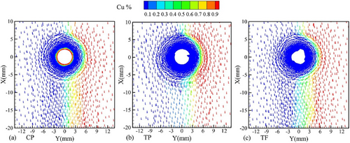
The material flow dynamics during FSW utilizing a protruding cylinder tool were examined [153]. The experimental setup employed two distinct types of tools: the conventional tool (C-tool) and the modified tool (T-tool) (Figure 28). Both tools are designed with a smooth cylindrical pin. However, the modified T-tool incorporates an additional protruding cylindrical feature on the pin, measuring 1 mm in diameter and 0.5 mm in length. Figure 28 illustrates diagrams of material flow for the different tool configurations. The T-tool demonstrates that the extrusion effect created by the protruding cylinder promotes outward material movement, enhancing the stirring action of the pin. This results in a more uniform material flow compared to the C-tool. The findings reveal that the inclusion of the protruding cylinder in the modified tool leads to a notable improvement in the surface quality of the weld, an increase in the width and area of the stir zone, and a refinement of the grain structure.
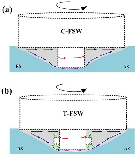
The configuration of the tool shoulder, in conjunction with the shape of the pin, significantly affects the flow of material during the FSW process. Notably, the implementation of a scrolled shoulder has been demonstrated to enhance stirring abilities [154]. Parallel observations have been recorded regarding other features, such as concentric circles, knurlings, ridges, and scrolled shoulders, in the context of FSW applications [155]. When maintaining a consistent shoulder diameter, the incorporation of more sophisticated shoulder designs leads to increased temperatures attributed to a larger interface surface area. This augmentation in temperature facilitates better stirring, as it reduces the viscosity of the material being stirred and amplifies the mechanical action applied to the plasticized substance.
Additionally, the profile of the shoulder's end—whether it is flat, convex, or concave—also influences material flow dynamics. Research suggests that a flat-end configuration is less efficient in retaining the flowing material beneath the shoulder when compared with a concave shoulder that is inclined at a slight angle (6°–10°) relative to the flat surface [156]. The concave profile acts as a reservoir for the material displaced by the pin, effectively minimizing the formation of a flash. When utilizing a concave end surface, it is advisable to tilt the tool by 1°–3° from the perpendicular to the workpiece in the opposite direction of travel, which aids in promoting effective material flow beneath the shoulder's end.
Conversely, convex shoulders are rarely applied, as their design tends to redirect material away from the center of the tool [118]. However, there have been notable cases where robust welds were produced using convex shoulders in the FSW of stainless steel. This represents one of the limited studies that support the use of convex shoulders in friction stir butt welding [157].
Tool wear is an inevitable phenomenon in the FSW process that can significantly influence tool performance, particularly affecting the tool pin geometry in two primary ways. First, in the case of threaded tools, extended usage leads to notable wear on the tool threads [19, 158]. As the threaded tool ages, the wear can alter the material flow characteristics, transitioning from the vertical material flow primarily associated with new threaded tools to the flow pattern observed when using circular tools. The distinct difference arises because threaded tools are designed to optimize vertical flow, facilitating the effective stirring of the material. Once the threads are compromised, the vertical flow diminishes, affecting the mixing and intermetallic bonding of the metals being welded.
Second, in circular tools, the nature of tool wear manifests predominantly as a decrease in the pin diameter over time. The implications of this dimensional change are profound, as a smaller pin diameter directly leads to a reduction in the size of the SZ. Furthermore, this change can disrupt the optimal ratio of the shoulder diameter to the pin diameter, which is critical for maintaining the necessary pressure and heat generation required to achieve effective welding. Deviations from the ideal ratio can lead to defects such as voids within the SZ.
3.5.3 Preheating
Preheating plays a significant role in enhancing material flow during FSW by reducing the viscosity of the workpieces and facilitating easier deformation of the material. By elevating the temperature before the welding process, preheating helps to minimize the thermal gradient between the tool and the workpieces, which can lead to more uniform heat distribution during the operation. This uniformity is crucial for achieving optimal material flow, as it prevents localized overheating or underheating that could result in defects such as voids or incomplete bonding.
An investigation was conducted to assess the impact of preheating treatment on the material flow of joints made from aluminum alloy and steel through FSW [159]. A CFD model of butt FSW was developed using FLUENT software. To analyze the flow characteristics of the two different materials during the FSW process, the flow trajectories of steel and aluminum alloy were simultaneously observed in a stable welding state, as illustrated in Figure 29. Distinct colors were employed to differentiate between the various particles, with the color bar indicating the particle identification (ID). Under conditions without preheating treatment, the plastic flow properties of steel were observed to be poor, leading to only minimal material flow during FSW (Figure 29a). In contrast, when preheating treatment was applied, there was a notable increase in material flow within the FSW process (Figure 29b). Despite this improvement in steel, preheating treatment had a minimal effect on the plastic flow velocity of the aluminum alloy (Figure 29). Overall, the preheating treatment enhanced the flow velocities of the plastic materials and mitigated the differences in flow velocities between the two materials.
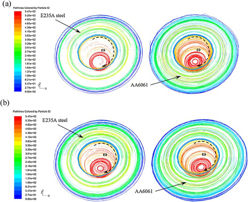
3.5.4 Tilt Angle
The tool tilt angle in FSW is a significant determinant of joint quality. This angle is defined by the positional relationship between the workpiece and the FSW tool. A zero angle indicates that the FSW tool is perpendicular to the weld plate, while a non-zero angle signifies that the tool is tilted relative to the plate [160-162]. Early experiments have demonstrated a strong correlation between the integrity of welds and the tool tilt angle [116]. Specifically, when using a smaller tilt angle, the material flow behind the pin is often insufficient, resulting in void defects. Conversely, at larger tilt angles, void defects can also arise, primarily due to weld flash generated at the RS, where there is inadequate material to fill the cavity in the stirring zone.
In a recent study, a CFD model was utilized to explore the effects of tool tilt angle on material flow during FSW [163]. The findings reveal that utilizing a tilted welding tool significantly increases the frictional force at the interface between the tool and the workpiece, which markedly enhances the velocity of material flow behind the tool. Additionally, the inclined orientation of the tool facilitates a more efficient stirring action on the surrounding material, fostering better mixing and ultimately leading to the improved quality of friction stir welds.
Figure 30 illustrates the top view of the predicted material flow paths for tool tilt angles of 2.5° and 0°, respectively. Observations indicate that the material ahead of the welding tool travels a specific distance before being deposited into the weld, during which temperature, strain rate, and velocity vary along the flow path. The differences in material flow paths for varying tilt angles are striking. In the case of the tilted welding tool, material motion exhibits a more complex pattern as it flows through and is subsequently deposited by the tool. In contrast, when the tool is positioned at a 0° tilt angle, the material moves in a simpler mode with less noticeable horizontal flow. Furthermore, the material located ahead of the tilted tool typically travels a longer distance before deposition into the weld compared to the scenario with a 0° tilt angle.
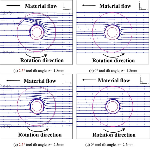
CFD models were developed to investigate material flow behavior in FSW, analyzing the effects of the tool tilt angle [164]. A significant distinction was noted between scenarios with a tool tilt angle of 0° and one of 2.5°. At a 0° tilt angle, the streamlines were observed to be regular, indicating a consistent flow of material. Conversely, when the tilt angle increased to 2.5°, the streamlines at the retreating side became denser, illustrating a clear expansion of the material flow region. This change is attributed to the tool being tilted toward the trailing side, which enhances the forging effect exerted on the material in that area. As the material navigates around the tool, the material on the retreating side is significantly influenced by the shoulder, resulting in an upward flow.
Further analysis revealed that at the 0° tilt angle, streamlines traversing the tool remained predominantly horizontal. In contrast, at 2.5°, the streamlines exhibited a tendency to disperse vertically, tilting toward the leading side as the material flowed across the tool.
To provide a clear demonstration of the material flow intensity, tracer particles were strategically positioned along a transverse line. As depicted in Figure 31, the distribution patterns of both horizontally and vertically oriented tracer particles showed minimal changes at a 0° tilt angle. However, at a 2.5° tilt angle, the horizontally set tracer particles displayed a noticeable upward movement, while the vertically set tracer particles became more dispersed. This observation indicates that a 2.5° tool tilt angle significantly enhances the migration of tracer particles in both vertical and horizontal directions, reflecting an intensified and more dynamic material flow during the FSW process.

4 Material Flow in Bobbin FSW
Bobbin tool FSW is recognized as a variant of FSW that is rapidly evolving into a reliable joining method (Figure 32). This technique is designed to effectively generate welds throughout the entire thickness of the sheet material, utilizing a unique tool design that consists of two shoulders—one located on the upper side and one on the lower side—alongside a penetrating pin [166].
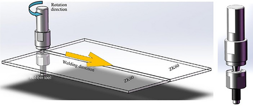
The incorporation of an additional shoulder at the bottom, which replaces the traditional fixed backing plate, facilitates a self-supporting structure. This modification significantly reduces root defects commonly associated with FSW joints and enhances the thermo-mechanical cycle during the welding process [167]. Furthermore, improved characteristics in the microstructure of welded joints are demonstrated through the BTFSW process. A more uniform microstructure distribution throughout the material thickness is achieved, attributed to lower temperature and strain gradients in comparison to conventional FSW methods [168]. This enhancement highlights the increasing preference for BTFSW in various industrial applications where joint quality is crucial.
Contrary to conventional FSW, BTFSW exhibits complex material flow due to the presence of dual rotational shoulders positioned on either side of the weld centerline [169]. An analog plasticine model has been employed to investigate the material flow behavior of BTFSWed AA6082-T6 alloy. Within BTFSW, the SZ is subdivided into an upper SAZ, a lower SAZ, and a PAZ [170]. The upper and lower shoulders direct the material flow from the AS to the RS along the pin toward the center of the SZ. The plasticized material accumulating at the center is compacted to swirl toward both surfaces of the joint (Figure 33). Additionally, the tool tilt angle in BTFSW is maintained at zero with no adjustments, resulting in less turbulent vertical material flow during the welding process.
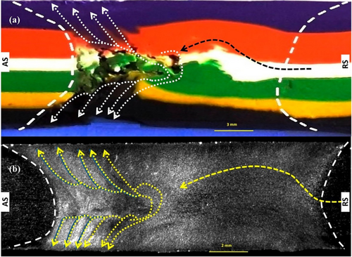
The study of material flow during Bobbin tool FSW employed the Eulerian method to yield a comprehensive understanding of how the material behaves in this manufacturing process [171]. The results reveal distinct material flow patterns in both SAZ and PAZ, emphasizing the different behaviors exhibited in each area. Figure 34a–c, illustrate the material flow patterns at various stages of the welding process, showcasing 3D representations and cross-sectional views. Post-welding, the sheets were separated to facilitate a clearer analysis of the integrated material flow between the two sheets. The visual representations affirm that in the SAZ, the material flow primarily moves from the RS to the AS. Conversely, in the PAZ, the material predominantly originates from the AS, as evidenced by the substantial blue material that envelops the tool pin.
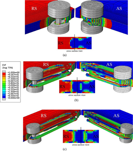
The investigation also examined the impact of different pin profiles on material flow behavior. The trigonal pin, characterized by its long sweeping lever, facilitates the migration of larger volumes of material. However, the hexagonal pin tool outperforms the others by achieving the most uniform material movement and optimal material coalescence. In comparison, the inward conical pin tool produces the weakest material flow patterns, often resulting in tunneling cavities within the welding zone. Conversely, the outward conical pin tool produces a subsidiary material flow that enhances coalescence, ultimately leading to higher strain, minimized grain size, and improved mechanical properties when compared to those achieved with the inward conical pin tool.
To gain a comprehensive understanding of the fundamental physical processes during BTFSW, a CEL model integrated with a point tracking method has been developed in a recent study [172].
The schematic representation of the overall flow model in BTFSW, as illustrated in Figure 35, is primarily governed by circumferential shear flow. The elevated flow velocities observed at both shoulders are associated with the intense shearing effect, resulting in the formation of a funnel-shaped structure (Figure 35a). Initially, the material is transferred relatively quickly, predominantly exhibiting laminar flow characteristics (Figure 35b). However, this initial flow is disrupted by the sudden appearance of a cavity behind the advancing side (Figure 35c).
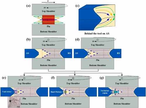
A pronounced velocity gradient across the thickness of the sheet causes the material flowing back around the shoulder to converge at the edge of the advancing side preferentially. This material then continuously moves inward (Figure 35d). Based on this process, the mechanism responsible for the development of typical features on the advancing side is depicted in Figure 35e–g. When the material experiences weak driving forces from the stirring tool while being constrained by the colder metal outside due to insufficient heat input, limited accumulation occurs in the confluence region, failing to refill the cavity completely. Consequently, void defects develop and concentrate on the advancing side (Figure 35e).
As the flow becomes more vigorous, the material within the confluence area undergoes thorough mixing and progressively migrates to the retreating side (Figure 35f). When the confluence region extends toward the retreating side due to enhanced flow, the convergence of multiple strong material flow strands can create a turbulent region, thereby producing discrete voids (Figure 35g).
The entry methods of tools in the Conventional Friction Stir Welding and Bobbin Tool Friction Stir Welding (BTFSW) processes highlight a significant difference in their operational techniques. In CFSW, the welding operation initiates from within the extremities of the workpiece. The rotating pin is plunged perpendicularly into the joint line, and the tool is subsequently removed vertically after completing the weld. This technique effectively prevents material loss during the process.
In contrast, BTFSW tools cannot be plunged directly into the workpiece material. Instead, to facilitate an internal entry point within the plate's boundaries, a pre-existing hole must be created, allowing the tool to be inserted while securing the outer shoulder in position. This procedure can prove to be difficult and may occasionally cause distortion in the workpiece. Furthermore, the requirement to remove material from the weld line can introduce discontinuities at the entry and exit locations of the weld. As a result, the fixed bobbin tool is constructed as a single unit, initiating the welding process from the outer edge of the workpiece. In this scenario, the bobbin tool engages with the material to form a butt joint, with the exit occurring from the material's extremity. When entry and exit occur beyond the material's boundaries, defects may arise.
Both the entry zone and exit zone during BTFSW feature two types of discontinuity defects, and addressing these remains a critical challenge in enhancing weld quality. Research has been conducted to analyze the characteristic features and formation mechanisms of these defects within the weld structure during the BFSW process [173]. In a study, multi-colored plasticine layers were utilized to visualize material flow, serving as an analog to metal flow. By employing different colors as path markers within the analog model, the streamlined flow could be effectively delineated, illustrating the discontinuity defects in comparison to actual metal welds.
Figure 36 illustrates the top surface (Figure 36a) and bottom surface (Figure 36b) of the entry zone from a plasticine sample. It is apparent that the color of the entry spray on both surfaces corresponds to the color of the material on the top and bottom layers of the RS, respectively. As seen, during the initial entry phase of the bobbin tool into the workpiece, the flow of material from the RS to the AS is interrupted, resulting in the outward ejection of the plasticized mass from the workpiece. This ejection phenomenon can be attributed to the free surface at the trailing edge of the tool and the absence of a solidified mass that would typically impede material flow.
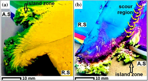
Figure 36b, which depicts the bottom surface of the analog model, reveals the formation of a tunnel void that has evolved into a continuous channel pattern, originating from the entry zone and extending parallel to the weld line, approximately offset by half the diameter of the pin toward the advancing side. The intricate flow fields at the triple junction within the structure of FSW welds can lead to localized discontinuity defects, such as tunnel voids or macro-channels. In certain cases, this disruption may reach the surface, as illustrated in Figure 36b; however, it is primarily observed as a macro-sized internal defect.
Figure 37 further illustrates similar flow characteristics in the exit zone of the analog model. As the tool withdraws from the workpiece, it disturbs the weld body. The arrows shown on the top and bottom surfaces of the workpiece (Figure 37a,b) denote the residual traces of the shoulder on the surface, indicating the material movement from the RS to the AS before the disruption occurs. However, during this phase, the circulation system is unable to maintain its primary flow direction from AS to RS. The end view (Figure 37c) emphasizes the shear layers of the exit zone, capturing the final impressions of the pin threads embedded within the material.
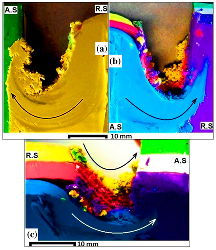
In conclusion, the analog models demonstrate that both the entry and exit zones in BTFSW are affected by the inhomogeneity of the material flow regime, leading to the ejection or disruption of the plastic flow in the gap between the bobbin shoulders. Experiments conducted with aluminum welds indicate that while it may not be possible to completely eliminate entry-exit defects within the weld body, the size of these defects can be reduced by adjusting the welding parameters.
5 Material Flow in SSFSW
Stationary shoulder FSW, a variant of FSW, was introduced by TWI in late 2004 to early 2005 as a method for joining high-temperature, low-thermal-conductive alloys such as titanium alloys [174, 175]. Titanium alloys pose specific difficulties for CFSW due to their elevated softening temperature and poor thermal conductivity. As a result, creating enough heat to adequately soften the material at the weld root, which is close to the pin tip, becomes challenging without inadvertently overheating the weld face beneath the shoulder. In SSFSW, the welding process employs a rotating tool featuring a pin (which may have a small or negligible shoulder) situated within a non-rotating or stationary shoulder that glides over the joint line during the welding operation (Figure 38). This configuration effectively reduces or eliminates heat generated by the shoulder, resulting in lower and more concentrated heat generation throughout the weld thickness.
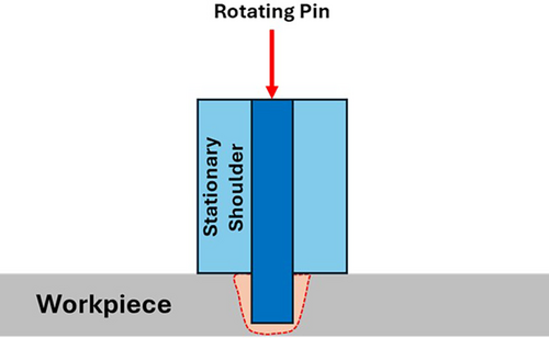
The intrinsic characteristics of SSFSW confer several advantages over conventional techniques. Notably, SSFSW enhances the fatigue life of welds by applying higher compressive stresses and improves both the symmetry of the microstructure and the distribution of hardness [176, 177]. Furthermore, it is capable of producing a variety of joint types, including T-section and corner fillet joints [178]. Welds completed using SSFSW are noted for their superior surface quality, characterized by diminished heights and minimized flash, thus negating the necessity for subsequent finishing processes [179]. Additionally, these joints exhibit increased hardness and tensile strength [180].
Research on material flow models for lap-welded AA2024-T6 using both CFSW and SSFSW at parameters of 1000 rpm and 50 mm/min has been conducted [181]. In the CFSW process, the SZ is divided into a SAZ and a PAZ. Conversely, the SZ in SSFSW is entirely designated as PAZ, indicating that the entire stir zone is encompassed within it.
In SSFSW, the frictionally softened material is propelled from the top to the bottom of the SZ along the helical threads of the pin. The backing plate exerts a forging effect that compresses the accumulated plasticized material toward the joint surface. However, the upward-flowing material often escapes from the SZ in the form of flashes, consequently diminishing effective joint thickness or producing volume defects. The stationary shoulder exerts an additional forging force at the top of the weld, preventing the outflow of plasticized material from the SZ, thereby enhancing material flow within the stir zone. In contrast, CFSW's rotational shoulder provides a relatively lower forging force, allowing the upward-flowing material to gain tangential velocity, further facilitating its escape from the SZ in the form of flashes and weakening the flow intensity within the stir zone.
6 Comparison of Different FSW Methods
The key distinctions among CFSW, SSFSW, and BTFSW processes originate from their respective welding tools, which play a significant role in determining heat input, surface roughness, weld thinning, and microstructural gradients. In both CFSW and BTFSW, the welding tools are directly connected to the machine spindle. However, SSFSW distinguishes itself by utilizing an additional fixed shaft to support its stationary shoulder, which significantly influences the dynamics of the welding process.
The integration of a lower shoulder in BTFSW alters the heat generation dynamics during welding. In CFSW, a majority of the heat is produced by the rotating shoulder, which can lead to a pronounced microstructural gradient and an increased likelihood of defects due to inadequate heating at the bottom of the weld. In contrast, the lower shoulder in BTFSW promotes a more balanced heat input, which contributes to a more symmetrical microstructure and higher peak temperatures. For SSFSW, heat generation is primarily facilitated by the rotating pin, as the stationary shoulder remains fixed, allowing for consistent heat input across the entirety of the weld. Under comparable conditions, BTFSW exhibits a higher heat input than CFSW, while SSFSW presents a lower heat input, enabling higher tool rotation speeds and improved material mixing. The dual rotational shoulders of BTFSW minimize heat dissipation while ensuring a balanced heat input, resulting in an expanded TMAZ and HAZ. In contrast, SSFSW provides uniform heat dissipation and reduced heat input, leading to a nearly imperceptible TMAZ and a smaller HAZ relative to the other techniques.
Furthermore, the morphology of weld joints varies among the three processes. CFSW joints typically exhibit a basin-like shape, whereas BTFSW joints possess an hourglass configuration [182]. These morphological differences arise from the material deformation influenced by the shoulder dynamics specific to each method. The SSFSW joint, on the other hand, features a symmetrical weld morphology characterized by uniform heat input facilitated by the rotating pin throughout the joint thickness [183]. During the CFSW and BTFSW processes, the tool shoulder can create defects known as flashes on one or both sides of the weld [184]. In contrast, SSFSW joints generally display smoother surfaces with minimal to no flashes [185].
7 Friction Stir Processing
Friction Stir Processing is a solid-state technique derived from FSW that enables the modification of the microstructure and properties of metals without melting them. This process utilizes a non-consumable tool equipped with a rapidly rotating pin, which is inserted into the workpiece to generate localized heat via friction. This action facilitates significant plastic deformation, leading to refined grain structures and improved material properties, such as enhanced strength, toughness, and wear resistance [186, 187]. FSP is particularly effective for creating surface composites, rectifying defects in cast materials, and enhancing the performance characteristics of various alloys, including aluminum, magnesium, and stainless steel.
In composite fabrication, FSP enhances the mechanical properties of metals by integrating reinforcement particles into a metal matrix. Initially, these reinforcing particles are embedded in grooves or holes created on the surface of the sample. The tool then redistributes these particles throughout the metal matrix [188]. Typically, multiple passes of the process are employed to achieve a more uniform distribution of the reinforcement particles. Unlike FSW, which focuses on metal joining, FSP prioritizes the uniform distribution of particles in the base metal, making material flow critical.
Numerous studies have explored the distribution of particles within base metals. One investigation examined the effect of tool pin shapes on particle distribution during FSP [189]. Various tool designs, including square, cylindrical, hexagonal, triflate, and triangular pin profiles, were employed to evaluate their influence on the dispersion of reinforcing particles in the base alloy.
It was found that a cylindrical pin profile was ineffective, leading to the agglomeration of the reinforcing particles primarily at the pin's root (Figure 39). This indicates that a circular tool design fails to disperse particles evenly in the metal matrix. In contrast, using a triangular pin profile resulted in a slightly better particle distribution; however, particles were not uniformly spread across the sheet's surface, with low bonding observed due to insufficient vertical material mobility (Figure 39). Conversely, samples created with a square pin showed improved dispersion, as various bands with differing amounts of reinforcing particles were identified within the SZ, attributed to the pin's greater eccentricity and pulsating effect, which encouraged material flow. Ultimately, the hexagonal pin profile led to optimal particle dispersion, with a uniform distribution of particles within the matrix observed throughout the FSPed samples (Figure 39). The composition from the triflate pin demonstrated that, with the exception of areas close to the top sheet surface, particle distribution was satisfactory in the SZ region.
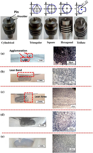
Further investigations into the material flow pattern during FSP utilized CEL modeling to assess how pin thread and thread pitch influenced the distribution of reinforcing particles [190]. Three distinct tool designs with varying thread pitches of 0.75 mm, 1 mm, and 2 mm were evaluated. Results indicated that samples processed with threaded tools experienced higher temperatures and strain levels compared to those utilizing circular tools. The circular tool design failed to ensure uniform particle distribution within the processed zone. However, threaded pins with pitches of both 0.75 mm and 1 mm effectively facilitated a more uniform arrangement of particles in the base matrix, thereby optimizing processing outcomes.
Additionally, the effect of tool pin profiles on reinforcement distribution in B4C/aluminum composites was studied. Samples were fabricated using four passes, with variables introduced by either maintaining or altering the tool's rotational direction between passes [191]. It was found that without changing the rotational direction, particles tended to agglomerate excessively on the advancing side, leading to observable asymmetries in particle distribution across the SZ. As a result, reinforcing particles increasingly migrated to the AS during successive passes, culminating in significant accumulation by the fourth pass. Conversely, altering the rotation direction throughout the different FSP passes prompted a more balanced migration of particles between the AS and the RS, improving overall particle distribution.
In another approach aimed at enhancing particle dispersion, researchers introduced a technique involving the machining of three gradient grooves that increase in depth from the advancing side to the retreating side rather than employing a single groove [192]. The findings indicated that this gradient design led to the most uniform distribution of SiC particles throughout the composite zone.
In another investigation, researchers examined how tool rotational and traverse speeds affect particle distribution during FSP [193]. Figure 40 presents macro-images of the SZ in the FSPed specimens containing reinforcing particles, showcasing various tool rotational and traverse speeds. As illustrated in Figure 40, an increase in the rotational-to-traverse speed ratio correlates with both an expansion of the SZ area and an enhancement in the quality of particle distribution. Conversely, while the increase in SZ area is observed, there is a corresponding reduction in the actual volume fractions of reinforcing particles within the composite layer.
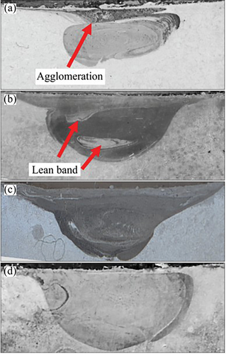
8 Application of Machine Learning Method
Artificial Intelligence methodologies offer a multitude of benefits by allowing algorithms to process large datasets and accurately identify optimal processing parameters, significantly improving weld quality [194, 195]. Among these techniques, machine learning methods have emerged as powerful tools for modeling FSW, thanks to their ability to clarify the relationships between control variables and the responses of the welding process during the training stage. Once these models are adequately trained, they can generalize and predict process responses even under conditions not previously encountered, thereby enhancing adaptability.
In the realm of FSW, there is a growing trend toward applying machine learning to elevate both the quality and efficiency of welding operations. By utilizing ML methods such as Artificial Neural Networks and Support Vector Machines, researchers and manufacturers can forecast ultimate tensile strength, detect weld defects, and monitor processes by evaluating essential parameters like traverse speed, rotational speed, and applied force. The incorporation of machine learning in FSW not only helps in predicting the integrity of the welds but also fine-tunes welding conditions, thereby minimizing defects and enhancing weld consistency.
The implementation of machine learning methods in FSW monitoring has garnered significant attention in recent years, reflecting a transformative shift in the manufacturing landscape. In a study, SVMs are utilized to classify welds based on features extracted from surface images [196]. The welding joints are created under varied conditions by adjusting parameters such as tool rotational speed, traverse speed, shoulder diameter, and pin diameter. Digital cameras capture the resulting weld surfaces generated under these different conditions, and the images are subsequently processed to extract relevant features. The first step in processing the captured images involves selecting the ROI. The ROI refers to the specific portion of the image that provides valuable information through various image processing techniques. In this context, the ROI encompasses the top surface of the weld region, which displays semi-circular patterns. Features from the weld surface images are extracted using the Maximally Stable Extremal Region algorithm, which serves as the input for classifying the weld joints. Each feature vector comprises 320 individual features, with a total of 27 feature vectors available for SVM input. Initially, these feature vectors are divided into two distinct classes: Class 0, which includes feature vectors from images of good welds, and Class 1, which consists of feature vectors from images exhibiting defective welds. The Support Vector Machines are trained using various kernel functions, revealing that linear and quadratic kernel functions classify good and defective welds with an accuracy rate of 95.8%.
A strategic approach has been proposed to create force-data-driven machine learning models explicitly designed to predict defects and categorize their types in FSW [197]. This approach involves extracting 30 force-related features from both the frequency and time domains using the Fast Fourier Transform along with other computational techniques. The importance of these features is evaluated using information gain analysis, enabling a ranking of features based on their relevance to defect formation in FSW joints. Remarkably, the average force in the Y-direction was identified as the most crucial factor affecting defect occurrence.
A model based on ANN was combined with a multi-sensor methodology to effectively manage and monitor the FSW, aiming to minimize the chances of weld defects [198]. The proposed model is illustrated in Figure 41. This system is engineered to collect data from various sensors linked to the FSW machinery, relaying crucial metrics such as force, torque, and power to a cloud platform. An ANN processes the collected samples utilizing digital signal processing techniques, enabling the extraction of vital features necessary for real-time predictions of UTS. The model forecasts UTS values and benchmarks them against pre-established standards. If the predicted UTS does not meet the desired target, a second ANN formulates new parameters focused on improving weld quality; on the other hand, if the predicted UTS is satisfactory, the system maintains the current parameters.
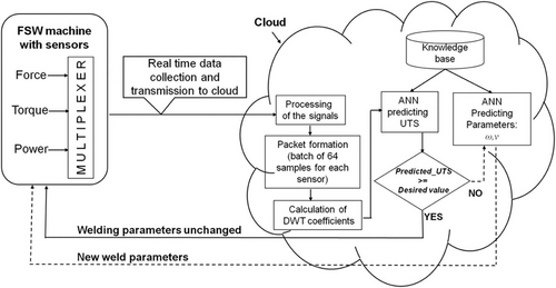
9 Outlook
FSW is recognized as a well-established joining process; however, significant challenges related to material flow continue to present compelling issues for researchers. A thorough understanding of these challenges is vital for improving process control and developing dependable numerical models. Considerable efforts have been directed toward creating experimental techniques to investigate material flow during FSW. Nonetheless, each technique introduces specific difficulties that hinder the accurate evaluation of material flow. One promising avenue of research involves the development of methods for on-line monitoring of material flow, which could offer real-time insights and enhance overall process comprehension.
Numerical modeling has gained popularity among researchers, showcasing substantial capabilities in depicting material flow characteristics. However, issues such as defect formation and dissimilar welds underscore the necessity for further exploration. To enhance existing 3D numerical models, it is critical to investigate the key factors affecting material flow, including the interaction between the tool and the heated workpiece, particularly the mixed stirring and extrusion processes, as well as the nature of contact at various interfaces, including sticking and sliding behaviors.
Research has revealed the distinct roles of the pin and shoulder in FSW, with the interaction between the flows generated by these components representing a complex phenomenon that poses challenges for experimental study. This chaotic transition zone is essential for understanding weld quality and can be more effectively analyzed through advanced 3D finite element models. While much of the research has concentrated on circular or threaded tools, there is an urgent need to explore material flow in more complex pin geometries. The parameters affecting material flow warrant more comprehensive investigation, as many existing studies are conducted under specific conditions, limiting the applicability of their findings to broader scenarios.
Recent advancements in FSW variants, such as Bobbin Friction Stir Welding and Stationary Shoulder Friction Stir Welding (SSFSW), introduce additional complexities. The mechanisms of material flow in these innovative processes remain poorly understood, necessitating further research to examine their unique characteristics and behaviors. In conclusion, although FSW is a well-established process, the complexities of material flow continue to be an active area of inquiry. Addressing the challenges associated with experimental techniques, numerical modeling, tool dynamics, and emerging welding variants is crucial for enhancing our understanding and improving the reliability of FSW processes.
10 Conclusion
In this comprehensive review, the phenomenon of material flow during FSW has been meticulously analyzed, beginning with an overview of the diverse methodologies used to investigate this critical aspect of welding technology. Two primary approaches—experimental and numerical methods—are examined in detail to understand material flow throughout the welding process. The discussion highlights the intricate dynamics of material flow, focusing on the essential interactions between the welding tool and the workpieces. Key processes, such as the filling cavity mechanism, are thoroughly explored, alongside an analysis of defect formation and the various challenges associated with it. Multiple factors influencing material flow are identified, including welding tool design, rotational speed, traverse speed, and tilt angle. Beyond traditional FSW techniques, this review also provides insightful discussions on advanced variants such as BTFSW and SSFSW. These innovative methods are assessed for their unique functionalities and the distinct characteristics they introduce to the material flow process, underscoring their relevance for future research and practical applications in the welding industry.
To effectively investigate material flow during FSW, it is essential to define and discuss the various flow regimes involved. Material flow can be complex, arising from the unique mechanics of the welding process, which involves interactions between the tool and workpieces. Four distinct material flow regimes are typically observed, particularly noting the differences on the advancing and retreating sides of the joint, as well as the pin-affected zone and shoulder-affected zone.
The exploration of contact state conditions in FSW has significantly advanced our understanding of tool-workpiece interactions, particularly through the concepts of sticking and sliding. Initial studies established a foundational framework, while subsequent investigations utilizing high-frequency x-ray imaging and torque monitoring provided empirical evidence of mixed sticking/sliding conditions. Various experimental methodologies have been employed to discern whether stirring, extrusion, or a combination of both occurs behind the pin during FSW. However, inconsistencies in the literature persist, as similar welding configurations have led to differing conclusions regarding the dominance of stirring or extrusion. A comprehensive perspective suggests that both mechanisms likely coexist within the mid-thickness of a thick FSW plate, with stirring prevailing in the upper region due to the shoulder's action and extrusion dominating at the bottom due to the pin's influence.
The influence of effective process parameters—such as tool geometry, rotational and traverse speeds, and tilt angle—on material flow has been thoroughly investigated. Different pin shapes have been established to promote specific material flow patterns; for instance, threaded surfaces encourage vertical motion. The characteristics of the tool shoulder also significantly affect material flow, with increased stirring observed through the use of a scrolled shoulder. Furthermore, the end surfaces of the shoulder—whether flat, concave, or convex—play a role in influencing material flow throughout the process. Preheating treatments have been shown to enhance the flow velocities of plastic materials and reduce differences in flow velocities during the FSW of dissimilar alloys. Research indicates that tool tilt angle significantly enhances the migration of tracer particles in both vertical and horizontal directions, reflecting a more dynamic material flow during the FSW process.
Author Contributions
Mostafa Akbari: conceptualization, investigation, writing – review and editing, writing – original draft, project administration, supervision. Amin Abdollahzadeh: supervision, writing – review and editing. Milad Esfandiar: supervision, writing – review and editing.
Conflicts of Interest
The authors declare no conflicts of interest.
Open Research
Data Availability Statement
Data sharing is not applicable to this article as no new data were created or analyzed in this study.


