Analytical Solution for Railway Transition Zones With Abrupt Changes in Elastic Stiffness
ABSTRACT
Transition zones in railway systems, where properties of the track foundation change abruptly, are known to increase dynamic loads, track deterioration, and passenger discomfort. As such, it is of particular importance to study railway transition zones with abrupt changes in foundation properties to minimize these railway problems. This paper presents a closed-form solution for the long-term deformation of an Euler-Bernoulli beam on an elastic foundation with multiple abrupt changes in foundation stiffness and under multiple applied stationary point loads. The solutions are obtained by dividing the beam into segments and applying the method of undetermined coefficients. This exact analytical solution constitutes an improvement upon an approximate solution, which is presented in the literature as a recent method for modeling rail infrastructure at transition zones. A limitation of the approximate solution is its inability to account for the changed behavior of the beam close to a transition zone. The closed-form solution overcomes this limitation and can be used to assess the suitability of the approximate solution.
1 Introduction
The need for increasingly efficient railway systems, driven in part by rising populations, is ever present and continuously driving innovation and improvement [1]. This is no less true for Australia and its approximately 30,000km long rail network [2]. In some areas, Australia is playing a leading role, for instance with heavy haul rail networks [3] but is lacking in other areas, such as the uptake of high-speed networks (Australia's trains being limited to a maximum of 160km/h) [4]. In either case, this motivates research into methods for analyzing and improving railway infrastructure.
Infinite beam-on-elastic-foundation models have been used to study railway tracks since at least 1888 [5], having also been applied in a variety of other fields [6-8]. In classical formulations, the foundation is assumed to be homogeneous under the entire length of the beam, however, in practice this is frequently an oversimplification and more recent work has also considered inhomogeneous foundations. A rail line, for instance, may experience an abrupt change in foundation stiffness when moving between a soil subgrade and a concrete foundation associated with a bridge or culvert. Inhomogeneities such as these are commonly referred to as “transition zones” [7, 9-11]. Plastic deformations accumulate at different rates across the transition zone creating differential settlements, which increase dynamic loads on the track, track deterioration, and passenger discomfort, thereby necessitating more frequent maintenance [7, 12]. Research into approaches for mitigating the differential settlement across transition zones is ongoing and motivates a better understanding of the mechanics of the system [7, 12-20]. For a detailed review of the literature surrounding transition zones, we refer the reader to works by Sañudo et al. [16], Indraratna et al. [21], and Fortunato et al. [22].
Experimental work has established methods for determining foundation properties [23-26] and investigating expected behaviours of the track at transition zones [9, 25, 27, 28], however, beyond this, investigations have largely been limited to numerical modeling [21] such as spectral Galerkin methods [29] and finite element methods, many of which are validated against empirical data. Finite element approaches have been particularly widely used, as they are effective at modeling the basic one dimensional case [10, 30], as well as more general two [31-33] and (most effectively) three [10-12, 27, 34-40] dimensional cases. Additionally, they can be more easily extended to non-linear theories, involving considerations of plastic deformations [34, 40, 41]. The most significant limitation of numerical methods is large computation times, which become particularly problematic when attempting to optimize track parameters. Recent research has worked to address this problem through the use of surrogate-assisted methods [30, 42, 43].
Although analytical solutions to some models do also exist [44-46], many are limited to finite beams [47-49], though others leverage a periodic track structure [33, 50-53]. In the absence of a transition zone, the steady-state deformation of the beam may easily be found using general solutions [44]. This is the basis for the approach taken by Sajjad et al. [7], who attempt to solve for the beam deformation around transition zones by superimposing solutions from multiple beams, each with a different uniform foundation stiffness. The recovered deformations are then used to inform the iterative design of multi-step transition zones. Whilst this approach is validated against numerical modeling for the cases considered in Reference [7], the solution obtained is only an approximate solution to the proposed model so it may not be valid under different conditions or changes to parameters. Also, it is important to note that the model only considers stationary loads. Dynamic amplification, which is considered to be important to the analysis of transition zones [19], is not directly present in this model. However, Sajjad et al. [7] multiply deformations by a dynamic amplification factor to account for this limitation.
The purposes of this paper are two-fold. The first is to respond to an absence in the literature of readily available, closed-form solutions for the steady-state deformation of an Euler-Bernoulli beam on a piece-wise homogeneous foundation with an arbitrary number of static point forces and foundation discontinuities (the model considered by Sajjad et al. [7], details of which are given in Section 2.1). Secondly, to apply the analytical solution to investigate the accuracy of the approximate solution proposed by Sajjad et al., which is summarized here in Section 2.2.
The derivation of the analytical solution is given in Section 2.3, wherein we divide the solution domain into homogeneous segments to which we can apply the method of undetermined coefficients. We then combine individual solutions by enforcing continuity conditions at the boundaries. Notably, this is similar to the method used in Reference [6] for a sinusoidal applied load in the context of subterranean tunnel design and the classical methods in Reference [5].
Enforcing the boundary conditions leads to a linear system of variables for the coefficients of the general solution, where is the number of beam segments (MATLAB code for constructing this matrix and solving for the deformation of the beam is provided in the Supporting Information). Recovering the solution to the system is then reduced to solving the linear system. Notably, for large systems, the matrices may be close to singular, and more advanced solution techniques may be required to improve accuracy. This is an avenue of further research and is not treated here.
A comparison between the approximate and analytical solutions is presented in Section 3. First, the effect of varying placement of point forces relative to transition zones is considered, specifically to highlight a limitation of the approximate solution. Following this, a comparison is also presented between the approximate and analytical solutions within the context of the graduated transition zones considered in Sajjad et al. [7]. Concluding statements are given in Section 4, followed by some remarks concerning the model itself in Section 5.
2 Governing Equations and Solutions
2.1 Governing Equations
| Position along the axis of the beam. (m) | |
| Vertical deformation of the beam. (m) | |
| Approximate vertical deformation. (m) | |
| Young's modulus of Elasticity. (N/m) | |
| Moment of Inertia. (m) | |
| Foundation stiffness. (N/m) | |
| Strength of applied load. (N/m) | |
| Position of applied load. (m) | |
| Number of beam segments. | |
| Number of boundaries. | |
| Length of graduated transition zone. (m) | |
| Starting position of th gradation in graduated transition zone. (m) | |
| Total change in foundation stiffness across the graduated transition zone. (N/m) |
2.2 Approximate Solution
2.3 Analytical Solution
To solve Equation (6), we make the observation that it is a linear and piece-wise constant coefficient. Hence, by dividing the domain into (possibly semi-infinite) segments, whose boundaries are prescribed by the coordinates of the transition zones and point force, we can reduce the problem to an ordinary differential equation with constant coefficients. Then, we can apply the method of undetermined coefficients and create a full solution by enforcing continuity conditions at the boundaries between each segment.
From this, it remains to solve for the coefficients , which is simply done by implementing boundary conditions at positions and forming a system of linear equations. At transition zones that do not coincide with a point force, we enforce the continuity of the solution and its first three derivatives. At a point force (on a transition zone or otherwise) we enforce the continuity of the function and its first two derivatives. Continuity of the function at a point force implies a discontinuity of the third derivative proportional to the strength of the point force (see Appendix B). The equations arising from implementing these conditions can be found in Appendix C.
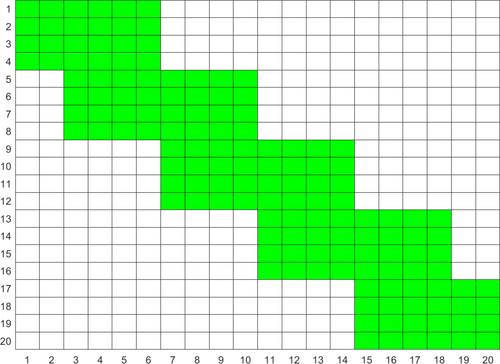
We note that the construction of the matrix and the right-hand-side vector within a computer program is not a trivial process. This is especially true if the goal is to be able to quickly input an arbitrary set of transition zones and point forces. The provided MATLAB code, in the Supporting Information, includes a purpose-built class that contains all the methods we expect to be commonly required.
It is also worth noting that each additional boundary (i.e., point force, transition zone, or coinciding transition zone and point force) adds four rows and columns to matrix . In this way, solving for each point force and then superimposing serves to limit the size of the matrices that need to be inverted. The described method may be easily extended to calculate the displacement for all point forces simultaneously, if that is desired, or for abrupt changes in beam stiffness . These cases, however, are not dealt with in this paper nor are they implemented in the MATLAB code in the Supporting Information.
3 Comparison Between Analytical and Approximate Solutions
In this section, we compare the beam deformations as predicted by the approximate solution to those of the closed-form solution. This is with the goal of providing insight into the behavior of the approximate solution.
The broad behavior of the approximate solution was presented in Reference [7] and validated against numerical models for the relevant use cases. Here we consider cases chosen to display situations in which the approximate solution may not approximate the model. Specifically, we look at the case of a single point force placed close to a transition zone (Section 3.1), and the behavior of the approximate solution as the number of gradations is increased for a graduated transition zone as in Equation (14) (Section 3.2). Notably, throughout this section, we choose to report the absolute errors or strict differences between the analytic and approximate deformations in preference over relative errors. This is done to give a sense of the scale of the errors to the dimensions of the track infrastructure.
The parameters used for the analysis in this section are chosen to correspond to those for which the approximate method was validated in Reference [7]. The Young's modulus of the beam is given as N/m, the moment of inertia can be calculated from the geometry of the beam cross-section as m, chosen to correspond to UIC60 rail [7], and the strength of the applied load can be calculated to be N/m which corresponds to a 10 t load. The values of the foundation stiffness vary throughout the section and are given as used.
3.1 One Transition Zone
In the absence of transition zones, the approximate solution developed in Reference [7] gives results that are algebraically equivalent to the method described in this paper, as a consequence of both methods being an implementation of preexisting general solutions. The results begin to differ, however, as transition zones are introduced. In this section, we analyze the discrepancy between the closed-form solution and approximate solution for varying placements of a point force and with a transition zone at , over which the foundation stiffness changes from to .
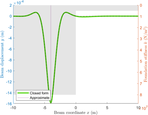
Figure 2 shows the closed-form solution plotted against the approximate solution for a point forced placed 4 meters from the transition zone. The two approaches match well over the entire plot, differing most significantly near the transition zone. Given that the approximate solution only uses the stiffness where the point force is applied, and hence does not consider the transition zone, this behavior is expected.
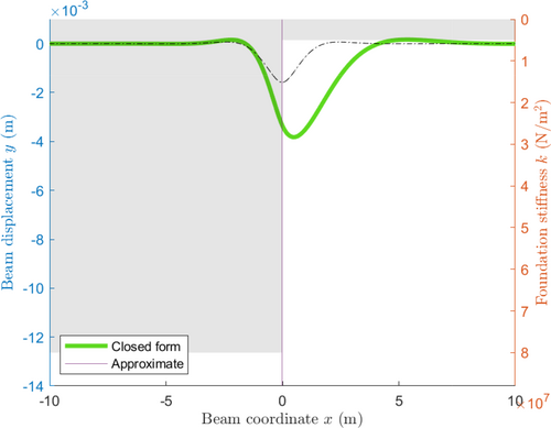
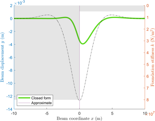
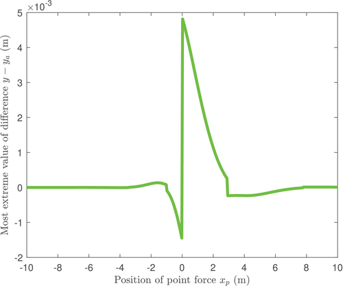
Following this argument, it is expected that the two solutions will differ most significantly when the point force is close to the transition zone. Furthermore, a small change in the placement of the point force across a transition zone should cause only a small change in the displacement of the closed-form solution but will result in abrupt and significant changes in the approximate solution. This phenomenon is demonstrated in Figures 3 and 4, where significant differences between the two approaches are readily observed (approximately 1–6 mm). To the left of the transition zone, the maximum deformation is significantly underestimated by the approximate solution as it fails to take into account the nearby region of low stiffness and conversely to the right of the transition zone. This is illustrated more precisely in Figure 5, which shows the most extreme value of the difference between the analytical solution and approximate solution, , for various values of the position of the point force and with a transition zone at . As previously mentioned, away from the transition zone, the difference between the two approaches is negligible. The difference gradually increases closer to the transition zone before abruptly changing as the point force moves from being applied on the stiffer beam segment to the less rigid segment. Around the transition zone, the error reaches a high of approximately 5mm, close to 2.5 times the predicted deformation from the analytical solution. There are also smaller abrupt changes present at and 3 which are associated with a change in sign when the most extreme value changes between being associated with an under-approximation (over-approximation) at the transition zone and being associated with an over-approximation (under-approximation) at the point force. Another observation we can make here is that, for the approximate solution, the maximum deformation occurs precisely at the point force. For the analytical solution however, the maximum deformation is offset, which aligns more closely to the behavior of 3D finite element models, as can be seen in Reference [35].
3.2 Graduated Transition Zone
| −29.75 | −27.25 | −15.25 | −12.75 | −8.75 | −6.25 | 5.75 | 8.25 |
| 12.25 | 14.75 | 26.75 | 29.25 | 33.25 | 35.75 | 47.75 | 50.25 |
Figures 6-8 show the deformation of the beam as the number of gradations in the graduated transition zone is increased. Notably, we see similar behavior as occurred with a single point force and transition zone. That is, the most significant differences occur at the transition zones, especially when a point force is close to the transition zone. A markedly higher deformation at approximately m is related only to the closer proximity of the point forces at and , as compared with the other point forces.
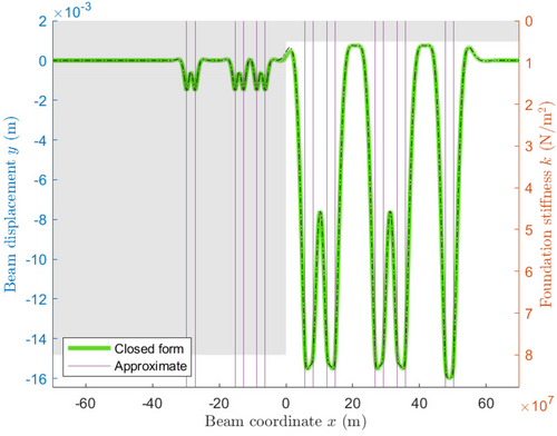
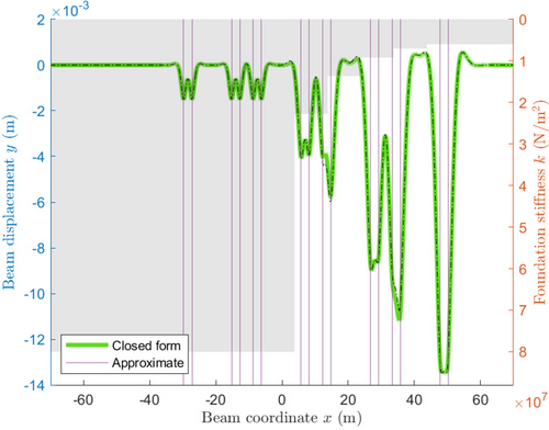
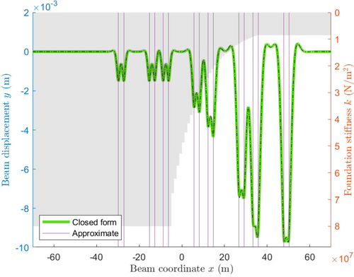
Comparing Figures 6 and 8, the agreement between the two approaches appears to improve as the number of transition zones increases. At certain points, however, the difference may increase significantly, as illustrated by Figure 7, specifically at and . Figure 9, which graphs the most extreme absolute difference between the closed-form and approximate solutions for an increasing number of transition zones, shows this trend for the system described here. As the number of additional transition zones (i.e., gradations) is increased, the absolute difference between the analytical and approximate solutions is unstable, but generally decreases. After adding approximately 25 transition zones, the instability is no longer observable, and the difference begins to converge to and oscillate around, approximately m. The early erratic behavior of this graph can be attributed to the proximity of transition zones and point forces. Due to the process by which transition zones are added, the positions of all but the first transition zone change. As such, the difference between the two approaches may increase sharply if a transition zone moves close to or is added near a point force. This effect is most notable when there are few transition zones, and relative positions change by larger amounts to fit evenly within the space. On the other hand, the gradual decrease in error is associated with the gradual decrease in the difference in stiffness across each transition zone. As the change in stiffness becomes spread over a larger area, so too do the errors associated with the approximate solution. This reduction holds only to a point, however. More research is necessary before a conclusion can be made, although it would appear that, in the limiting case, the analytical solution approaches the correct value for a smooth transition (as opposed to piece-wise), while the approximate solution does not.
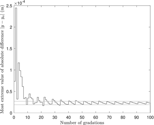
The approximate threshold value of 25 transition zones and limiting error of m are dependent on the parameters of the model and hence cannot be used as rules. While specific results relating to convergence properties are beyond the scope of this paper, some general comments can still be made. The broad properties displayed in Figure 9 and discussed above hold for small changes to the position of the point forces and significant changes to the magnitudes of the parameters and with deformation magnitudes scaling at approximately the order of the fourth derivative of the parameters in this latter case. For the axle load , the deformations and errors both scale directly—that is, a doubling of the axle load will result in a doubling of all deformations. Rigorous analysis of the convergence properties of the approximate solution to the closed-form solution under varying conditions is an avenue for future study.
4 Conclusion
Abrupt changes in foundation stiffness underneath rail track can create differential plastic settlements, which increase dynamic loads, track deterioration, and passenger discomfort, thereby necessitating more frequent maintenance [7, 12]. This motivates research into the deformation of rail tracks around these transition zones. Responding to an absence in the literature of readily available closed-form solutions for the steady-state deformation of an Euler-Bernoulli beam on a visco-elastic foundation, with multiple abrupt changes in stiffness and point forces, we developed such a solution. The deformation is found in terms of the solution of a linear system by splitting the beam into homogeneous segments and enforcing continuity conditions at the boundary. Using this solution, we carried out an analysis of a previously published technique [7], and drew particular attention to situations in which it may have larger errors. Specifically, this was found to be when point forces are close to transition zones and is highest when a point force is placed on the less stiff side of the transition zone where the error was observed to reach a high of approximately 5mm, close to 2.5 times the predicted deformation from the analytical solution. The error in the approximate solution was also assessed as it related to the use of the graduated transition zones for which it was used in the original publication [7]. For low numbers of intermediary transition zones (i.e., approximately 0–10), the errors fluctuate but stayed below m, before decaying in an oscillatory manner to less than m.
Ultimately, the approximation technique presented by [7] is an effective method for rapidly estimating the beam deformation, but may not adequately approximate the model under certain conditions and should be applied with careful consideration. The closed-form solution improves the solution method used by Sajjad et al. [7] in that it provides more accurate results to the model studied in this paper.
5 Remarks on Current Model
Mathematically, the closed-form solution presented in this paper is derived based on analysis of stresses and motion equations coupled with elastic behavior. Even though it provides a more accurate solution in attempts to model railway tracks and transition zones compared to [7], there are limitations of the model (i.e., Euler-Bernoulli beam theory) in capturing the properties at the transition zones. The Euler-Bernoulli beam equation with visco-elastic foundation, and the related static equation, are dependent on elastic theories whereas the constitutive behavior of materials in transition zones is not. As the settlement in transition zones is elasto-plastic and dependent on the behavior of materials used to fill the zones, the deformation may be irrecoverable under the heavy axle loads of freight trains. The analysis in this paper complies only with small-strain and small-displacement theories, while, in reality, the deformations conform more accurately to large-strain and large-displacements theories. The treatment of more accurate elasto-plastic models for analytical progress is a subject of future research. Nevertheless, we refer the reader to recent work in this space using finite element methods such as [27, 32], and also to [21], which presents a review of research into the modeling and improvement of transition zones.
Author Contributions
Josiah Murray: investigation; conceptualization; writing – original draft; writing – review and editing; visualization; validation; methodology; software; formal analysis; data curation. Michael H. Meylan: conceptualization; investigation; methodology; formal analysis; supervision; software; validation; visualization. Trung Ngo: conceptualization; writing – original draft; data curation; resources; software; methodology; validation; funding acquisition; visualization. Ngamta Thamwattana: conceptualization; writing – original draft; writing – review and editing; funding acquisition; visualization; project administration; supervision; resources; formal analysis. Buddhima Indraratna: writing – original draft; resources; project administration; funding acquisition; conceptualization; validation; methodology; visualization.
Acknowledgments
The authors are grateful to the Australian Research Council for the funding of Discovery Project DP220102862.
Conflicts of Interest
The authors declare no conflicts of interest.
Appendix A
Appendix B
Appendix C
Open Research
Data Availability Statement
The data that supports the findings of this study are available in the Supporting Information of this article.


