A Comparative Study of One-Step and Multi-Step Numerical Methods for Solving Ordinary Differential Equations in Water Tank Drainage Systems
ABSTRACT
Numerical methods are essential for solving differential equations in applications such as water drainage systems, where precise water level control is critical for industrial and environmental processes. This study compares one-step numerical methods naming explicit Euler, implicit Euler, implicit midpoint, modified Euler, and fourth-order Runge-Kutta (RK4) with multi-step numerical methods, including Adams-Bashforth, Adams-Moulton, and Predictor-corrector schemes, to solve ordinary differential equations for water tank drainage systems. The analysis focuses on accuracy, stability, computational efficiency, and optimal step size selection. MATLAB scripts and Python (Google Colab) were used to evaluate each method's performance by calculating local and global errors, with detailed analyses of error versus step size, error versus computational effort, and computational effort versus step size. The results reveal that multi-step numerical methods provide superior accuracy and stability for long-term simulations but require greater memory resources, whereas one-step numerical methods are computationally faster but sensitive to step size selection, significantly influencing solution accuracy. This study offers practical recommendations for selecting numerical methods based on application-specific requirements, providing insights into optimizing numerical approaches for systems requiring precise water level control and balancing accuracy with computational efficiency.
1 Introduction
Numerical methods are essential mathematical tools used to solve complex nonlinear systems that are difficult to address analytically. These methods are widely applied across various disciplines, particularly in engineering, where they are indispensable for analyzing fluid flow dynamics and solving related problems [1, 2]. Additionally, in engineering fields such as civil engineering, industrial systems, environmental management, and urban infrastructure, numerical methods play a crucial role in designing efficient systems, such as stormwater management networks, wastewater treatment plants, and industrial reservoirs. Proper water drainage design is vital for resource management and risk mitigation [1, 2].
With the advent of more affordable and efficient computer resources, numerical methods have become increasingly practical and widely adopted. The demand for accurate computational techniques is high, making numerical methods indispensable tools for solving complex problems across various fields. One significant area where numerical methods are applied is the draining process of water tanks, which involves nonlinear dynamics requiring advanced computational techniques. Accurate modeling of water drainage enables the prediction of flow patterns, optimization of tank geometry and outlet configurations, and the management of transient and steady-state conditions [3, 4]. Moreover, the increasing affordability of computational resources has made numerical solutions more practical, allowing researchers and engineers to explore the complexities of these problems in greater detail [5].
Numerical methods are indispensable for solving the ordinary differential equations (ODEs) that govern the dynamics of fluid systems. These systems often exhibit complex, nonlinear behavior, requiring sophisticated computational techniques for accurate modeling and simulation. Furthermore, as computational power continues to increase, these methods are becoming increasingly important in applications such as predicting the behavior of stormwater systems, optimizing water tank drainage processes, and simulating other fluid systems [6, 7].
In the context of water tank drainage, the ODEs governing the system describe the rate of change of the water level in the tank, which depends on factors such as tank geometry, outlet size, and fluid properties. Numerical solutions are needed to model these dynamics accurately and efficiently. Additionally, the choice of numerical method is crucial for ensuring the reliability and accuracy of these simulations. For instance, while one-step methods are often simple and efficient, multi-step methods may offer better stability and accuracy for long-term simulations of water tank drainage [8, 9].
The solution of ODEs in fluid dynamics and water drainage problems typically involves two primary classes of methods: one-step methods and multi-step methods [8, 10, 11]. One-step methods, such as Euler's method and Runge-Kutta methods, solve the ODE using information from the current time step only [7]. On the other hand, multi-step methods, such as the Adams-Bashforth and Adams-Moulton methods, utilize information from multiple previous time steps to achieve more accurate solutions [6].
One of the simplest numerical methods, Euler's method, is widely used for solving first-order ODEs due to its simplicity and ease of implementation. However, Euler's method suffers from accuracy limitations, especially when dealing with stiff equations or long-term integration [7-12]. For these reasons, more sophisticated methods, such as the Runge-Kutta (RK) methods, were introduced to improve the accuracy and stability of the Euler method. The fourth-order Runge Kutta (RK4) method, in particular, strikes a balance between computational efficiency and accuracy, making it widely used in fluid dynamics simulations [1, 13].
The RK4 method has been shown to be highly effective for solving nonlinear differential equations, particularly in fluid flow problems [13]. However, while these methods offer improved accuracy over Euler's method, they still face challenges in terms of stability, especially when modeling stiff equations or performing long-term simulations [7]. Therefore, one-step methods are often insufficient for more complex and stiff problems encountered in fluid dynamics.
Multi-step methods, such as the Adams-Bashforth explicit methods and the Adams-Moulton implicit methods, use information from previous time steps to generate more accurate solutions. These methods are especially advantageous for stiff equations and long-term integrations, where one-step methods may fail to provide accurate or stable solutions [6, 14]. Moreover, the combination of explicit and implicit methods, such as the predictor-corrector approach, exploits the strengths of both methods [6]. This combined approach has been shown to provide an effective balance between accuracy and computational efficiency, making it well-suited for large-scale simulations of fluid systems [14, 15].
Although one-step methods, such as the Euler and RK4 methods, are often preferred for their simplicity and versatility, multi-step methods are favored for their superior accuracy and stability, especially in long-term simulations and stiff problems. A comprehensive comparison of these methods in the context of water tank drainage is essential to understand their strengths and weaknesses under different conditions [16].
In previous works, studies such as [17] and [18] have compared various Runge-Kutta methods, including explicit and implicit approaches, for solving ODEs. While these studies have emphasized the superior accuracy of multi-step methods, a gap persists in comparing one-step and multi-step methods, particularly regarding the relationships between error and computational effort, error and step size, and computational effort and step size, specifically in the context of water tank drainage problems. Additionally, the interplay between method selection, computational effort, and accuracy in real-world applications remains insufficiently explored. This study aims to fill a critical gap in the existing literature by conducting a comparative analysis of one-step and multi-step methods for solving the ODEs governing water tank drainage. Moreover, the research will focus on evaluating key metrics, such as accuracy, stability, and computational efficiency, providing practical recommendations for selecting appropriate numerical techniques for similar engineering applications.
The motivation for this study stems from the need for accurate, efficient, and reliable numerical methods to model and simulate physical systems, particularly water tank drainage systems. These systems are prevalent in various real-world applications, such as water resource management, urban drainage systems, and industrial fluid processes, where precise predictions of water levels and flow rates are crucial for optimal operation and decision-making.
Furthermore, by comparing one-step and multi-step methods, this research aims to provide insights into the strengths and limitations of each approach, thereby guiding engineers and scientists in selecting the most suitable method for their specific problems. Additionally, understanding the trade-offs between stability, computational efficiency, and accuracy is essential for advancing the development of robust algorithms applicable to a wide range of engineering and scientific fields.
This study aims to implement numerical solutions for water drainage problems using one-step and multi-step methods. It evaluates their accuracy, stability, and computational efficiency, focusing on the relationships between error, computational effort, and step size. Additionally, it identifies each method's strengths and limitations and offers recommendations for selecting suitable numerical techniques for similar engineering applications.
This article contributes to the existing literature by offering a comprehensive comparative analysis of one-step and multi-step methods for solving the ODEs governing water tank drainage. Furthermore, the findings emphasize the necessity of balancing accuracy, stability, and computational efficiency in numerical simulations, providing a robust framework to help engineers and researchers optimize numerical techniques for real-world applications.
The article is structured as follows: Section 2 covers the methodology and details the mathematical modeling of the drainage process. Section 3 presents the algorithmic implementation of numerical methods and results analysis. Section 4 discusses and compares the methods, highlighting their strengths and weaknesses. Section 5 concludes with key insights, practical implications, and future research directions. The final section lists the references, providing a comprehensive bibliography.
2 Methodology
The methodology used to solve the ODEs governing the water tank drainage system involves MATLAB simulations and the implementation of various numerical methods using MATLAB scripts, Python Google Colab and run algorithms for each method, varying the step sizes to analyze their impact on accuracy and analyze stability region of each method. The methodology involves selecting appropriate numerical solutions, formulating and simulating a mathematical model, implementing suitable numerical methods and performing a comparative analysis based on performance metrics. The subsequent subsections explain each step of the methodology in detail.
2.1 Numerical Methods
- I.
Formulate the ODE for the water drainage process and simulate it in MATLAB Simulink.
- II.
Determine the time required for the complete drainage of the tank, which helps to obtain the final time in our numerical algorithm.
- III.
Numerically solve the differential equation using the following methods:
- a.
One-step methods: one-step numerical methods are a class of techniques that use the solution from the current step to compute the solution for the next step. These include:
- i.
Euler's methods: explicit (forward), implicit (backward), implicit midpoint, and modified Euler's (Second-order Runge–Kutta (RK2)).
- ii.
Fourth-order Runge–Kutta (RK4) methods.
- i.
- b.
Multi-step methods: multi-step numerical methods are a class of techniques that use information from multiple previous steps to compute the next step. These include:
- i.
Adams-Bashforth explicit methods/open formulas methods (2nd–5th order).
- ii.
Adams-Moulton implicit/closed formulas methods (2nd–5th order).
- iii.
Predictor-corrector methods.
- i.
- a.
The water tank draining process was mathematically modeled and simulated using MATLAB Simulink. The numerical solutions for each method were derived and discussed in detail in separate Section 3. This includes a concise overview of the methods used to address the water tank draining problem.
2.2 Mathematical Model of Drainage Systems for Water Tanks
Mathematical modeling is a fundamental tool used to describe, analyze, and simulate drainage systems, including the drainage of water tanks. Using mathematical equations, engineers can simulate water level behavior, predict drainage rates, estimate draining times, and optimize system parameters as needed [19, 20]. This modeling is particularly crucial in scenarios where precise water level control is essential, such as in chemical processing operations, bottling industries, and water tanks and reservoirs [21].
In scenarios where precise water level control is vital, such as in liquid reservoirs, wastewater treatment plants, bottling industries, and industrial tanks, mathematical models are pivotal for predicting water level dynamics to prevent overflow or depletion risks [19, 20].
The following outlines presents an explanation of the mathematical model for the water tank drainage system and the problem formulation, as depicted in Figure 1.
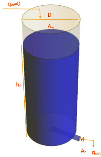
Before formulating the mathematical equations for the water tank drainage problem, several assumptions are considered to simplify the modeling process:
- a.
Constant cross-sectional area: assume that the tank maintains a consistent cross-sectional area which simplifies volume calculations based on the water's height
- b.
Uniform flow: assume a uniform flow rate of water exiting the tank simplifies the modeling of the outflow.
- c.
Negligible friction and turbulence: assuming negligible friction and turbulence aids in mass balance calculations.
- d.
Steady-state conditions: assume a steady-state conditions that the drainage process stabilizes, which simplifying differential equations.
- e.
Constant gravitational acceleration: assuming constant gravitational acceleration is valid for small heights.
- f.
Cylindrical tank with water stored inside: the inlet volumetric flow rate is assumed to be zero.
- g.
Constant atmospheric conditions: assuming constant atmospheric conditions simplifies mathematical equations.
- h.
Constant liquid density: assuming constant liquid density eases the analysis and solution of differential equations.
These assumptions simplify the mathematical modeling process for water draining from a tank [21, 22].
- –
: The inlet volumetric flow rate is assumed to be zero.
- –
: Water level in
- –
: Water level in
Mass Balance:
Unit Balance: Therefore, the units are compatible.
2.3 Process Variable Constraints and Model Validity
2.4 Selection of Initial/Boundary Conditions and Operating Points for Simulation
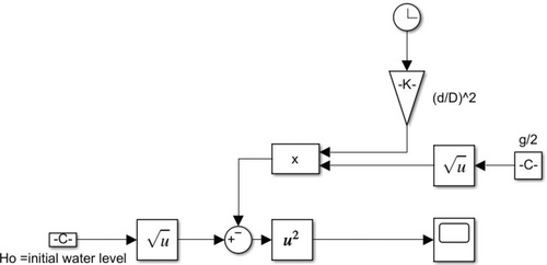
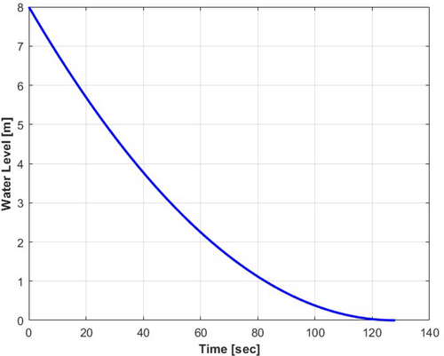
The initial water height is , and the inflow rate is . The selected model specifications are outlined in Table 1. Substituting the parameters into Equation (3) and implementing the MATLAB Simulink model as shown in Figure 2, we obtained an analytical result of s, as depicted in Figure 3. From graph, the water in the tank drains after 127.7 s. This elapsed time is used in numerical analysis and solutions as the ending time to evaluate numerical efficiency.
| Symbol | Definition | Value |
|---|---|---|
| Diameter of the tank | 2 m | |
| Diameter of the small hole at the bottom | 0.2 m | |
| Initial water level | 8 m | |
| Acceleration due to gravity |
2.5 Performance Metrics
- Accuracy: measured by the global and local errors in the numerical solution for both constant and varying step sizes.
- Stability: evaluated by the method's ability to produce bounded solutions.
- Computation effort: the time required to complete the simulation for a given step size.
2.6 Calculation of Error, Computational Effort, and Step Size
2.6.1 Error Calculation
2.6.2 Computational Effort Calculation
Computational effort is determined by the total number of function evaluations required by a numerical method to complete the simulation.
The number of function evaluations required per time step varies across numerical methods. Explicit Euler and implicit Euler involve a single function evaluation per step. The implicit midpoint method requires two evaluations—one for approximating the midpoint and another for updating the solution. Similarly, the modified Euler or second-order Runge-Kutta method also needs two evaluations per step. In contrast, the fourth-order Runge-Kutta method involves four function evaluations per step, making it more computationally intensive.
2.6.3 Step Size Calculation
2.7 Comparative Analysis
2.7.1 Accuracy and Error Evaluation
The accuracy of each method is assessed by comparing the numerical results with the exact solution of the water drainage problem. Both local and global errors are computed to evaluate how the methods perform with varying step sizes. The analysis examines how the error decreases as the step size decreases and explores the trade-offs between error reduction and computational effort.
2.7.2 Error Versus Computational Effort
This is quantified by evaluating the number of function evaluations and the time required by each method to achieve the desired accuracy. The computational cost is compared with the resulting error, providing insight into the efficiency of each method.
2.7.3 Error Versus Step Size
The relationship between error and step size is explored to understand how decreasing the step size improves accuracy and how it impacts computational effort.
2.7.4 Efficiency and Practical Application
The practical aspects of each method are considered, including the ease of implementation, flexibility in adjusting step sizes, and the overall programming effort required. The findings from the above comparison assist in selecting numerical methods for solving similar ODE problems, highlighting the importance of step size and the balance between accuracy and computational efficiency.
2.8 Limitations of the Study
The study is limited by simplified assumptions, such as neglecting viscosity, turbulence, and temperature effects, which streamline the model but reduce its applicability to real-world scenarios where these factors significantly impact fluid dynamics. Additionally, the lack of experimental validation poses a limitation, as numerical simulations alone cannot confirm the accuracy of the results. Real-world data from water drainage systems would enhance the reliability of the models and ensure alignment with practical observations.
3 Numerical Algorithm Implementation and Result Analysis
In this section, we explore numerical analysis techniques, encompassing various one-step methods such as explicit Euler, implicit Euler, implicit midpoint Euler, modified Euler or RK2, and RK4. We also explore multistep methods such as Adams-Bashforth explicit (2nd–5th order), Adams-Moulton implicit (2nd–5th order), and predictor-corrector methods.
3.1 Draining a Water Tank Using Euler Methods
Four types of Euler's methods are explored: explicit (or forward), implicit (or backward), implicit midpoint, and modified Euler's method. The objective is to identify the most suitable method for further comparison in the context of water drainage problem-solving techniques.
3.1.1 Explicit (or Forward) Method
- Local truncation error:
this error arises from a single step of the algorithm and represents the discrepancy introduced at each step.
- Global truncation error:
this error accumulates over multiple iterations of the algorithm, reflecting the difference between the true solution and the numerical solution across the entire domain of interest.
3.1.2 Stability Region of Explicit Euler's Method
The stability of this method is analyzed using the equation is . By substituting a test function and performing algebraic manipulation, the stability function, expressed as , indicating stability when as .
3.1.3 Implicit (Backward) Euler Method
- Compute the initial guess for , typically using the explicit Euler method:
(10)(11)
- Refine the solution using the implicit Euler method:
(12)This iterative process continues until the desired level of convergence is achieved. The implicit Euler method has the following properties: Local error: and Global error: The explanation for the explicit Euler method is also applicable here, with the distinction that this algorithm is implicit. The implicit Euler method, similar to the explicit Euler method, requires only a single starting value, which serves as the initial condition of the dependent variable, such as the initial water level . However, unlike the explicit Euler method, it necessitates iterations to compute the solution at each step in this implementation. Additionally, it involves evaluating the function twice per step.
3.1.4 Stability Region of the Implicit Euler Method
The stability region of this method is analyzed using Equation (12). By substituting a test function and performing algebraic manipulation, the stability function for the implicit Euler method is derived, where and represents the eigenvalue of the linearized ODE [25]. This stability function is expressed as , indicating stability when as .
Figure 4 illustrates the absolute stability regions of both the explicit and implicit Euler methods. Shaded areas denote stability, whereas unshaded areas indicate instability. The explicit Euler method exhibits conditional stability, meaning it can be stable for certain step sizes and unstable for others. In contrast, the stability region of the implicit Euler method encompasses the entire complex plane except for the unshaded region. The stability region of a numerical method has significant implications for its physical meaning and its impact on the solution of differential equations. It defines the range of step sizes and system characteristics (via eigenvalues of the system matrix) for which the method produces stable and accurate solutions. For the explicit Euler method, the stability region is a small circle centered at in the complex plane. Physically, this indicates that the method is conditionally stable, it can only provide reliable solutions for systems where the eigenvalues, scaled by the step size , lie within this small region. Consequently, for problems involving fast dynamics or stiffness, where the eigenvalues are often far outside this region, explicit Euler becomes unstable unless an extremely small step size is used. This limitation makes it less suitable for stiff systems or long-term simulations, despite its computational simplicity.
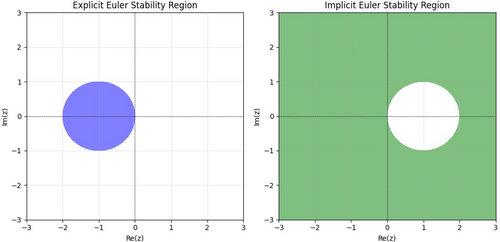
In contrast, the implicit Euler method has a stability region that covers almost the entire complex plane, excluding a small area near . This reflects its unconditional stability for most practical problems, even when large step sizes are used. Physically, this robustness allows implicit Euler to handle stiff systems effectively, where rapid changes or dynamics spanning multiple timescales are present. However, this method introduces numerical damping, which stabilizes the solution but can overly dampen oscillatory behavior, potentially reducing accuracy for non-stiff systems.
3.1.5 Implicit Midpoint Method
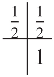
- Compute the slope using the current values of time and state [23]:
(13)where is the step size, is the current time, and is the current state.
- Update the state using the computed slope :
(14)
- Implicit evaluation of the slope: the slope is computed at the midpoint of the time interval, , using the current state and the derivative . This implicit evaluation of the slope is what distinguishes the implicit midpoint method from the explicit midpoint method.
- Improved stability: the implicit nature of the method provides improved stability compared with explicit methods, making it suitable for solving stiff differential equations.
The implicit midpoint method requires only a single starting value, which serves as the initial condition. However, it necessitates iterations to compute the solution at each step in this implementation and it requires evaluating function twice per step.
3.1.6 Modified Euler's (Heun's) or RK2 Method
3.1.7 Stability Region of Heun's Method
The stability of the modified Euler's method, analyzed via above equation. The stability function for the RK2 can be expressed as . Stability necessitates , indicating the region in the stability plane where defines the stability region for the RK2 method.
The modified Euler's or Heun's Method, combining the predictions from the predictor and corrector steps to improve the accuracy. It involves a two-step process: a predictor step and a corrector step.
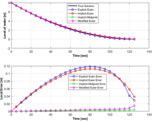
Figure 5 compares the outcomes of water tank drainage system for all Euler methods for a step size of . To highlight the differences among the methods, the local error is plotted, distinguishing the variations in the numerical solutions. As observed from the absolute error in Figure 5 and the summary of local errors in Table 2, which depicts the maximum errors of the four numerical methods applied to the water drainage system, it is evident that the implicit midpoint method outperforms the others with the lowest maximum error of 0.004103 m. This result underscores its superior accuracy in approximating the true solution. Conversely, both the explicit and implicit Euler's methods exhibit higher maximum local errors of 0.118394 and 0.112254 m, respectively, indicating reduced accuracy in their predictions. The modified Euler or RK2 method, as expected, yields better accuracy than both implicit and explicit Euler's methods (with a local error of 0.014896 m). When comparing implicit and explicit Euler's methods, implicit Euler's stability stands out, especially in handling stiff ODEs. A stiff ODE is a differential equation that requires an extremely small step size for certain numerical methods to be stable due to rapid variations in the solution [8, 27]. Implicit methods, similar to implicit Euler, are robust and offer accurate solutions for challenging differential equations, making them reliable for scenarios involving complex dynamics and stiff equations. Implicit methods, however, require more computations due to iterative processes, contrasting with the single iteration per step in explicit methods. While explicit Euler is computationally less intensive, modified Euler strikes a balance between accuracy and computational demand, making it popular for practical applications. Additionally, the choice of step size affects solution accuracy. A larger step size results in larger errors, while a smaller step size leads to smaller errors. This analysis is also discussed in the section on predictor-corrector methods in this article.
| Method | Global error [m] | Maximum local error [m] |
|---|---|---|
| Explicit Euler | 0.086143 | 0.118394 |
| Implicit Euler | 0.083054 | 0.112254 |
| Modified Euler (RK2) | 0.0048274 | 0.014896 |
| Implicit midpoint | 0.0019341 | 0.004103 |
3.2 Draining a Water Tank Using RK4 Methods
3.2.1 Stability Region of RK4 Method
The stability of this method is determined by analyzing the RK4 equation. To derive the stability region, a test function is substituted into the method and the function, for the RK4 method is obtained through back substitution into the above equation [8, 9, 11, 12]. For stability, it is essential that . Its stability region is the region where .
The absolute region of stability of the RK4 method is broader compared with that of the RK2 and Euler's methods, as illustrated Figure 6 and expands with the order of the RK method. Each shaded region corresponds to the stability region of a specific RK method, including explicit Euler, modified Euler or RK2, and RK4. These shaded areas visually represent where the numerical method maintains stability. The unshaded regions beyond these stability regions indicate areas where the numerical method may become unstable, leading to unbounded growth or oscillatory behavior in the solutions.

As shown in Figure 6, the stability regions: explicit Euler, modified Euler (or RK2), andRK4 provide insight into their behavior in solving ODEs. Each method has a specific stability function, which determines whether the numerical solution remains bounded for a given step size and problem dynamics. For explicit Euler, the stability region is a small circle centered at in the complex plane, indicating that stability is only achieved for eigenvalues of the system's dynamics matrix (scaled by the step size) that fall within this limited area. Physically, this implies that explicit Euler is conditionally stable and can only handle systems with slow dynamics or non-stiff behavior effectively, as larger step sizes or fast-changing dynamics would lead to instability.
In contrast, modified Euler (or RK2) and RK4 methods exhibit larger stability regions, providing greater flexibility and stability for a wider range of problems. The modified Euler (or RK2) method's stability region is larger than that of explicit Euler but still limited compared with RK4. The RK4 method has the largest stability region among the three, making it suitable for problems requiring higher precision and stability over larger step sizes. However, neither modified Euler (or RK2) nor RK4 can handle stiff problems effectively, as their stability regions remain bounded, unlike implicit methods.
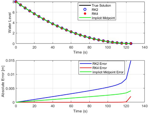
Figure 7 compares the outcomes of water tank drainage system for implicit midpoint Euler's method, modified Euler (or RK2) and RK4 for a step size of . To highlight the differences among the methods, the local error is plotted, distinguishing the variations in the numerical solutions. When evaluating the accuracy of each numerical method, as depicted in Figure 7 and summarized in Table 3, the RK4 method demonstrates superior performance with a local error of 0.002099m, outperforming the implicit midpoint Euler's method with a local error of 0.004103m. The results from the implicit midpoint Euler's method are notably better than those of the modified Euler's (RK2) method, which has a local error of 0.014896m. Hence, the RK4 method, known for its higher accuracy, excels in delivering enhanced performance. In numerical methods, particularly for solving differential equations, computational effort and percent relative error are key factors considered when comparing different solution methods. The computational effort is primarily determined by the number of function evaluations required to compute the solution over a given time interval. For Runge-Kutta (RK) methods, the computational effort is proportional to the order of the method, as higher-order methods generally require more function evaluations per step. In this context, the effort is calculated as the number of steps (dependent on the time step size) multiplied by the number of function evaluations per step. For RK2, two function evaluations per step are needed. In RK4, four function evaluations are required per step. The implicit midpoint method, a second-order method, also requires two function evaluations per step, similar to RK2. These computational efforts are used to estimate the run time or time taken to compute the solution, a critical consideration for practical applications.
| Method | Global error [m] | Maximum local error [m] |
|---|---|---|
| RK4 | 0.00041243 | 0.002099 |
| Implicit midpoint | 0.0019341 | 0.004103 |
| Modified Euler (RK2) | 0.0048274 | 0.014896 |
The percent relative error provides a measure of the accuracy of the numerical solution compared with the true solution (often derived analytically for comparison). It is computed as the average relative difference between the computed solution and the true solution, expressed as a percentage. A lower percent relative error indicates better accuracy of the numerical method.
3.3 Draining a Water Tank Using Explicit Adams–Bashforth Methods
| Order | cp | |||||
|---|---|---|---|---|---|---|
| 1 | 1 | 1 | ||||
| 2 | 3 | −1 | ||||
| 3 | 23 | −16 | 5 | |||
| 4 | 55 | −59 | 37 | −9 | ||
| 5 | 1901 | −2774 | 2616 | −1274 | 251 |
| Order | Adams-Bashforth Equation |
|---|---|
| 1 | |
| 2 | |
| 3 | |
| 4 | |
| 5 |
3.3.1 Euler's Method (Adams-Bashforth One-Step Method)
3.3.2 Adams-Bashforth Two-Step Method
On the other hand, the two-step Adams-Bashforth method requires two starting values, one of which serves as the initial condition of the dependent variable, while the other is typically obtained using a single-step method such as the explicit Euler method. For this specific implementation, it requires evaluating function twice per step for prediction purposes.
3.3.3 Adams-Bashforth Three-Step Method
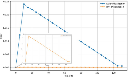
The accuracy of the three-step Adams-Bashforth method is highly dependent on the precision of the initial values used for the first three steps. In fact, the initial values for higher-order multi-step methods are typically computed using lower-order multi-step methods or alternative one-step methods. Given that these initial values are generally obtained using a one-step method, such as the explicit Euler or RK4 method, any errors introduced during this initialization phase can propagate and adversely impact the overall accuracy of the solution. Consequently, using a more accurate method, such as RK4, to compute the starting values is crucial for enhancing the reliability and precision of the Adams-Bashforth method. Specifically, in the case of the water drainage problem analyzed in this study, the RK4 method was utilized to determine the initial values.
The choice of initialization method, therefore, plays a significant role in determining the performance of the multi-step Adams-Bashforth method. While Euler initialization is faster and simpler, it introduces larger errors, which tend to accumulate over time. Conversely, RK4 initialization provides a higher degree of accuracy, effectively reducing errors and yielding a more stable and reliable solution, as illustrated in Figure 8. Thus, for problems where accuracy is critical, particularly over extended time periods, RK4 initialization emerges as the preferred approach. This method leads to more accurate approximations with fewer errors compared with Euler initialization, underscoring its importance in applications demanding high precision.
3.3.4 Adams-Bashforth Four-Step Method
The fourth-order method uses the current and three previous points , , , and . The coefficients are chosen to achieve a higher-order approximation and requires four function evaluations per step. The four-step Adams-Bashforth method requires four starting values. The first value serves as the initial condition of the dependent variable, while the additional three values are typically obtained using a one-step method, such as the explicit Euler or RK4 method, to initialize the process. This method involves evaluating the function four times per step for prediction. The accuracy of the four-step Adams-Bashforth method is heavily influenced by the precision of the initial values used for the first four steps. These initial values are typically computed using either a lower-order method (such as the three-step Adams-Bashforth) or a one-step method (such as the explicit Euler or RK4 method). However, any errors introduced during this initialization phase can propagate and significantly impact the overall accuracy of the solution. Therefore, using a more accurate method, such as RK4, to compute the starting values can greatly enhance the reliability and precision of the Adams-Bashforth method. In the context of the water drainage problem examined in this study, the RK4 method was utilized to calculate the initial values.
3.3.5 Adams-Bashforth Five-Step Method
This is the fifth-order method, which uses the current point and the four previous points , , , and . The coefficients are specifically chosen and requires five function evaluations per step. Similarly, the five-step Adams-Bashforth method requires five starting values. The first value serves as the initial condition of the dependent variable, while the additional four values are typically obtained using a one-step method, such as the explicit Euler or RK4 method, to initialize the process. This method also requires evaluating the function five times per step for prediction. The accuracy of the five-step Adams-Bashforth method depends on the accuracy of the initial values used for the first five steps. These initial values, computed using a one-step method, introduce errors that can propagate and impact the overall accuracy of the solution. Therefore, using a higher-order method such as RK4 to calculate the initial values can help improve the overall precision and reliability of the solution. For this study, the RK4 method was utilized to determine the initial values for the five-step Adams-Bashforth method. Theoretically, these methods are explicit and do not involve solving implicit equations, which typically makes them computationally less expensive.
3.3.6 Stability Region of Adams-Bashforth Explicit Methods
In the stability plots in Figure 9, the shaded regions represent the stable areas for each explicit Adams-Bashforth method, where the numerical solution remains bounded and converges. The unshaded areas outside these regions indicate potential instability, where the solution may diverge. As the order of the method increases, the stability region shrinks, meaning higher-order methods are less stable and may require smaller step sizes to maintain accuracy and avoid instability. This illustrates the trade-off between computational effort and stability when choosing an appropriate method for solving ODEs.
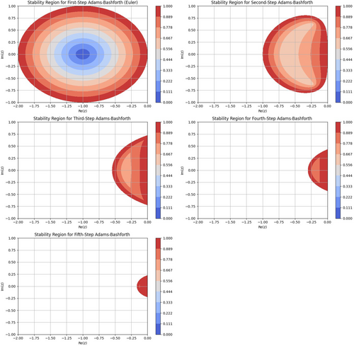
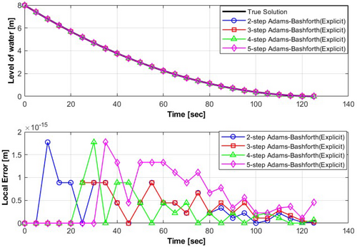
As shown in Figure 9, low-order methods (such as the first and second-step Adams-Bashforth methods) exhibit relatively larger stability regions, making them more tolerant of larger step sizes. In contrast, high-order methods (including the third, fourth, and fifth-step Adams-Bashforth methods) have smaller stability regions, necessitating smaller step sizes to maintain numerical stability. Figure 10 compares the outcomes of water tank drainage system for all steps of the explicit Adams-Bashforth method with a step size of . To highlight the differences among the methods, the local error is plotted, distinguishing the variations in the numerical solutions. As shown in Figure 10 and Table 6, the results from all steps of the explicit Adams-Bashforth methods show robustness compared with previous methods. Particularly, the 3rd-order explicit Adams-Bashforth method stands out with an absolute error of , offering the most accurate solution for this problem.
| Method | Global error [m] | Maximum local error [m] |
|---|---|---|
| Adams-Bashforth Two-Step Method | ||
| Adams-Bashforth Three-Step Method | ||
| Adams-Bashforth Four-Step Method | ||
| Adams-Bashforth Five-Step Method |
3.4 Draining a Water Tank Using Implicit Adams-Moulton Methods
| Order | cp | |||||
|---|---|---|---|---|---|---|
| 1 | 1 | 1 | ||||
| 2 | 1 | 1 | ||||
| 3 | 5 | 8 | −1 | |||
| 4 | 9 | 19 | −5 | 1 | ||
| 5 | 251 | 646 | −264 | 106 | −19 |
3.4.1 Adams-Moulton Implicit Method Stability
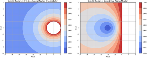
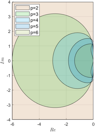
Adams-Moulton methods, being implicit, typically offer larger stability regions compared with explicit methods like Adams-Bashforth. Additionally, this expanded stability region allows Adams-Moulton methods to take larger time steps without losing stability, which can enhance computational efficiency for certain problems. However, their implicit nature requires solving nonlinear equations at each step, increasing memory consumption and computational effort. Furthermore, despite these additional computational costs, Adams-Moulton methods are particularly beneficial in scenarios where larger time steps are necessary to maintain efficiency without sacrificing stability.
The stability region comparison underscores the trade-offs between computational cost and stability as the method order increases. Multi-step methods offer enhanced stability within specific step size ranges (stability zones), which narrow with higher-order methods. Moreover, while implicit methods like Adams-Moulton provide superior stability, they demand greater computational resources, necessitating careful consideration of stability, memory usage, and computational effort, especially in complex systems requiring long simulations.
This discussion highlights the importance of selecting an appropriate numerical method based on the problem's stiffness, accuracy requirements, and available computational resources. Additionally, the balance between stability, accuracy, and computational intensity is crucial in ensuring the efficiency and reliability of numerical solutions in practical applications.
Figure 13 compares the outcomes of water tank drainage system for all implicit Adams-Moulton methods for a step size of . To highlight the differences among the methods, the local error is plotted, distinguishing the variations in the numerical solutions. As shown in Figure 13 and summarized in the Table 9, the results obtained from all steps of the implicit Adams-Moulton methods prove to be robust in solving the problem when compared with the previously discussed methods. In the context of this specific problem, the 3rd-order implicit Adams-Moulton Method stands out an absolute error of providing the most accurate results compared with the other methods.
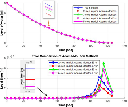
| Method | Global error [m] | Maximum local error [m] |
|---|---|---|
| Adams-Moulton Two-Step Method | ||
| Adams-Moulton Three-Step Method | ||
| Adams-Moulton Four-Step Method | ||
| Adams-Moulton Five-Step Method |
3.5 Draining a Water Tank Using Predictor-Corrector Methods
- i.
Predictor step: predicts the next value using the Adams-Bashforth method.
- ii.
Corrector step: refines the prediction using the Adams-Moulton method. This combination of methods leads to better accuracy in solving ODEs. In this article, the second and third-step Adams-Bashforth-Moulton method is presented for solving the water drainage problem.
- a.
Adams-Bashforth predictor (2nd order): Adams-Bashforth predictor (2nd order) method is given by the following equation:
(35) - b.
Adams-Moulton corrector (2nd order): Adams-Moulton corrector (2nd order) method is given by the following equation:
(36)
The results from this algorithm implementation is shown the Figure 14, the predictor-corrector method (2nd-order Adams-Bashforth-Moulton) yields satisfactory results for this specific problem.
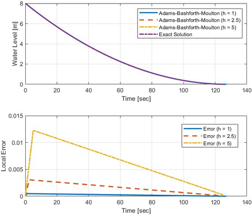
The 2nd-order Adams-Bashforth-Moulton method's numerical simulations with different step sizes offer insights into solving the water drainage problem as shown in Table 10.
| Step size () | Global error [m] | Maximum local error [m] |
|---|---|---|
| 1 | 0.00028343 | 0.000490 |
| 2.5 | 0.0017803 | 0.003066 |
| 5 | 0.0070897 | 0.012263 |
For , the global error is with a local error of , while for , the global error increases to with a maximum local error of , highlighting the importance of smaller step sizes for accuracy. With , the global error rises to with a local error of , underscoring the need for careful selection of step size for accurate numerical solutions, balancing between accuracy and computational cost.
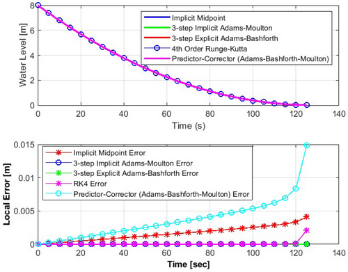
The step size should be small enough to ensure accuracy, minimize truncation error, and guarantee the convergence of the solution between successive iterations. Conversely, the step size should be large enough to reduce runtime costs and minimize the accumulation of round-off errors. Balancing these opposing requirements involves a trade-off between accuracy and computational efficiency. Lastly, this section compares the performance of selected numerical methods, including the implicit midpoint method, the fourth-order Runge–Kutta method (RK4), the third-order implicit Adams-Moulton method, the explicit Adams-Bashforth method, and the Adams-Bashforth-Moulton method, in solving the water drainage system problem. According to Figure 15, comparing the implicit midpoint, RK4, third-order implicit and explicit, and Adams-Bashforth-Moulton methods, it is clear that the third-order implicit and explicit Adams-Moulton methods outperform the others, showing nearly zero absolute errors, indicating exceptional accuracy. Multi-step methods offer computational efficiency advantages over one-step methods but require knowledge of the solution at multiple points for initialization.
4 Discussions
4.1 Comparison of Various One-Step Methods
As discussed in the numerical analysis and results section, various one-step methods—including explicit (forward), implicit (backward), implicit midpoint, modified Euler's, and the fourth-order Runge–Kutta methods—were evaluated for the water drainage system.
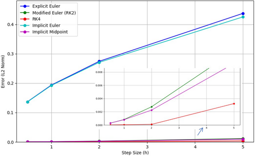
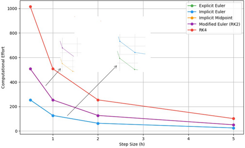
Figure 16 shows the relationship between the step size and the error (measured using the -norm) for the different numerical methods. As expected, smaller step sizes generally result in reduced error for all methods. The higher-order methods, such as the RK4, exhibit superior accuracy at larger step sizes compared with lower-order methods like the explicit Euler. Notably, the error for RK4 decreases more rapidly with smaller , reflecting its higher-order accuracy. In contrast, the explicit Euler and implicit Euler methods show higher errors at all step sizes, highlighting the limitations of first-order accuracy in capturing the dynamics of the water drainage system. Figure 17 illustrates the trade-off between computational effort, defined as the number of function evaluations, and numerical error, plotting the error against the effort for various one-step numerical methods applied to the water drainage problem. Higher-order methods, such as RK4, deliver significantly lower errors for a given computational effort compared with lower-order methods like explicit Euler. Notably, RK4 exhibits a steep reduction in error at initial effort levels, but the improvement rate diminishes as computational effort increases. In contrast, explicit Euler shows only modest error reductions despite higher effort, underscoring its inefficiency for problems requiring high precision. As the step size decreases (see Table 11), the computational effort increases across all methods due to the greater number of time steps needed to span the simulation interval. While RK4 achieves superior accuracy, it incurs higher computational costs because of its four intermediate evaluations per time step. Methods such as explicit Euler and implicit Euler are computationally less demanding but sacrifice accuracy, making them less suitable for applications that prioritize precision. Figure 18 demonstrates the relationship between computational effort and step size () for one-step methods in the water drainage problem. As increases, the computational effort decreases across all methods due to fewer time steps, but this comes at the cost of accuracy (also see Table 11 for ). Explicit Euler, being the simplest, has the lowest computational effort, while RK4, with four function evaluations per step, is the most computationally intensive. Modified Euler (RK2) and implicit midpoint require intermediate effort, balancing accuracy and cost. Implicit Euler shows slightly higher effort than explicit Euler due to iterative calculations but maintains stability for larger . These trends highlight the trade-offs between effort and accuracy, guiding method selection based on problem requirements. In summary, the results highlight the trade-offs between accuracy, computational effort, and step size for numerical methods. Higher-order methods, particularly RK4, offer significant accuracy advantages for the water drainage system but at the cost of increased computational effort. The choice of method depends on the specific requirements of accuracy and computational efficiency for the given problem.
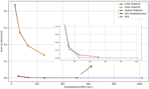
| Method | Step size (h) | Computational effort | Error (-norm) |
|---|---|---|---|
| Explicit Euler | 0.5 | 254.0 | 0.136461 |
| Implicit Euler | 0.5 | 254.0 | 0.136008 |
| Implicit Midpoint | 0.5 | 508.0 | 0.000281 |
| Modified Euler (or RK2) | 0.5 | 508.0 | 0.000285 |
| RK4 | 0.5 | 1016.0 | 0.000002 |
| 3rd-Order Adams-Bashforth | 0.5 | 254.0 | 0.001132 |
| 3rd-Order Adams-Moulton | 0.5 | 2540.0 | 0.001133 |
| 3rd-Order Predictor-Corrector | 0.5 | 2805.0 | 0.001133 |
| Explicit Euler | 1.0 | 127.0 | 0.193295 |
| Implicit Euler | 1.0 | 127.0 | 0.192023 |
| Implicit Midpoint | 1.0 | 254.0 | 0.000798 |
| Modified Euler (or RK2) | 1.0 | 254.0 | 0.000821 |
| RK4 | 1.0 | 508.0 | 0.000030 |
| 3rd-Order Adams-Bashforth | 1.0 | 127.0 | 0.003204 |
| 3rd-Order Adams-Moulton | 1.0 | 1270.0 | 0.003207 |
| 3rd-Order Predictor-Corrector | 1.0 | 1408.0 | 0.003207 |
| Explicit Euler | 2.0 | 63.5 | 0.274230 |
| Implicit Euler | 2.0 | 63.5 | 0.270666 |
| Implicit Midpoint | 2.0 | 127.0 | 0.002244 |
| Modified Euler (or RK2) | 2.0 | 127.0 | 0.002749 |
| RK4 | 2.0 | 254.0 | 0.000086 |
| 3rd-Order Adams-Bashforth | 2.0 | 63.5 | 0.009074 |
| 3rd-Order Adams-Moulton | 2.0 | 630.0 | 0.009088 |
| 3rd-Order Predictor-Corrector | 2.0 | 715.0 | 0.009088 |
| Explicit Euler | 5.0 | 25.4 | 0.437324 |
| Implicit Euler | 5.0 | 25.4 | 0.425342 |
| Implicit Midpoint | 5.0 | 50.8 | 0.009284 |
| Modified Euler (or RK2) | 5.0 | 50.8 | 0.011118 |
| RK4 | 5.0 | 101.6 | 0.003228 |
| 3rd-Order Adams-Bashforth | 5.0 | 27.0 | 0.035981 |
| 3rd-Order Adams-Moulton | 5.0 | 270.0 | 0.036245 |
| 3rd-Order Predictor-Corrector | 5.0 | 297.0 | 0.036245 |
4.2 Comparison of Various Multi-Step Methods
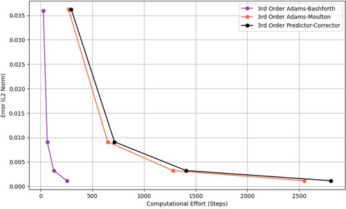
Additionally, in the numerical analysis and results section, various multi-step methods including the Adams-Bashforth (explicit), Adams-Moulton (implicit), and predictor-corrector (Adams-Bashforth-Moulton) methods were evaluated for the water drainage system. Figure 19 shows the error versus computational effort for the selected 3-step Adams-Bashforth (explicit), Adams-Moulton (implicit), and Predictor-Corrector (Adams-Bashforth-Moulton) methods with a fixed step size of . The explicit 3-step Adams-Bashforth method, while offering lower computational effort, exhibits higher error levels compared with the implicit methods. In contrast, the implicit 3-step Adams-Moulton method provides better accuracy with increased computational effort, owing to its stable nature. The Predictor-Corrector method, which combines both Adams-Bashforth and Adams-Moulton methods, shows similar accuracy to the Adams-Moulton method but with a slightly higher computational cost (also see Table 11).
4.3 Comparison of Various One-Step Methods With Various Multi-Step Numerical Methods
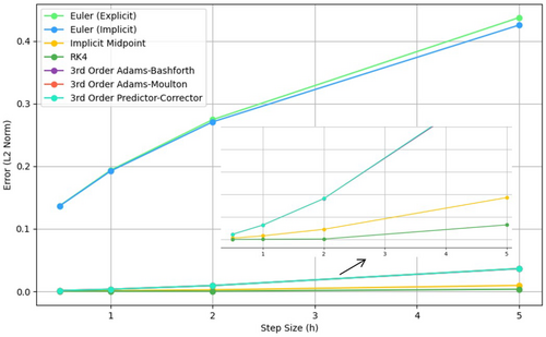
Moreover, in the numerical analysis and results section, various multi-step methods—including the Adams-Bashforth (explicit), Adams-Moulton (implicit), and predictor-corrector (Adams-Bashforth-Moulton) methods—were evaluated for the water drainage system. The results of the comparison between the numerical methods (RK4, implicit midpoint, 3-Step Adams-Bashforth, 3-step Adams-Moulton, and 3rd-order predictor-corrector) are analyzed through three primary plots: error versus step size, error versus computational effort, and error versus time.
4.3.1 Error Versus Step Size
Figure 20 demonstrates the relationship between the error and the step size for each method. As the step size decreases, a reduction in the error is observed for most methods. Smaller step sizes result in more accurate approximations. The RK4 method exhibits a steady decrease in error with smaller step sizes, due to its higher order of accuracy. The implicit midpoint method, though stable for larger step sizes, shows a slower reduction in error compared with RK4, as implicit methods tend to be more stable but less efficient in reducing error. The 3-Step Adams-Bashforth method, being explicit, demonstrates a more significant decrease in error as the step size decreases, though the accuracy remains lower than RK4. Similarly, the 3-Step Adams-Moulton method, which is implicit, shows a comparable reduction in error, but it may perform slightly better than Adams-Bashforth, due to the correction factor. The 3rd-order predictor-corrector method combines both the Adams-Bashforth predictor and Adams-Moulton corrector, resulting in a more consistent and rapid reduction in error compared with the Adams methods, making it highly efficient for smaller step sizes.
4.3.2 Error Versus Computational Effort
Figure 21 compares the error with the computational effort, measured as the number of steps, for selected one-step and multi-step numerical methods applied to the water drainage problem with a fixed step size of . For one-step methods, the explicit Euler and implicit Euler methods both require 127 computational units, with the explicit Euler method yielding a higher error of 0.193295 compared with the implicit Euler method's error of 0.192023. The implicit midpoint method, on the other hand, requires 254 units and delivers a much lower error of 0.000798. Among the multi-step methods, the 3rd-order Adams-Bashforth method requires 127 units, yielding an error of 0.003204, whereas the 3rd-order Adams-Moulton method needs 1270 units with an error of 0.003207. The 3rd-order predictor-corrector method demands 1408 units, producing an error of 0.003207. Thus, although the one-step methods such as the explicit and implicit Euler methods require fewer computational steps (127 units), they exhibit higher errors compared with the multi-step methods. The multi-step methods, though computationally more expensive, generally yield much lower errors, with the 3rd-order Adams-Moulton and predictor-corrector methods delivering comparable results at higher computational costs.
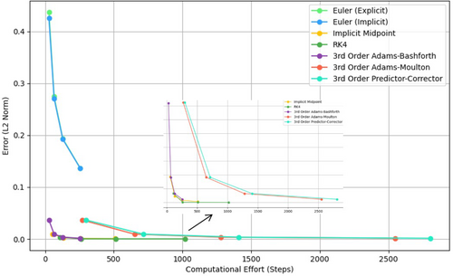
Table 11 presents a comparison of various selected one-step and multi-step numerical methods applied to the water drainage problem, with different step sizes (), computational effort, and associated errors. The step size () plays a crucial role in determining the computational effort required for each method. As expected, larger step sizes, such as , generally result in a lower computational effort. For example, Euler (explicit) and Euler (implicit) methods require only 25.4 computational units at , compared with 254 units at . However, this decrease in computational effort comes at the expense of accuracy, as seen in the increased -norm error at larger step sizes. The Euler methods exhibit much larger errors at higher step sizes, with the error for Euler (Explicit) increasing from 0.136461 at to 0.437324 at . This shows that larger step sizes compromise the accuracy of the solution.
On the other hand, the -norm error generally increases with larger step sizes, a characteristic common to most numerical methods. For smaller step sizes, methods such as RK4, implicit midpoint, and 3rd-order Adams-Bashforth maintain relatively low errors. For instance, RK4 shows excellent accuracy with an error of 0.000002 at , and still performs well at and , with errors of 0.000030 and 0.000086, respectively. This demonstrates that RK4 is highly accurate, even at larger step sizes, while methods such as Euler (explicit) and Euler (implicit) show a substantial increase in error as the step size grows.
In terms of method performance, RK4 stands out for its consistent accuracy across various step sizes. Although RK4 requires moderate computational effort (1016 at and 508 at ), it provides remarkably low errors, making it an excellent choice for problems where accuracy is critical. The 3rd-order Adams-Bashforth, 3rd-order Adams-Moulton, and 3rd-order predictor-corrector methods, while offering good accuracy (with errors between 0.001132 and 0.001133 at ), require significantly higher computational effort, especially the 3rd-order Adams-Moulton method, which has a computational effort of 2540 at , and 270 at . These methods perform similarly to RK4 in terms of accuracy, but their computational cost is higher.
High-order methods such as the 3rd-order Adams-Bashforth, 3rd-order Adams-Moulton, and 3rd-order predictor-corrector provide a better balance between accuracy and computational effort at smaller step sizes. However, as the step size increases, the computational effort of these methods rises steeply, while their error remains relatively consistent. For instance, at , the computational effort for the 3rd-order Adams-Moulton method is 270, and the error remains around 0.036245, similar to the error at .
4.4 Benefits and Limitations of Each Numerical Scheme Method
One-step methods, such as Euler's method and Runge-Kutta methods, are straightforward to implement and require minimal memory since they do not store previous values. However, their simplicity comes at the cost of lower accuracy compared with multi-step methods when using the same step size. Additionally, one-step methods may face stability challenges, especially for stiff equations, necessitating very small step sizes.
In contrast, multi-step methods, such as Adams-Bashforth and Adams-Moulton, use information from previous steps, making them more efficient and accurate for the same computational effort. They allow for larger step sizes and achieve higher accuracy with fewer function evaluations. However, these methods are more complex to implement, requiring storage of multiple past values, special starting procedures, and higher memory usage.
Implicit methods offer notable advantages in stability and accuracy, particularly for stiff equations, making them suitable for a wide range of problems. However, they involve solving nonlinear equations at each step, which increases computational complexity and time. Implementing implicit methods also requires advanced techniques for solving implicit equations.
Explicit methods, on the other hand, are simpler to implement and faster per step, making them appealing for problems where stiffness is not a concern. However, they are generally less stable and accurate for certain equations, especially when large step sizes are used, requiring careful consideration to ensure reliable results.
4.5 Stability Considerations
Stability is a critical property of numerical methods, particularly when solving differential equations. It refers to the method's ability to control the growth of errors introduced during computations. A stable method ensures that errors, whether due to initial conditions, rounding, or truncation, do not grow uncontrollably as computations proceed. For numerical methods, stability is analyzed in the context of a test problem, such as the linear ODE , where is a complex constant. The behavior of the numerical solution depends on the step size and the method used.
Explicit methods, such as Adams-Bashforth methods, are efficient but have limited stability regions and are conditionally stable, requiring smaller step sizes to maintain stability. These methods are not ideal for stiff equations, where larger step sizes are necessary, as they may become unstable under such conditions. Implicit methods, including backward Euler and Adams-Moulton methods, are more suited for stiff problems due to their larger or even unbounded stability regions. This ensures stability regardless of the step size, making them effective for challenging numerical problems. However, their stability advantage comes at the cost of increased computational effort, as solving additional equations is required at each step.
Multi-step methods, like the Adams-Bashforth and Adams-Moulton families, strike a balance between computational efficiency and stability. While higher-order methods offer improved accuracy, they often involve more complex stability considerations. Explicit multi-step methods experience shrinking stability regions as the order increases, whereas implicit methods maintain broader stability, making them suitable for a wider range of problems.
4.6 Practical Application in Water Tank Drainage and Recommendations
If computational resources are a limiting factor, one-step numerical methods, such as implicit Euler, RK2, and implicit midpoint, offer relatively low computational costs while still providing reasonable accuracy. For problems that require higher precision but without the computational overhead of solving implicit equations, RK4 can be the optimal choice, especially when computational resources are not heavily constrained. For more complex systems or stiff problems, multi-step methods such as implicit Adams-Moulton or predictor-corrector methods may be necessary due to their superior stability properties, although they come with higher computational costs. The multi-step Adams-Bashforth method, being explicit, is useful when an explicit method is preferred, but its higher error levels (compared with implicit or RK methods) may make it less favorable for problems requiring high accuracy.
The findings from this study can be applied in real-world water management systems to optimize the design of drainage systems, prevent overflow, and improve emergency response strategies. By accurately modeling water drainage dynamics, the study aids in designing efficient systems that prevent stagnation or overflow while ensuring effective water flow. It also supports the development of predictive control systems for real-time monitoring, helping to avoid overflow scenarios. Additionally, the insights on computational effort and accuracy guide the selection of numerical methods for smart water management systems, ensuring both efficiency and precision in resource-constrained environments. Ultimately, these findings contribute to enhancing the reliability, efficiency, and resilience of water management infrastructures.
5 Conclusions
This article presents a comparative analysis of various numerical methods applied to solve the water drainage problem, focusing on their accuracy, stability, and computational efficiency. The comparison of one-step and multi-step methods reveals key insights into their strengths and limitations, highlighting their suitability for different problem types. The analysis shows that explicit methods, such as Euler's method, are computationally efficient but lose accuracy, especially with larger step sizes. In contrast, implicit methods, such as backward Euler and Adams-Moulton, offer broader stability regions, making them better suited for problems that require high stability, such as stiff equations or long-term simulations. While the RK4 method provides high accuracy for smaller step sizes, it incurs moderate computational costs. On the other hand, multi-step methods, like Adams and Predictor-Corrector, strike a balance between accuracy and efficiency, though they become more computationally intensive as the step size decreases. The study also emphasizes the trade-offs between accuracy, computational effort, and step size.
The selection of a numerical method should therefore be driven by the system's characteristics, computational resources, and the desired accuracy. For simpler systems or scenarios where computational efficiency is prioritized, one-step methods like Euler's method are ideal due to their lower computational cost. However, for problems that require greater accuracy, stability, and reliability, particularly for stiff systems or long-term simulations, multi-step methods are more appropriate. In these cases, implicit methods, such as backward Euler or Adams-Moulton, are particularly effective because of their larger stability regions.
When choosing between one-step and multi-step methods, it is crucial to consider the problem's complexity. One-step methods, such as Euler or RK4, are well-suited for simpler problems or when rapid computations are necessary, where accuracy may not be as critical. These methods are beneficial for small-scale problems where computational efficiency is a priority. Conversely, multi-step methods such as Adams-Bashforth, Adams-Moulton, and Predictor-Corrector should be used for more complex problems that demand higher accuracy and stability. Although they are computationally more expensive, these methods provide superior accuracy for smaller step sizes and are recommended when more robust solutions are required.
In summary, the study underscores the importance of selecting the appropriate numerical method based on the specific demands of the problem.
Key findings of this study in terms of accuracy, computational efficiency, and stability are as follows:
Accuracy: multi-step methods, particularly Adams-Bashforth, demonstrated higher accuracy than one-step methods (e.g., explicit Euler and RK4), especially in long-term simulations where they more effectively capture the dynamics of the water tank drainage system. However, the accuracy of these methods depends on the initial values, with higher-order methods such as RK4 providing more accurate starting points and thus enhancing the overall accuracy. Computational efficiency: one-step methods generally require fewer function evaluations per time step compared with multi-step methods. The explicit Euler method, for example, is the least computationally expensive, but its lower accuracy may necessitate smaller time steps for precision. Multi-step methods, while computationally more intensive, achieve higher accuracy for the same step size. Consequently, multi-step methods offer a better balance of accuracy and efficiency for longer simulations.
Stability: stability analysis revealed that one-step methods, particularly explicit Euler, are less stable with large step sizes, leading to potential numerical instability. In contrast, multi-step methods, such as Adams-Bashforth, showed improved stability, especially when initialized with a higher-order method such as RK4. This enhanced stability is essential for preventing divergence in long-term simulations. Future work will explore the integration of fractional-order differential equations, particularly for modeling systems with memory effects, such as water drainage. Additionally, the methods studied here will be applied to a broader range of real-world problems, including fluid dynamics, chemical reactions, and environmental simulations, to assess their general applicability and performance. These efforts aim to improve modeling accuracy, computational efficiency, and expand the use of numerical methods in solving complex engineering and scientific challenges.
Author Contributions
Abebe Alemu Wendimu: conceptualization; methodology; data curation; writing – original draft; writing – review and editing; visualization; validation. Radek Matušů: supervision. František Gazdoš: supervision. Ibrahim Shaikh: writing – review and editing.
Acknowledgements
This work was supported by the Internal Grant Agency of the Tomas Bata University in Zlín, under the project number IGA/CebiaTech/2024/001.
Ethics Statement
Review or approval by an ethics committee was not needed for this study because no data on human, human clinical studies, vertibrates or higher invertebrates or experimental animals was used in the article. Informed consent was not required for this study because no clinical data was produced in the review article.
Conflicts of Interest
The authors declare no conflicts of interest.
Appendix A
The full MATLAB code implementation used in this article is available on GitHub: MATLAB implementation.
Open Research
Data Availability Statement
The datasets supporting the conclusions of this study are included within the article. For further investigation, data will be made available upon request.


