Numerical Investigation Into Effect of Canyon Terrain Boundaries on the Seismic Response of Deep-Water Bridge Piers
ABSTRACT
Bridge piers in deep reservoirs with canyon terrain boundaries are subject to complex hydrodynamic effects during earthquakes. In this study, a framework with added mass is adopted to calculate the effects of canyon terrain boundaries. This approach is demonstrated to be effective and accurate after the results from the fluid–structure interaction model and the model with the added mass method are compared. Then, the impacts of canyon terrain boundaries on the seismic response of bridge piers in deep reservoirs are numerically investigated. The effects of key parameters such as the pier-to-boundary distance, terrain slope angle, and water depth are also thoroughly studied. The results indicate that the canyon tunnel boundaries have larger influence zones along the height of the bridge pier when it has a larger terrain slope angle and a lower water depth. Although the dynamic characteristics did not change much after the specific topographic conditions were considered, the dynamic response greatly increased in terms of base forces and deformation. Moreover, this study underscores the critical importance of canyon terrain boundary conditions in the seismic design of bridges in mountainous reservoir regions.
1 Introduction
In recent years, the rapid development of hydroelectric infrastructure in western China has led to the widespread construction of reservoirs in deep valley regions. To accommodate such complex topographies, many high-pier bridges have been constructed, many of which are expected to be partially or fully submerged once the reservoirs are filled [1]. In moderate and high seismic zones, the hydrodynamic effect has become a critical factor for the seismic design of bridges in aquatic environments [2-4]. The interaction between the vibrating structures and the surrounding water will alter the structural vibration period and amplify structural seismic responses. This phenomenon might significantly increase the risk of structural failure with the excitation of earthquakes [5-7].
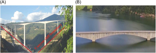
To evaluate the effect of deep water on the structural dynamic response triggered by earthquakes, Westergaard [8] proposed the added mass method and analyzed the dynamic response of a dam. Because of its simplicity and practicality, this approach has been accepted for bridge specifications [3, 9, 10]. Many studies have been conducted to calculate the added mass on structures analytically and numerically. For example, Goyal and Chopra [11] utilized a discrete analytical approach to calculate the added mass of towers with different cross-sectional shapes, such as elliptical, rectangular, and rounded-end cylinders. Yang and Li [12] developed a fitting formula for added mass on the basis of the fundamental frequency reduction rates, and then, the hydrodynamic pressure on piers with arbitrary cross-section shapes was calculated. Zhang et al. [13] proposed a numerical model to evaluate the added mass of immersed columns for any section type. These existing methods assume that the water domain around the bridge pier is symmetric [14, 15] and infinite [3, 13, 16, 17]. This condition is common and accurate for coastal bridges. However, the fluid conditions are quite different when a bridge crosses a reservoir with a canyon terrain boundary, such as the Mangjiedu Bridge in Southwest China [18, 19] shown in Figure 1. This typical topographic condition results in an asymmetric water domain around the pier. The assumption with an infinite water domain cannot demonstrate practical states. As a result, this may lead to the underestimation of the hydrodynamic effect for deep-water bridges. Considering the influence of adjacent boundaries, Liu et al. [20] studied boundary effects on the seismic response of concrete bridge piers. Since limited water domains can increase the reflection of compression waves acting on underwater structures, the reduced distance between the pier and rigid vertical boundary can increase the hydrodynamic forces on the bridge pier. This phenomenon is stressed by shaking table tests [21, 22]. Millán et al. [23] reported that the presence of an adjacent dam induces additional resonance modes and increases the seismic response of the tower by 20%. A similar study [24] indicated that dam proximity can significantly amplify the dynamic responses of the intake tower under horizontal and vertical excitations. However, investigations of the hydrodynamic effects of asymmetric water domains caused by canyon topography remain relatively limited.
This study investigated the effects of canyon terrain boundaries on the dynamic response of bridge structures. The added mass calculation framework with potential-based fluid–structure interaction models was adopted to derive the hydrodynamic effects of the water domain with canyon terrain boundaries. The accuracy of this method was validated by comparing the dynamic responses from both fluid–structure interaction models and the method with the lumped added mass. The distributions of added masses with different critical parameters of topographical boundary conditions, such as canyon proximity, slope angle, and submerged water depth, are investigated. Finally, the dynamic response of a bridge pier considering both the vertical cliff terrain boundary and the infinite water boundary conditions is studied.
2 Governing Equations of Fluid–Structure Interaction
The boundary and potential interface conditions are defined in the numerical model as:
- (1)
At the pier‒water interface, the potential fluid motion corresponds to the velocity of the structure. n indicates the unit vector normal to the fluid–structure interface:
() - (2)
At the water surface, where , the fluid potential is as follows:
() - (3)
At the far fluid boundary where no cliff boundary exists, the Sommerfeld boundary condition is applied to minimize the influence of secondary reflected waves:
() - (4)
At the canyon cliff boundary, a slipping rigid wall boundary condition is applied to represent the rigid contact behavior associated with underwater compressive wave propagation:
() - (5)
Under the assumption of potential fluid elements, the fluid is allowed to move freely along the tangential direction of the rigid wall boundary without energy dissipation. As water is nonviscous, there is no tangent force acting on such an interface:
()Under ground excitation, the dynamic response of the coupled fluid‒structure system, which is composed of the fluid velocity potential and normal velocity at the structure‒fluid interface, can be expressed as:
()()where and are vectors of the nodal displacement and nodal velocity potential vector, respectively; and represent the mass and stiffness matrices for the structure; and represent the mass and stiffness matrices for the fluid domain; and represent the compatible equilibriums for the fluid‒structure interaction at the interface; represents the damping matrix of the structure defined by the Rayleigh damping coefficients and ; represents the ground‒motion acceleration corresponding to the time history; and represent the matrices of the standard isoparametric shape function for the solid and fluid domains, respectively; and represent the densities of the structure and fluid, respectively; and represents the elasticity matrix for the structure domain. represents the surface of the structure‒fluid interaction, and represents the number of nodes for each fluid element.
3 The Added Mass Calculation Framework
3.1 Methodology
3.2 Numerical Model of a Bridge Pier With Canyon Terrain Boundaries
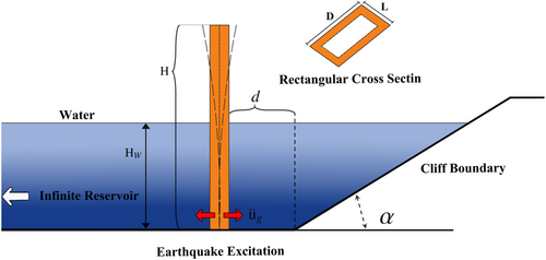
As shown in Figure 3, a hollow rectangular bridge pier submerged in a reservoir with a typical canyon terrain boundary condition is selected as an example. In this figure, D and L are the depth and width of the bridge pier, respectively, and H and Hw represent the pier height and water depth, respectively. For the canyon terrain boundary, d is the horizontal distance between the bridge pier surface and the base of the adjacent cliff boundary, and α refers to the slope angle characterizing the topography of the canyon terrain. The cliff boundary is assumed to have a smooth surface that is free of localized rock texture. The pier-water system vibrates together under ground excitation , whereas the cliff boundary is assumed to remain stationary during the earthquake in this study because of the large mass and high inertia of the valley cliff. This study initially models a bridge pier with a 12 × 8 m hollow rectangular cross-section and a wall thickness of 2 m, which is situated adjacent to a vertical canyon terrain boundary.
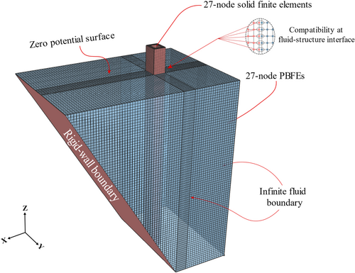
A three-dimensional fluid‒structure interaction model of bridge piers in deep water, considering canyon terrain boundaries was built with the ADINA [26, 27] program. As illustrated in Figure 4, the bridge pier is modeled with 27-node 3D solid elements, and the water domain is discretized into a collection of 27-node potential-based fluid elements (PBFEs). The rock-based reservoir bed is assumed to be smooth and is modeled with rigid wall boundary conditions; the interface between the structure and the water is simulated by a node‒node fluid‒structure coupling interface. Since the viscosity of water flow is limited for linear analysis, the canyon boundary is idealized as a slip wall boundary. The infinite region is used to model the condition without canyon terrain boundaries, where the distance to the structure is expected to be greater than eight times the sectional dimension. The effects of gravity-induced free-surface waves and hydrodynamic damping are omitted in this study because of their limited impact on the hydrodynamic response of deep-water bridge piers [7, 28].
3.3 Derivation of the Added Mass
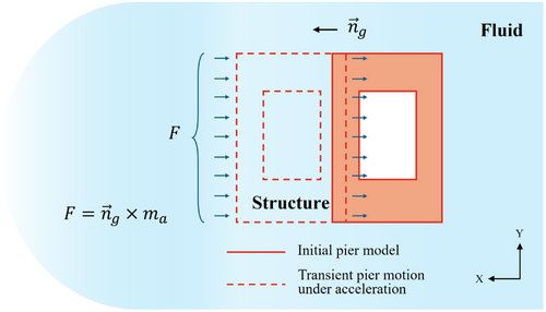
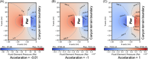
Following the framework described in Section 3.1, the added masses are calculated by applying acceleration loads of −0.01, −1, and 1 m/s2 in the X direction. The negative acceleration value indicates transient motion away from the canyon boundary, whereas a positive value represents compression of the confined water region as the structure moves toward the canyon boundary. Figure 5 presents the hydrodynamic pressure contours around the pier section at mid-height under three acceleration conditions. Notably, the contour value distribution of the hydrodynamic pressure in Figure 5A is exactly 0.01 times greater than that in Figure 5B, which directly corresponds to the scaling factor of the input acceleration. In Figure 5B,C the absolute values of the pressure field on both sides of the bridge pier remain identical. However, the direction of the pressure field is reversed. The results indicate a linear relationship between the input acceleration and the resulting pressure field, as well as the corresponding hydrodynamic force F. Therefore, in the linear potential-based numerical calculation for added mass with the presence of a canyon boundary, the final added mass remains at a fixed value, as it is independent of the transient motion of the structure. Another key finding from Figure 5 is that the hydrodynamic pressure field has an asymmetric distribution on both sides of the pier, with notable amplification on the side closer to the canyon terrain boundary. This amplification phenomenon is associated with compressive wave reflections from the canyon–terrian boundary.
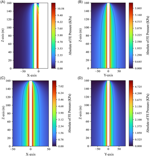
To further investigate the variation in the distribution of hydrodynamic forces under the same boundary conditions, Figure 6A,B present the hydrodynamic pressure contour distributions along the height of the bridge pier under acceleration loads with magnitudes of −1 in the X and Y directions. Figure 6C,D present reference cases with an infinite water domain condition for comparison. The contour plot clearly demonstrates that the presence of a nearby vertical cliff boundary can significantly amplify seismic hydrodynamic loading at the global level for piers in both the X and Y directions, corresponding to the parallel and perpendicular components relative to the confined boundary. These findings highlight the critical influence of specific rigid boundary conditions on fluid‒structure interactions, underscoring the need for careful consideration during hydrodynamic analysis.
3.4 Effect of Canyon Boundaries on the Added Mass
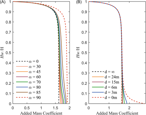
This section investigates the added mass under different canyon terrain boundary parameters. Figure 7A shows the variation in the added mass coefficient along the submerged depth (Hw = 160 m) of the same bridge pier perpendicular to the canyon boundary as a function of different pier–terrain distances d with the terrain slope angle fixed at 60°. Figure 7B shows the variation as a function of different terrain slope angles while maintaining a constant pier-to-terrain distance . Both cases highlight the spatial confinement effect of the rigid canyon boundary on the surrounding fluid domain around the pier. Compared with the infinite water domain condition, the added mass coefficient—defined as the ratio of added mass to displaced water mass—is significantly greater when the pier-to-boundary distance d is less than 15 m. Figure 7A illustrates the localized effects of varying canyon boundary conditions, with the influence region occurring primarily below a water depth ratio of 0.4. In Figure 7B, variations in the terrain slope angle exert a more global effect on the added mass distribution. When the canyon slope angle exceeds 60°, a noticeable deviation in the added mass coefficient curves is observed in the upper half of the pier. This finding indicates that the boundary-induced confinement effect not only amplifies hydrodynamic responses near the pier base but also extends its influence to the upper regions of the structure. When the terrain slope angle reaches 90°, the increase in the added mass coefficient becomes uniform throughout the entire pier height. Although near-vertical canyon slopes are uncommon in existing reservoir bridges, the growing number of deep-water bridges introduces similar challenges associated with confined water conditions, particularly during cofferdam or caisson construction in high-seismic-intensity regions.
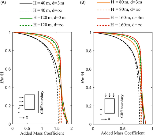
Owing to seasonal variations in water depth within reservoir areas, this study examines the influence of specific adjacent terrain boundary conditions (, ) on the added mass coefficient under different submerged water depth scenarios. Figure 8A,B illustrate the enhancement of the added mass distribution due to the canyon boundary effect across all water depths. This amplification is evident not only perpendicular to but also parallel to the canyon boundary. The influence is more pronounced in the X direction, corresponding to a greater shift in the curves. Additionally, the influence region from the canyon boundary shifts upward along the water depth ratio as the water depth decreases from 160 m to 40 m. This observation suggests that taller bridge piers with greater submerged depths are less sensitive to adjacent inclined boundary conditions. This reduction in sensitivity is attributed to the filling effect of wider upper canyon reservoir boundaries.
4 Dynamic Response of Bridge Piers With Canyon Terrain Boundaries
4.1 Modal Analysis
In deep canyon reservoir areas, bridge piers are typically tall and relatively flexible [29]. The rigid canyon boundary can significantly alter the magnitude of the added mass and its distribution pattern along the height of bridge piers. Therefore, the dynamic modal properties of a submerged bridge pier will change. To quantify this effect, modal analyses based on the FSI model and the added mass method are performed. As shown in Figure 9, the structure in the FSI model has solid elements and is directly coupled with potential-based fluid elements. Both the infinite boundary condition and canyon terrain boundary states are investigated. Notably, two extreme canyon topographic configurations with terrain slope angles of 0° and 90° (as illustrated in Figure 9) were selected to highlight the structural dynamic differences induced by terrain boundary effects. All these cases are also modeled with the added mass method on the platform of OpenSees [30]. As shown in Figure 9C, the added masses are incorporated in both the X direction and the Y direction. Both configurations feature the same submerged water depth of 160 m and pier-to-boundary distance of 6 m, providing a consistent basis for comparison. The structure was modeled as an elastic material with an elastic modulus of 40 GPa, a Poisson's ratio of 0.2, and a density of 2500 kg/m3. A concentrated mass of 300 tons was applied at the top of the pier in both numerical models to simulate the effect of the superstructure.
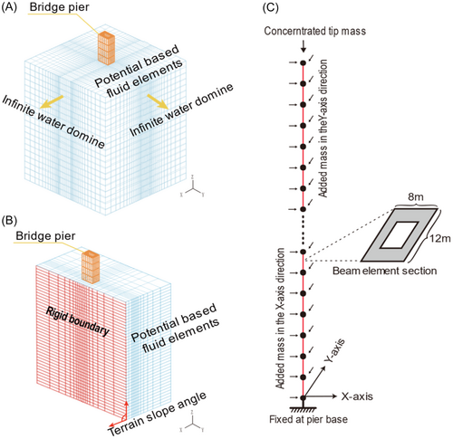
To evaluate the impact of the adjacent terrain boundary on the dynamic characteristics, the mode shapes for both conditions are displayed. On the other hand, the modal shapes with the added mass method are also presented. These modal shapes from both the FSI model and the added mass method clearly agree well with each other. Table 1 shows the first four structural modes from both the FSI and added mass methods. Both the infinite water domain and the presence of an adjacent terrain boundary are illustrated. The first two modes correspond to the first-order bending modes in the longitudinal and lateral directions, respectively; the third and fourth modes exhibit second-order bending behavior in the same corresponding directions.
| Mode | Solid element | Beam element | |
|---|---|---|---|
| Infinite water boundary | Canyon terrain boundary | Canyon terrain boundary | |
| 1 |   |
  |
  |
| 2 |   |
  |
  |
| 3 |   |
  |
  |
| 4 |   |
  |
  |
In addition to the modal shapes, the corresponding modal periods are also provided. Tables 2 and 3 present the natural frequencies of the bridge pier from both the FSI and the added mass methods for different terrain boundary considerations. The data show strong agreement between the two modeling approaches, with relative frequency differences remaining below 1% across all modes. This consistency demonstrates that the beam element model can effectively approximate the dynamic characteristics of the bridge pier while accounting for the complex terrain boundary conditions. Moreover, the relative differences between the two boundary condition scenarios in the first two modes are 3.02% and 0.91%, respectively, indicating that the confined boundary conditions have a minimal impact on the structural dynamic properties. Since the structural stiffness remains consistent across both conditions, this discrepancy can be attributed to differences in the added mass distribution along the pier. As expected, a structure with a lower effective mass exhibits greater modal deformation, further validating the significant influence of the confined water domain on the hydrodynamic behavior of the submerged pier.
| Mode | Natural frequency (Hz) | Relative difference (%) | |
|---|---|---|---|
| Solid Model (direct FSI) | Beam Model (added mass) | ||
| 1st | 0.1707 | 0.1710 | −0.176 |
| 2nd | 0.2782 | 0.2786 | −0.144 |
| 3rd | 1.0417 | 1.0421 | −0.038 |
| 4th | 1.6840 | 1.6921 | −0.481 |
| 5th | 2.8258 | 2.8236 | 0.078 |
| 6th | 4.5022 | 4.5477 | −1.011 |
| Mode | Natural frequency (Hz) | Relative difference (%) | |
|---|---|---|---|
| Solid Model (direct FSI) | Beam Model (added mass) | ||
| 1st | 0.1657 | 0.1655 | 0.121 |
| 2nd | 0.2757 | 0.2754 | 0.109 |
| 3rd | 1.0108 | 1.0060 | 0.475 |
| 4th | 1.6672 | 1.6675 | −0.018 |
| 5th | 2.7440 | 2.7218 | 0.809 |
| 6th | 4.4639 | 4.4772 | −0.298 |
4.2 Nonlinear Seismic Responses
To further investigate the dynamic response under seismic loading, this study conducted a nonlinear time-history analysis of bridge piers. Three as-recorded earthquake ground motions were selected from the PEER-NGA Strong Ground Motion Database [31]. The acceleration time histories are illustrated in Figure 10A, whereas Figure 10B presents the detailed pier configuration, including the concrete (cover and core layers) and longitudinal reinforcement fibers. The components are individually simulated via uniaxial material models concrete 01 and steel 01. The nonlinear behavior of the confined core concrete is characterized by the law proposed by Bathe et al. [32], the critical parameters are defined according to Mander's work [33], and the compressive strength, peak strain, ultimate compressive strength, and ultimate strain of the core concrete are assigned values of 40 MPa, 0.033, 32 MPa, and 0.008, respectively. A yield stress of 400 MPa, elastic modulus of 200 GPa, and strain hardening ratio of 0.01 are assigned for longitudinally reinforced steels. The effect of transverse stirrups is equivalently considered in confined core concrete. The Rayleigh damping coefficients are determined by a 5% critical ratio over the first four frequency ranges.
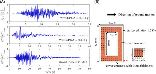
Figure 11 presents the seismic responses of the pier base section obtained from the transient dynamic analysis. The results show that the adjacent canyon terrain boundary amplifies dynamic effects compared with the 0° infinite fluid boundary, particularly in terms of peak response magnitudes. For example, under the excitation of Wave 1, the maximum base bending moment under the 90° boundary condition is 19.31% greater than that under the 0° infinite fluid boundary condition. Similarly, the base shear force exhibited considerable sensitivity to variations in the hydrodynamic added mass, which were induced by different canyon boundary conditions. Under Wave 2 excitation, the peak response associated with the 90° boundary condition is up to 45.27% greater than that under the 0° boundary condition. These pronounced increases in the peak seismic response can be attributed to the amplification of inertial forces along the pier's full height during ground excitation. Although the fundamental frequencies under the 90° and 0° conditions differ by less than 3%, the relatively low natural frequency of these high-pier bridge structures renders them highly susceptible to resonance when subjected to near-field, pulse-like ground motions. As a result, even slight variations in the dynamic characteristics induced by the canyon boundary can significantly increase the overall seismic response.
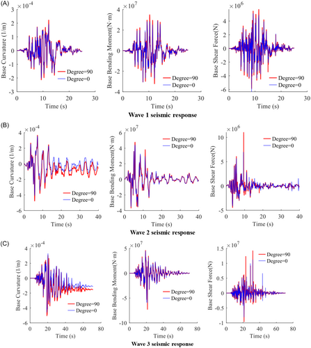
Apart from variations in peak response, nonlinear deformation near the pier base provides critical insights for structural assessment and earthquake-resistant design [34-37]. Notably, under the three earthquake records investigated, the 90° earthquakes exhibit larger base curvatures than the 0° earthquakes do. Owing to the longer duration and the associated accumulation of permanent deformation, the difference between the two cases in terms of residual drift is more pronounced in Waves 2 and 3. In particular, under Wave 3 loading, the residual base curvature in the 90° case is approximately 38.9% greater than that in the 0° case. Under the excitation of Wave 1, although the structure experiences multiple cycles of loading, the displacement amplitude in each cycle remains relatively small. This gradual entry into the nonlinear range leads to a more evenly distributed hysteretic energy dissipation process. Consequently, the residual deformation differences between the two boundary conditions were relatively minor.
5 Conclusions
- 1.
The canyon terrain boundary in deep reservoirs can induce additional hydrodynamic effects, increasing the mass added to submerged structures. The added mass represents a fixed quantity governed by the system's geometric parameters. Once the structural and canyon terrain parameters are determined, the distribution of earthquake-induced added mass along the structural height remains constant and is independent of structural motion.
- 2.
For canyon terrain parameters, reducing the pier-to-boundary distance and increasing the cliff angle can increase the added mass coefficient along the bridge height. The former mainly affects the pier base, whereas the larger canyon terrain slope angles induce a globalized effect to amplify the added mass along the entire pier height. In reservoir regions, seasonal fluctuations in water depth modify the vertical position of the influence zone induced by the canyon terrain boundary, with shallower depths leading to an upward shift along the pier height. The hydrodynamic effects induced by canyon topographical conditions are evident both perpendicularly and parallelly to the canyon terrain boundary.
- 3.
Owing to the interaction between the fluid‒structure coupled system and the rigid canyon wall boundary, the dynamic properties of the submerged structure are reduced because of the additional inertial effects. Although the associated frequency shift is relatively small, the seismic response remains highly sensitive to this change—particularly under pulse-type excitations—leading to notable amplification of the response at the pier base. The nonlinear analysis further reveals larger residual deformations when critical wall boundary conditions are presented.
This study highlights the critical importance of considering the effects of adjacent rigid canyon boundaries when estimating the seismic response of deep-water bridges. However, several limitations and assumptions remain in this study. These include the assumption of ideal rigid materials for cliff modeling and the emphasis on extreme canyon boundary cases in dynamic response analysis. Despite these constraints, this study can provide valuable insights and practical references for engineers and researchers, contributing to a more refined seismic analysis of deep-water bridge foundations under complex surrounding boundary conditions.
Acknowledgments
This study was supported financially by the National Natural Science Foundation of China (Grant Nos. U21A20154 and 52108167) and the Scientific Research and Development Project of China Railway Group Limited (2023-Special-01).
Conflicts of Interest
The authors declare no conflicts of interest.
Open Research
Data Availability Statement
All the data are presented in the published article.


