Hybrid simulation method with restoring force correction for structural testing characterized by incomplete boundary conditions
Abstract
Hybrid simulation is a powerful testing method that combines numerical analysis and physical experiments through on-line interaction. The substructuring technology enables hybrid simulation to evaluate the structural performance with large-scale specimens. However, this technology also increases the complexity of specimen boundary conditions. Due to limited equipment resources of structural laboratories, not all the degrees of freedom of the boundary conditions can be realized during tests, which will induce error to the experimental restoring forces and decrease of accuracy of hybrid simulation. In this case, the hybrid simulation method based on restoring force correction was proposed to reduce this error. In this method, the error in experimental restoring forces were corrected using an auxiliary numerical model of the experimental substructure. The effectiveness of the proposed method was verified through both theoretical analysis and numerical examples. This method was then adopted to evaluate the seismic performance of a spatial reinforced concrete frame with buckling-restrained braces numerically. Results showed that the proposed method can enhance the accuracy of tests compared to conventional hybrid simulation, and keep computational efficiency in the meanwhile.
1 INTRODUCTION
Hybrid simulation is a powerful testing methods for evaluating seismic performance of structures.1-3 Compared to traditional pseudo-dynamic test and shaking table test, a unique technology in hybrid simulation is the substructuring of the testing structure.4 By dividing the entire structure into the experimental substructure and the numerical substructure, large-scale or full-scale specimens can be tested in the laboratory.5, 6 These substructures are coupled at their interfaces through on-line interaction. By using the substructuring technology, hybrid simulation method has been applied to evaluate the structural responses with different types of specimen, including dampers,7 columns,8 planar frames,9 space structures,10 and so forth.
In the substructuring technology, it is important that all the boundary conditions can be accurately reproduced.11, 12 For the experimental substructure, it requires the loading instruments to realize the targets on all the degrees of freedom (DOFs) at the boundary. As normally the boundary conditions of the experimental substructures were loaded by actuators, it means the number of actuators should be greater than or equal to the number of specimen DOFs.13-15 To completely realize the specimen DOFs, some laboratories built six-DOF loading facilities, such as the Load and Boundary Condition Box (LBCB) at UIUC,16, 17 the Multi-Axial Testing System (MATS) at NCREE,18 the Multi-Axial Subassemblage Testing System (MAST) at the University of Minnesota,19 and so forth. However, not all the laboratories are capable of build large-scale six-DOF loading facilities, or have sufficient actuators for large-scale specimen. In this case, if the number of boundary DOFs exceeds that of laboratory actuators, the boundary conditions must be simplified and the loading of some DOFs may have to be ignored,20 which leads to incomplete boundary conditions.
Several studies had been conducted to deal with the problem of incomplete boundary conditions. For example, when taking a column as the experimental substructure, the contraflexure point was often chosen as the interface of substructures to avoid controlling the rotational DOF at the interface and reduce the number of boundary DOFs.21 Wang et al.9 and Hashemi et al.22 found that the position of contraflexure point is changeable, which would induce errors to the test results. Hence, an overlapping substructure testing method was proposed to allow accurate simulation of the real responses of a frame to seismic action. In this method, the boundary of experimental substructures is extended to numerical substructures to reduce the influences of changing in the position of the contraflexure point on experimental substructures. Although the method can avoid controlling on the rotational boundary DOF, it leads to a larger specimen. To overcome these problems, Wu et al.23 developed a scheme with a model updating method named online numerical simulation (ONS). Unlike the substructure technique of conventional hybrid simulation (CHS), this method computes structural responses by establishing a numerical model for overall structure, therefore there is no problem of incomplete boundary conditions. However, the model identification technique,24-28 for example the widely used unscented Kalman filter identification algorithm, may encounter problems of poor stability and low identification accuracy when applied to high-dimensional nonlinear systems.29, 30 Giotis et al.31 proposed a weakly-coupled hybrid simulation (WCHS) method, in which a position nearby the contraflexure point on a column was chosen as the substructural boundary. To consider the bending moment and rotation angle at the position, an auxiliary numerical model for the experimental substructure, which bears the bending moment and provides the rotation angle on the boundary of the experimental substructure, was also established. However, this method can only be applied to specimens with weakly coupled boundary DOFs.
To consider the incomplete boundary conditions with coupled DOFs, a hybrid simulation method with restoring force correction (HSRFC) was proposed. In this method, a numerical model is established for the overall structure and an auxiliary numerical model is constructed for the experimental substructures. Experimental substructures and the auxiliary numerical model are adopted to correct the restoring force obtained for the overall structure. On one hand, the structural responses of the proposed method are determined through computation of the numerical model of the overall structure, hence it does not encounter problems of incomplete boundary conditions. On the other hand, the restoring force obtained by the numerical model of the overall structure is corrected by using the experimental substructures and the auxiliary numerical model. This can reduce and even eliminate the influences of inaccurate modeling of experimental substructures in the overall structure.
The remainder of the research is arranged as follows. Section 2 introduces the principle of the proposed method and performs theoretical analysis to study its application range. A two-story two-bay planar frame structure is taken as an example in Section 3 to prove the feasibility and effectiveness of the proposed method. Furthermore, a virtual hybrid simulation on a reinforced concrete spatial frame with buckling-restrained braces (BRBs) is introduced in Section 4 to study the accuracy and computational efficiency of the proposed method for complex structures in engineering practice.
2 HYBRID SIMULATION METHODS CHARACTERIZED BY INCOMPLETE BOUNDARY CONDITIONS
2.1 Existing method
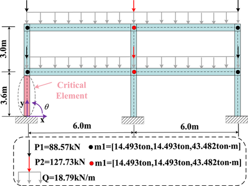
The existing hybrid simulation methods are explained by taking a two-story and two-bay steel frame structure32 as example. The left-hand column of the first story is regarded as the experimental substructure. The reference structure and experimental substructure are shown in Figure 1.
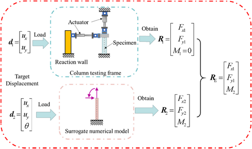
The boundary conditions of complex experimental substructures generally cannot be completely realized. The ignored boundary conditions will affect the accuracy of the test or cause different structural damage and failure modes,20, 33 which is known as the problem of incomplete boundary conditions. Therefore, the WCHS method for solving the problem of incomplete boundary conditions was proposed. In this method, the auxiliary numerical model will supplement the response of DOFs that cannot be obtained from the physical specimen. The process of obtaining the restoring force of the experimental substructure is shown in Figure 2.
2.2 Proposed hybrid simulation method with restoring force correction
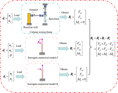
In the proposed methodology, two numerical models of the critical element are used to correct the restoring force of the physical specimen. The process of obtaining the restoring force of the experimental substructure is shown in Figure 3.
Furthermore, the proposed method was improved as shown in Figure 4. The auxiliary numerical model-Ⅰ and numerical substructure is combined into a whole structure to simplify the operation of the proposed method. The auxiliary numerical model-Ⅱ is also renamed the auxiliary numerical model. The advantage of this improvement is that the simulation in the finite element software can avoid the instability problem in the calculation of the divided numerical substructure.
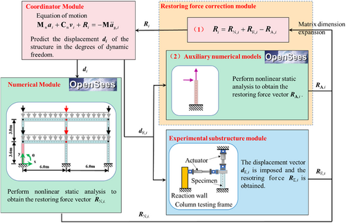
The framework of the proposed method consists of four modules: (1) a coordinator module, which is the main program for solving the EOM of the overall structure by using a time integration algorithm; (2) a numerical module, which performs static analysis of the overall structure using OpenSees to obtain the restoring force of the structure; (3) a module of the experimental substructure, where displacement commands are imposed to the physical specimen using transfer systems (such as a servo-hydraulic actuator, shaking table, and motor) and corresponding restoring forces are measured; and (4) a module of restoring force correction, which establishes and solves the auxiliary numerical model for the experimental substructure to determine corresponding restoring forces; the restoring force of the overall structure is corrected based on the experimental substructure and the auxiliary numerical model. The procedure of the proposed method is described as follows:
Step 1: The coordinator solves the discrete structural EOM using the time integration algorithm, to predict the displacement of the structure in the dynamic DOFs. Then the displacement is sent to the numerical module and the displacement of boundary DOFs of the experimental substructure is sent to the transfer systems and the auxiliary numerical model.
Step 2: In the numerical module, the numerical model of the overall structure performs static analysis to load the displacement response and determine the restoring force , which is then sent to the module for restoring force correction (1). Then the numeric model remains in its current state and waits for the next command.
Step 3: OpenSees is used in static analysis on the auxiliary numerical model to obtain the restoring force which is then returned to the module for restoring force correction (1). Then the auxiliary numerical model remains in its current state and waits for the next command.
Step 4: In the experimental substructure module, the displacement command is loaded using servo-hydraulic actuators. The measured restoring force is recorded and returned to the module for restoring force correction (1).
Step 5: In the module for restoring force correction (1), all kinds of restoring force will be dimensionally expanded. The restoring force provided by the numerical model of the overall structure is corrected using the obtained values of and , that is, . Then, the corrected restoring force R is fed back to the coordinator to calculate the displacement in the next cycle.
Step 6: Steps 1 to 5 are repeated until the completion of the testing.
2.2.1 Theoretical analysis of HSRFC method
The correction process of the restoring force of the overall structure is introduced by taking a more general structure form as an example, as shown in Figure 5. The structure subjected to conventional analysis is abstracted as a two-dimensional elastic structure. It is supposed that the left-hand substructure is the critical element that is subjected to physical loading in the laboratory; the rest of the structure is named the numerical substructure (which is clearly defined, and its mechanical behaviors can be simulated). The physical specimen has incomplete boundary conditions, so the auxiliary numerical model is built for the substructure using the proposed method, as illustrated in Figure 6. The numerical model of the overall structure is demonstrated in Figure 7.
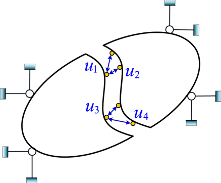
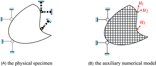
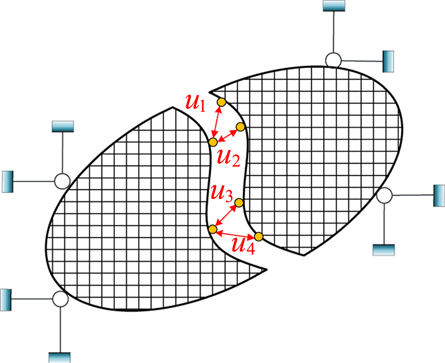
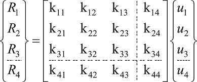
The relationship between the displacement and restoring force in Figure 5 is
The error of the restoring force of the proposed method is given by Equation (14): problems pertaining to incomplete boundary conditions are effectively solved, however, the proposed method also incurs errors in the auxiliary numerical model. The proposed method relies on the same technique as the method (WCHS) proposed in previous research31 such that, if the loaded and ignored DOFs are uncoupled or weakly coupled ( and ). Under the condition, the restoring force of the loaded DOFs is unaffected by the error in the model.
According to Equation (19), the proposed method can be superior to the CHS provided the stiffness of each item in the auxiliary numerical model is within twice the actual structural stiffness. Normally, the stiffness of the auxiliary numerical model can be obtained using material tests or parameter identification. In this case, Equation (19) can be satisfied and the accuracy of the proposed method can be guaranteed.
Structural responses of the proposed method are calculated using the numerical model of the overall structure, rather than combining restoring forces of substructures as used in the CHS. Therefore, the proposed method is not plagued with problems regarding incomplete boundary conditions. As the proposed method is developed based on the CHS, it inherits advantages of the conventional method, including simple operation, and high computational efficiency.
2.3 Data exchange based on TCP/IP
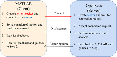
The numerical model of the overall structure and the auxiliary numerical model are realized using the finite element software OpenSees, which to a large extent benefits from the open-source nature of the software. Furthermore, MATLAB™ is adopted to achieve the coordinator module. Data including displacements calculated by the coordinator, and restoring forces provided by experimental substructures, auxiliary numerical model, and numerical model of the overall structure must be transferred between different modules. Either MATLAB™ or OpenSees provides methods for combining with other software and tools, such as the network communication channel (socket) based on TCP/IP. Herein, the data exchange framework used here is the TCP/IP-based client-server exchange strategy (Figure 8).
3 VERIFICATION OF PROPOSED METHOD
3.1 Overview of emulated structure
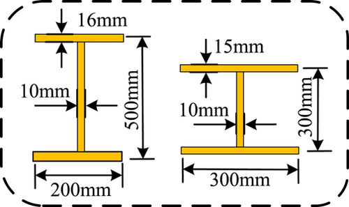
The structure and load are illustrated in Figure 1 with the story heights separately of 3.6 and 3.0 m and a bay width of 6 m. A uniformly distributed load Q of 18.79 kN/m is applied to the beams. A concentrated load P1 of 88.57 kN is applied to the side columns, with the translational mass and rotating mass of mass m1 being 14,493 kg and 43,482 kg m, respectively. The concentrated load P2 on the central column is 127.73 kN, and the translational mass and rotating mass of mass m2 is 24,044 kg and 72.144 kg m, respectively. The emulated structure used in the section is illustrated in Figure 9, I-shaped cross-sections are used in the beam and column, with dimensions of 200 mm × 500 mm × 10 mm × 16 mm and 300 mm × 300 mm × 10 mm × 15 mm, respectively.
The experimental substructure is the left-hand column in the first story of the structure, and only the horizontal and vertical DOFs are controlled at the interface. In this virtual hybrid simulation, the experimental substructure is also established in OpenSees, and the parameters of its constitutive model are all true values. Whereas, parameters of the constitutive model of the auxiliary numerical model are estimates showing certain deviations from the true values. Parameters pertaining to feature points of materials are listed in Table 1, and parameters not listed therein are values recommended by the OpenSees user manual.34
| Constitutive model | Yield strength Fy/MPa | Elastic modulus Es/GPa | Strain-hardening ratio bs | |
|---|---|---|---|---|
| True values | Steel02 | 270 | 200 | 0.01 |
| Estimated values | Steel02 | 300 | 210 | 0.03 |
3.2 Test methods setting
Only the first 20 s of the El-Centro seismic wave (NS, 1940) is used, with the peak ground acceleration of 200 gal. In the coordinator module, the EOM is solved by using the central difference method, with the time integration step of 0.005 s. Then, the dynamic simulation of an overall structure with true values of material parameters is performed, and its results are used as the reference solution.
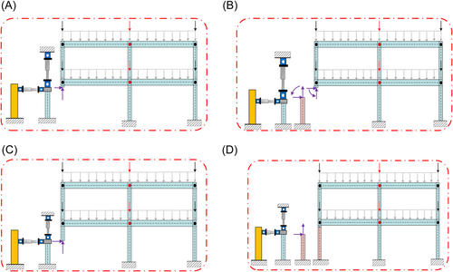
To evaluate the influences of incomplete boundary conditions on the test accuracy, this hybrid simulation method with incomplete boundary conditions and no model error is implemented (denoted by BC1ME0), as shown in Figure 10A. The second is the WCHS method (Figure 10B); the third method is the CHS, which takes a half-column as the physical specimen (CHS) (Figure 10C); the fourth is the proposed method (Figure 10D).
3.3 Results analysis
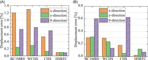
Through finite element analysis using the aforementioned methods, the displacement errors of the top story in three directions (x, y, and θ) are obtained, as shown in Figure 11. It is evident that the incomplete boundary conditions greatly affect the test accuracy. The WCHS method does not reduce adverse influences of incomplete boundary conditions because the method is only applicable to cases of weak coupling and small model errors. For the DOF in the horizontal x-direction, the CHS method reduces the RMSE incurred by incomplete boundary conditions from 120% to 50%. Therefore, CHS is a relatively favorable method when solving problems pertaining to incomplete boundary conditions. The evaluation indices RMSE and RE are the lowest when using the proposed method.
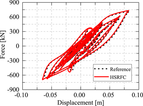
The relationship between the top horizontal displacement and base shear force of its structure obtained using the proposed method and the reference solution is displayed in Figure 12. As shown, the hysteresis loops obtained using the proposed method differ slightly from those of the reference solution. This is because, in the proposed method, there is a modeling error for the experimental substructure in the numerical model of the overall structure. Despite correction by the experimental structure and the auxiliary numerical model, the error still cannot be eliminated due to the presence of coupling. However, the results of the proposed method are similar to the reference solution, proving the effectiveness of the proposed method.
4 APPLICATION TO COMPLEX STRUCTURES IN CIVIL ENGINEERING
4.1 Reference structure
The structure selected in this section has eight stories as well as three and seven bays in two horizontal directions. It is designed according to the Chinese Code for Seismic Design of Buildings.35 The first story is 3.9 m high, and the other stories are all 3.5 m high, so the total height of the structure is 28.4 m. The total length in the length direction is 45.5 m, with each bay being 6.5 m wide; the length in another horizontal direction is 17.5 m, with a corridor of 2.7 m wide, and the remaining two bays are both 6.5 m wide. The structural plane is shown in Figure 13 and details of the structure are provided elsewhere.36
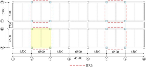
Layout plane of the selected structure.36
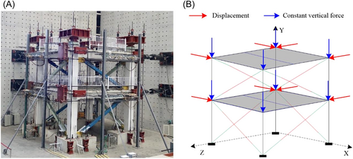
A one-bay eight-story equivalent structure is extracted from the prototype structure. The lower two stories of the equivalent structure are regarded as the experimental substructure to assess its structural performance. The experimental substructures are subjected to bidirectional loading and three planar DOFs in each story are considered, namely, the horizontal x and y DOFs and the in-plane rotational DOF. Four actuators are used to apply the requisite loads.
Structural analysis is conducted using the finite element software OpenSees. Force-based nonlinear beam-column elements are used to simulate beams and columns of the structure. To consider the assistance of plates to bending performance of beams, the cross-section of the beams is deemed to be T-shaped, while that of columns is a rectangle. Each BRB component in the structure is simulated using three elements, namely, elastic beam-column elements on both ends, and nonlinear energy-dissipating beam-column elements in the middle, which was verified elsewhere,37 as shown in Figure 14.
4.2 Methods information for comparison
The CHS,10 ONS,23 and the proposed method were applied to the above complex structure. Because the proposed method has the modeling error of the auxiliary numerical model, it is supposed that the material parameters of concrete and steel used for producing BRBs in the auxiliary numerical model all have deviations from the true values, as listed in Table 2. The yield strength, elastic modulus, and strain-hardening rate of the reinforcement used in beams and columns are 500 MPa, 200 GPa, and 0.01, respectively; the yield strength of the stirrups is 400 MPa.
| Concrete01 | Steel02 | |||||||
|---|---|---|---|---|---|---|---|---|
| Cover/Conf | fc/MPa | ε0 | fu/MPa | εu | E/GPa | fy/MPa | b | |
| True values | Cover | 33.4 | 0.00179 | 16.7 | 0.00358 | 200 | 285 | 0.005 |
| Conf | 37.2 | 0.002815 | 15.38 | 0.00141 | ||||
| Estimated values | Cover | 18.0 | 0.0025 | 9.0 | 0.004 | 210 | 315 | 0.03 |
| Conf | 22.0 | 0.0035 | 11.00 | 0.02 | ||||
- Abbreviations: Conf, confined concrete; Cover, the cover concrete.
The structure involves numerous parameters to be identified and observed quantities in two stories and two directions. Therefore, it is worth noting that the UKF algorithm in ONS shows low convergence and accuracy when used to identify high-dimensional parameters and observed quantities. The identification effect of ONS for numerous parameters remains to be further studied.
4.3 Seismic records and integration algorithm
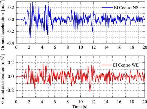
The selected seismic records are El Centro (1940, NS) and El Centro (1940, WE), and only the first 20 s of seismic waves are used. The amplitude of NS seismic waves is 400 gal. The seismic waveforms are illustrated in Figure 15.
In the virtual hybrid simulation, the dynamic equation is solved using the central difference algorithm with a time interval of 0.01 s. Nonlinear dynamic analysis is applied to the overall structure that has correct material parameters in OpenSees and the results are used as the reference solution.
4.4 Accuracy and computational efficiency analysis
To evaluate the effect of hybrid simulation more intuitively, Figure 16 provides the time history of displacements of the top story in two horizontal directions obtained using the three methods. The results of the proposed method and ONS are both in good agreement with the reference solution compared with the CHS. The slight difference when using ONS results from the numerous parameters to be identified and therefore the lowered stability and accuracy of the UKF; the error of the proposed method stems from that of the auxiliary numerical model. It is worth noting that the proposed method is not plagued with problems of stability compared with ONS. In addition, the accuracy of the proposed method meets engineering requirements using model calibration.
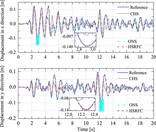
Figure 17 illustrates the RMSETH curves of the first story and the eighth story of the structure in two directions. According to the finally converged values of the curves, the proposed method is found to have improved accuracy compared with the CHS, only inferior to ONS. The RMSETH curves indicate that the curve of ONS fluctuates in the largest range, especially in the first three seconds, during which the error even exceeds that of the CHS. In comparison, the RMSETH curve of the proposed method is the most stable. This phenomenon is mainly because there were not enough experimental data for parameter identification in the early stage of the test, thus the parameters had not converged yet. Therefore, it is possible that combining the proposed method with ONS in the future research, by using the proposed method at the early stage of the test, while using ONS after the identified parameters converge.
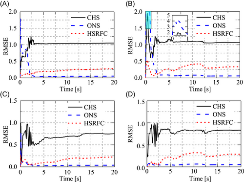
Intersects with that of ONS at a point. This indicates that the proposed method is combined with ONS in future research to improve the stability of the latter.
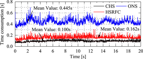
To record and reserve the time taken by the three methods in each time integration step, a Lenovo laptop (CPU: Intel® Core™ i7-9750H CPU @ 2.6 GHz 2.59 GHz; RAM: 16.0 GB) was used to run the simulations five times. The average time of the five times was calculated and then the statistical time curves were plotted (Figure 18). As shown, the proposed method takes a shorter time and the average computing time of each integration step is 0.162 s, only second to that of the CHS (0.100 s). The ONS method takes the longest time and its average computing time is 0.445 s in each integration step, with large fluctuations of 0.32 to 0.70 s. In summary, the proposed method saves three-fifths of time compared with ONS and its time consumption mainly fluctuates from 0.1 to 0.3 s, which is far less than the loading time in physical experiments. Therefore, it is feasible to use the proposed method to evaluate the performance of complex structures in engineering practice.
5 CONCLUSIONS
- (1)
The restoring force of the experimental substructure was corrected based on the experimental feedback and an auxiliary numerical model, which improves the accuracy of hybrid simulation with incomplete boundary conditions. Through theoretical derivation, the proposed method was proved to have a broader applicational range compared to the CHS.
- (2)
Numerical analysis was performed on hybrid simulation of a two-story two-bay steel frame structure, the influences of incomplete boundary conditions on the test accuracy were compared. Results showed that the proposed method can significantly reduce the adverse influences of incomplete boundary conditions and performances with higher accuracy than CHS and WCHS.
- (3)
The accuracy and computational efficiency of CHS, ONS, and the proposed method were compared by virtual hybrid simulation on a spatial reinforced concrete structure with BRBs. Results showed that the proposed method and the CHS have similar computational efficiency while the former provides better accuracy. Despite slightly lower accuracy than ONS, the proposed method has much better stability and higher computational efficiency.
ACKNOWLEDGMENT
The authors gratefully acknowledge the financial supports provided by the National Natural Science Foundation of China [Grant No. 51878525; 52008320; 52078398; 51908231], the Major Science and Technology Project in Hainan Province [Grant No. ZDKJ2021024], the Hainan Special PhD Scientific Research Foundation of Sanya Yazhou Bay Science and Technology City [Grant No. HSPHDSRF-2022-03-014] and the open project of the Key Laboratory of Earthquake Engineering Simulation and Seismic Resilience of China Earthquake Administration.
CONFLICTS OF INTEREST
The authors declare no conflicts of interest.


