Interface Engineering on Constructing Physical and Chemical Stable Solid-State Electrolyte Toward Practical Lithium Batteries
Abstract
Solid-state lithium batteries (SSLBs) with high safety have emerged to meet the increasing energy density demands of electric vehicles, hybrid electric vehicles, and portable electronic devices. However, the dendrite formation, high interfacial resistance, and deleterious interfacial reactions caused by solid–solid contact between electrode and electrolyte have hindered the commercialization of SSLBs. Thus, in this review, the state-of-the-art developments in the rational design of solid-state electrolyte and their progression toward practical applications are reviewed. First, the origin of interface instability and the sluggish charge carrier transportation in solid–solid interface are presented. Second, various strategies toward stabilizing interfacial stability (reducing interfacial resistance, suppressing lithium dendrites, and side reactions) are summarized from the physical and chemical perspective, including building protective layer, constructing 3D and gradient structures, etc. Finally, the remaining challenges and future development trends of solid-state electrolyte are prospected. This review provides a deep insight into solving the interfacial instability issues and promising solutions to enable practical high-energy-density lithium metal batteries.
1 Introduction
Among various energy storage devices, rechargeable lithium-ion batteries (LIBs), presently dominating the most proportion of our current battery market, have been widely used in powering portable electronic devices, electric vehicles, and hybrid electric vehicles because of their high energy density and long service time.[1-7] However, the current commercial LIBs have approached the theoretical energy density limitation (300 Wh kg−1).[8-11] Meanwhile, the organic liquid electrolyte is flammable, raising safety concerns. Therefore, solid-state lithium batteries (SSLBs) using solid-state electrolyte (SSE) have attracted lots of interest due to their higher energy density and safety compare to traditional LIBs.[12-16] Continuous efforts have been devoted to developing high-energy-density SSLBs and revealing their fundamental electrochemistry.
SSE can be divided into three categories: organic polymer solid electrolyte, inorganic solid electrolyte, and their composites.[17] Organic polymer solid electrolytes have been considered as the potential candidates in practical applications due to their high flexibility, good compatibility with electrodes, and easy processability. Solid polymer electrolytes consist of polymers and Li salts, where Li ions transfer by chain segment motion or ion hopping. However, the high crystallinity at room temperature restricts Li-ions migration, resulting in an inferior ionic conductivity (<10−8 S cm−1) and a low transference number (0.2–0.3). Meanwhile, the organic electrolyte may be destroyed by Li dendrites due to its insufficient hardness, resulting in a short lifetime.[18] In contrast, inorganic solid electrolytes have attracted enormous interests due to their thermomechanical stability, high ionic conductivity (>10−3 S cm−1), and Li-ion transference number (~1), where Li ions diffuse in the interstitial sites, vacant lattice sites, and along the grain boundaries. Nevertheless, the poor wettability with the electrode leads to the inhomogeneous contact between the electrolytes and electrodes, causing sluggish charge transfer at the solid-state interface. Correct, electrolytes can be chemically unstable when they contact with a Li anode. This instability leads to their decomposition, resulting in the formation of a solid electrolyte interface (SEI). The presence of the SEI layer increases the impedance for ionic diffusion, which can hinder the movement of ions and impact charge transport. In this regard, to achieve high-performance SSLBs, SSE should possess a high ionic conductivity (>10−4 S cm−1), a wide electrochemical working potential window (>5 V), superior interfacial stability, and mechanical strength.[19, 20] Since a single inorganic or organic solid-state electrolyte cannot satisfy all these requirements, organic/inorganic hybrid electrolytes have been developed. The ionic conductivity of polymer electrolytes has been enhanced by introducing inorganic electrolyte or plasticizers to reduce the crystallinity of polymers.[21-24]
The interfacial physical/chemical instability between SSEs and anodes/cathodes deteriorates the performance of SSLBs. To improve the interfacial compatibility between cathode and SSE, the commonly used strategy is the introduction of an extra layer or adding ionic liquid.[25] Various organic or inorganic buffer layers were constructed to optimize the anode/electrolyte interface and ensure the intimate physical contact with the electrolyte.[26] Meanwhile, to achieve desirable anode/SSE interfaces, constructing Li-alloys or protective layers on Li metal have been widely studied to guide even lithium deposition and suppress the side reactions between Li metal and the polymer electrolyte.[27-30] Besides, rational design of SSE architectures (double-layered or multi-layered electrolytes) can also improve the ionic conductivity and enhance interfacial physical/chemical stability between the electrode and electrolyte.[31-34] It can be harvested by changing the types and concentration of Li salts, optimizing the electrolyte components, and adjusting the highest/lowest occupied molecular orbital of the electrolyte, resulting in an enlarged electrochemical working window and suppressed oxidation/reduction at the cathode/anode interface.[32, 35-37] Furthermore, several strategies have been proposed to improve the mechanical strength of polymer electrolytes and optimize the performance of SSLBs. These strategies encompass the physical blending of one-dimensional organic fillers, grafting copolymers, and the incorporation of inorganic fillers. By employing these techniques, the aim is to improve the uniformity of Li-ion flux and suppress the formation of dendritic structures of lithium within the battery. Ultimately, these solutions all contribute to the stabilization of the SSE interface and enhanced electrochemical performance of SSLBs.[38-40]
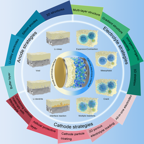
Thus, we propose the recent advances in rational design of solid-state electrolyte for lithium batteries toward practical applications (Figure 1). First, we would like to highlight the challenges associated with interfacial stability and charge transfer in both inorganic materials and polymers. Second, the current strategies of structure design and interface modification are summarized to improve the ionic conductivity and interfacial physical/chemical stability. Finally, the future directions and perspectives are proposed toward construing practical solid-state electrolytes. We believe that this comprehensive story provides deep considerations and solutions to the interfacial issues affecting the performance, which paves a new pathway toward constructing safe, high-energy-density lithium batteries.
2 Challenges on Anode–Electrolyte Interface
2.1 Anode–Electrolyte Interfacial Physical Instability
In all-solid-state lithium batteries, the interface between the anode and the electrolyte suffers from two main physical instability problems: thermal instability and mechanical instability. Most inorganic solid-state electrolytes are made by high temperature sintering and are generally thermally stable, while organic solid-state electrolytes are less thermally stable and are prone to decompose at higher temperatures.[41, 42]
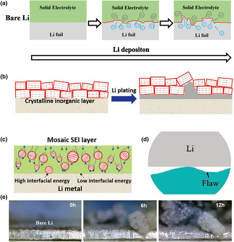
The problem of mechanical instability is mainly manifested in the growing process of lithium dendrites (Figure 2a,b).[43, 44] When utilizing inorganic solid electrolytes, one drawback is that the electrolyte may not fully wet the surface of the lithium anode. Additionally, the flatness of the side in contact with the lithium anode may not be sufficient, resulting in the formation of voids and gaps between the inorganic solid electrolyte and the lithium anode. This issue can lead to an undesirable increase in interfacial impedance (Figure 2c,d).[45] Due to the space charge effect, Li+ is also preferentially deposited in these defects, which leads to the rapid spread and growth of dendrites at the grain boundaries of the inorganic solid electrolyte (Figure 2e).[46-52] In organic solid-state electrolytes, the growth of lithium dendrites is mainly caused by the uneven deposition of Li+ across the electrolyte film on the lithium anode, which results in a local increase in current and accelerates the damage process at the electrolyte–lithium anode interface. Moreover, organic solid-state electrolytes typically have low mechanical strength, which makes them more susceptible to perforation or damage caused by growing lithium dendrites, ultimately leading to battery failure.[53-57]
During the battery preparation process, the stacking pressure of the battery will have a great impact on the battery performance and interface stability. When the stacking pressure is small, the electrode materials will have point-to-plane contacts with the SSE, resulting in an increased internal resistance. As the stacking pressure increases, the contact between the electrode materials and the SSE becomes plane-to-plane, and the battery performance and interface stability are improved. When the stacking pressure further increases, it may cause the electrode materials and SSE to crack. Meanwhile, the contact between the electrode materials and the SSE changes to a point-to-point form, reducing the effective contact area and increasing the actual unit area current, thus, deteriorating both performance and interface stability.[58] Besides, the manufacturing pressure also has a great impact on the battery's performance and interface stability. When the manufacturing pressure of the battery is small, it will lead to poor contact between the electrode materials and the SSE, resulting in the decreased ionic conductivity and performance of the battery. With increasing manufacturing pressure, the interface contact will be improved and the battery performance will be enhanced. When the manufacturing pressure further increases, it may destroy the electrode materials and SSE and decrease the interfacial wettability, causing a rapid decline in battery performance.
2.2 Anode–Electrolyte Interfacial Chemical Instability
In addition to physical instability, there also exists the issue of chemical instability between the lithium anode and the solid electrolyte. The chemical instability of the interface is mainly considered from two perspectives: thermodynamic instability and kinetic instability. Due to the strong reductive nature of the lithium anode, most SSE will react with Li metal at the interface upon contact to form a passivation layer, which is less thermodynamically stable and restricts the transport of lithium ion in a passivation layer.[59-63] Meanwhile, as the SSE and lithium anode are always heterogeneous, a chemical potential gradient is formed at the interface, which causes the generation of a space charge layer. The space charge layer can lead to a significant increase in interfacial resistance. General speaking, the selection of a more stable electrolyte can effectively slow down the formation of the passivation layer, thus increasing the capacity and lifetime of the battery. However, the continuous loss of the electrode/electrolyte interface over long storage periods will still lead to a reduction in performance.[64-69] Furthermore, the electrochemical stability of the interface between SSE and the lithium anode has a significant impact on the performance of lithium batteries. The ideal SSE should have a wider window of electrochemical stability to restrict side reactions with the lithium anode. The decomposition of SSE at the interface, forming an interfacial layer, is unfavorable for Li+ transport, leading to an increase in interfacial resistance and affecting the cycle lifetime and capacity of the battery.[70, 71]
The energy density of the anode materials also affects the chemical stability of the interface. The high capacity and low working voltage of anode materials will increase the energy density. Increasing the anode capacity will lead to the large volume change of anode materials during the charge and discharge process, such as lithium metal, silicon, etc. Meanwhile, the low working voltage of the anode will decrease the stability of the solid-state electrolyte. Both the huge volume changes and low working voltage will lead to the instability and interface reactions between the anode and SSE.[72]
3 Resolutions to Mitigate Anode–Electrolyte Interfacial Instability
3.1 Interface Strategies
The use of interfacial layers has been shown to be an effective solution for solving the problem of poor physical stability at the lithium anode/solid electrolyte interface. Interfacial layers can effectively promote the uniform deposition of Li+ and enhance the wettability of the lithium metal, thereby inhibiting the growth of lithium dendrites. Generally, there are two types of interfacial layers: interfacial protective layers and in-situ polymerized interfacial layers.
3.1.1 Interfacial Protective Layers
The anode interface protective layer should have excellent anti-reduction capability, resistance to mechanical deformation and volume changes, excellent stability, and superior mechanical strength. Part of these freestanding interface layers are constructed on solid electrolytes, such as Li7La3Zr2O12 (LLZO) and Li6.7La3Zr1.7Ta0.3O12 (LLZTO), etc. Inorganic solid electrolytes typically exhibit high interfacial resistance and uneven deposition of Li+ ions, which can facilitate the growth of lithium dendrites, further penetrating the electrolyte membrane and leading to short circuits. By implementing a freestanding interfacial layer with high ionic conductivity, low thickness, excellent stability, and resistance to damage during cycling, the deposition of Li+ ions can be more uniform, mitigating the formation of dendrites and reducing the risk of short circuits. These freestanding interfacial layers on the solid electrolyte are partly organic boundary layers. Chen et al. employed a composite coating consisting of carbonized phenolic resin and polyvinyl butyral layers on the surface of the solid electrolyte to improve the interfacial wettability of the LLZTO solid electrolyte with the lithium anode, further improving electrochemical stability.[73] The results demonstrated that the battery exhibited excellent rate performance and a flat voltage plateau with minimal polarization throughout the testing process, indicating a stable electrode–electrolyte interface in the battery system. For the inorganic interfacial layer, Lee et al.[74] addressed the problem of lithium dendrite generation by coating a SnF2 layer on LLZTO, which can effectively form a thin LiF layer with a Li-Sn alloy on the solid electrolyte surface to enhance adhesion to the lithium metal, thereby reducing interfacial resistance and preventing short-circuiting (Figure 3a). The prepared Li-symmetric cells achieved a stable constant current cycle of over 1000 h at 0.5 mA cm−2 and a robust cycle life of over 600 cycles at 1.0 mA cm−2 for the full cell. Besides, Su et al. reported the preparation of a thin lithium phosphorus oxynitride (LiPON) interlayer between Li6PS5Cl (LPSCl) SSEs and lithium metal anodes by radiofrequency sputtering, which facilitated rapid lithium-ion transport at the SSE/lithium metal interface, while LPSCl SSEs with a LiPON interlayer also showed excellent wetting interactions with the heated lithium metal (Figure 3b,c).[75] The LiPON thin interlayer exhibited lithium-ion conductivities of 0.69 and 0.98 mS cm−1 at 25 and 30 °C, respectively. The prepared symmetric cells achieved a high critical current density value of 4.1 mA cm−2 and stable cycling of over 1000 h at 0.5 mA cm−2 and 30 °C.
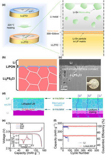
Except for solid-state electrolyte, the interfacial protective layers coated on the lithium anode are usually inorganic boundary layers. For example, Jin et al. successfully manipulated the interfacial wettability of the lithium metal anode by spreading a layer of liquid metal between LiF and Li anode oxides using an artificial hydride solid electrolyte layer. This interlayer structure on the anode has high ion transport, electron shielding, and high mechanical strength (Figure 3d).[76] The resulted Li/superficially oxidized LM (soLM)/Li composite anode can be cycled for more than 4000 h at 0.5 mA cm−2 and 1 mAh cm−2 in a symmetric cell, with a small interface impedance. The Li/soLM/LiF||LiFePO4 cell showed reversible charging and discharging performance with a capacity of approximately 150 mAh g−1. The Li/soLM/LiF||LiFePO4 battery maintains high Coulombic efficiency (≈99.9%) and high capacity (95–112 mAh g−1) over 1000 cycles (Figure 3e, f). Wang et al.[43] constructed an ultrathin LiF/Li3Sb hybrid interfacial layer by spraying commercial lithium foils with SbF3 precursor. This interfacial layer effectively improved the deposition of lithium ions and enhanced the stability of the solid electrolyte/anode interface through the lithium-loving materials of LiF and Li3Sb. Li et al. developed an ordered LiF-rich and Li bis(2-methoxyethyl) aminosulfide (Li-MAS) layers Janus interface to stabilize the lithium metal anode.[44] The dense crystalline LiF layer with uniformly distributed grains not only provided the necessary mechanical hardness but also offered fast and uniform lithium-ion transport through the LiF grain boundaries. Li-MAS layers containing polyethylene oxide (PEO)-like organic chains have been proven to be effective in facilitating the transfer of Li ions. Besides, the polar functional groups in the Li-MAS layers exhibited a strong affinity for Li ions, thereby promoting the uniform distribution of Li ions and their interfacial properties.
3.1.2 In-Situ Polymerized Interfacial Layers
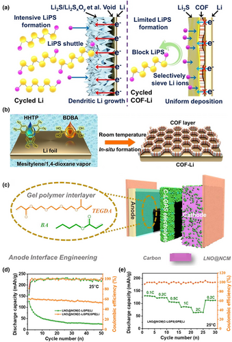
During the charging and discharging process of the solid-state lithium battery, the transportation of Li+ ions occurs in the SSE, which is accompanied by the conduction of electrons. When electrons are conducting, they will transform Li+ ions into Li atoms, which will accumulate in the gaps and defects of the electrolyte. This can lead to poor electrolyte–interface contact, an uneven electric field, localized high current, accelerated growth of lithium dendrites, and a decreased battery lifespan. In order to inhibit the growth of Li dendrites and mitigate side reactions at the electrolyte/anode interface, a thin SEI is fabricated by in-situ polymerization. These SEIs enable selective ions screening, prevent electron conduction, and facilitate uniform deposition of Li+. For example, He et al. fabricated a thin covalent organic framework (COF) on the lithium metal anode by in-situ technique. This protective layer can guide the uniform deposition of Li+ ions, thus inhibiting the growth of dendrites while also preventing the generation of inactive material (Figure 4a,b).[46] Jiang et al.[77] prepared a gel electrolyte to isolate Li10GeP2S12 (LGPS) from the lithium metal cathode by in-situ thermal polymerization to improve the battery life and performance (Figure 4c–e). Sheng et al.[78] proposed the PEO electrolyte doped with trace amounts of iodine to achieve a stable interfacial phase on the lithium metal surface. The triiodide ion (I3−) produced by the iodine additive could cooperate with the -COC- bond of PEO to increase the ionic conductivity of solid polymer electrolyte (SPE). The doped interfacial phase contains I3− and IO3−, which react spontaneously with the dead Li and Li2O of the initial interfacial phase, resulting in a smooth Li metal surface, and ultimately leading to a significant improvement in interfacial resistance and dendrite inhibition.
3.2 Anode Strategies
3.2.1 Silicon-Based Anodes
Since Li metal is considered as one of the most promising anode candidates for high-energy density solid-state batteries, the dendrite formation could cause a fire accident and explosion, threatening human beings' lives. Thus, novel silicon-based electrodes have been reported to improve the safety of solid-state batteries. The lithiation potential of silicon at 0.4 V (vs. Li/Li+) not only prevents the risk of lithium plating and lithium dendrite growth but also offers a higher energy density than using other alloy anodes. In addition to this, silicon anodes offer the advantages of abundant natural resources, low cost, and environmental friendliness. The main common silicon-based anodes are Li-Si alloy and SiOx (1 ≤ x ≤ 2).[79-81] Li-Si alloy electrodes can be achieved by electrochemical prelithiation and the physical blending of Si particles with Li metal foil or powder in an inert atmosphere, resulting in a high ion conductivity. This Li-Si alloy electrode has a smaller expansion during the charging and discharging process and is subjected to more dispersed stress, which can timely supplement lithium loss. For example, Yan et al. synthesized a hard-carbon-stabilized Li-Si alloy anode, in which the sintering of silicon leads to the transformation of micrometer particles into a dense continuum (Figure 5a).[82] The formation of a 3D ion/electron conductive network composed of plastic-deformed lithium-rich phases (Li15Si4 and LiC6) in the anode can expand the active area and alleviate stress concentration, thereby improving electrode dynamics and mechanical stability. The SSLBs using LiNi0.8Co0.1Mn0.1O2 can achieve 5000 cycles at 1C (5.86 mA cm−2) under a high loading of 5.86 mAh cm−2.
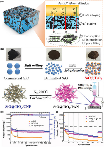
SiOx has a high capacity but poor cycling performance, mainly due to the small interfacial contact area between the anode and the SSE and the insufficient formation of the SEI layer.[84-86] By reducing the particle size of SiOx and constructing SiOx/C composites, the interfacial performance of the cell can be effectively improved, and the Coulombic efficiency of the cell can be enhanced.[87-90] For example, Cai et al. proposed a novel dual-constrained SiO@TiO2/carbon nanofiber (SiO@TiO2/CNF) composite materials (Figure 5b).[83] It can be well supported that a 3D interconnected CNF network ensured good mechanical integrity and conductivity. At the same time, it has advantages such as high storage capacity, high Coulombic efficiency, as well as good rate ability and recyclability (Figure 5c,d). Zhao et al.[91] prepared a dual modulated SiO particles by graphene cord and Si/SiO2 composite for the anode. This electrode exhibited better lithium storage capacity and tolerance to volume expansion, and displayed excellent stability with a high specific capacity. Liu et al. synthesized monodisperse SiOx/C microspheres with tunable size and well-controlled carbon content by a simple sol–gel route.[92] A reversible capacity of 999 mAh g−1 can be achieved at the current density of 100 mA g−1, retaining 853 mAh g−1 after 150 cycles. At the current density of 500 mA g−1, the SiOx/C delivered a specific capacity of 689 mAh g−1 and maintained 91.0% of the capacity after 400 cycles. SiOx (1 ≤ x ≤ 2) can be also lithiated by the same methods used in LixSi, which is reported as the anode to construct all-solid-sate lithium batteries with higher safety than using Li metal.
3.2.2 Li-Alloy Electrodes and 3D Structures
In addition to lithium metal and Li-Si alloys, other Li-alloys are also used as anodes in all-solid-state batteries, such as Li-In, Li-Al, Li-Zn, Li-Mg, Li-Si, and Li-Sn alloys. These alloy electrodes exhibit higher voltages compared to lithium metal electrodes, and they form more stable interfaces with the solid-state electrolyte. Additionally, their higher lithium-ion diffusion coefficients facilitate the uniform deposition of lithium ions.[93] For example, Huang et al.[94] evaluated the ability of Li-Zn, Li-Si, Li-Sn, and Li-Al alloys to inhibit dendrites. They found that Li-Al alloys showed the most excellent dendrite inhibition ability. Krauskopf et al.[95] found that Li-Mg alloys were effective in preventing the generation of macroscopic pores at the interface between the lithium anode and the solid electrolyte. Santhosha et al.[96] demonstrated that Li-In alloys are more conducive to lithium-ion diffusion and could form a more stable interface with the solid-state electrolyte. Hänsel et al.[97] found that preparing block-shaped alloy electrodes alleviated the problems associated with morphological instability and extrusion, which ensured good interfacial contact between electrolyte and electrode.
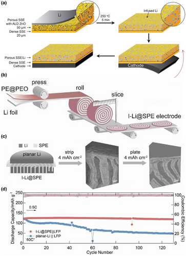
Most existing strategies have been developed based on planar Li-SSE contacts. However, there are two main limitations to such planar contacts. First, the limited contact area between Li and SSE results in a high local current density during Li stripping and plating. Second, the volume of the Li metal changes drastically, mainly in the thickness direction, thus breaking the interfacial connection between Li and SSE. To address these two challenges, the design transition from planar Li-SSE contacts to 3D interfaces has been demonstrated as an effective solution. Liu et al. developed a garnet-based asymmetric 3D framework with a porous dense bilayer structure as the solid-state Li metal body to address the unstable anode volume and limited energy density of solid-state Li metal batteries.[98] The bilayer design not only provided a highly conductive and continuous ion pathway for lithium-ion transport but also a mechanically and electrochemically stable porous framework for stabilizing the lithium metal cathode. The lithium metal body (porous layer) and the solid electrolyte/diaphragm (dense layer) are integrated into a single sheet with high flatness on the dense side (Figure 6a). Yang et al. have designed a fork-finger Li-SPE (I-Li@SPE) framework to pioneer the demonstration of 3D interfaces in polymer-based all-solid-state batteries.[99] The fork-finger Li@SPE design extended Li stripping/plating from the planar Li-SSE interface to 3D, thereby reducing local current density and suppressing void formation. In addition, the I-Li@SPE framework accommodated the volume change over a larger 3D interface region than 2D planar Li, providing additional degrees of freedom and reducing interfacial fluctuations at the Li-SPE interface. As a result, I-Li@SPE has a smoother interface and lower interfacial resistance than planar Li (Figure 6b,c). I-Li@SPE achieved a current density of 1 mA cm−2 and a significantly high capacity cycle of 100 h at 4 mAh cm−2 at 0.4 mA cm−2 (Figure 6d).
4 Challenges on Cathode–Electrolyte Interface
4.1 Cathode–Electrolyte Interfacial Physical Instability
The physical stability problem between the cathode and the SSE can be similar to that of the anode, which can be divided into thermal instability and mechanical instability. When the SSE comes into contact with the cathode, the thermal stability at their interface decreases rapidly and then starts to spread toward the interior of the material, ultimately causing thermal failure at the interface.[100] At the same time, the thermal decomposition can lead to the production of some Li-free salts, which reduce the Li+ transfer efficiency. Moreover, most of the Li-free salts from the thermal decomposition have a low-melting point, which further reduces the interface thermal decomposition temperature and accelerates the interface failure. All of this can ultimately result in a rapid decrease in battery capacity and lifetime.[101-107]
The main reason for the mechanical instability of the interface is the continuous volume change during the charging and discharging of the battery. For the cathode, dislodgement and embedding of Li+ in the cathode material can lead to changes in phase and lattice expansion or contraction, resulting in a change in size. In turn, this causes large stress changes at the interface between the cathode and SSE, leading to interface failure, the formation of voids, and difficulty in Li+ transfer.[108-111] These issues can lead to significant losses in battery capacity and lifespan. In addition, it also causes the cathode material to glass with the conductive agent and the collector, and the cell impedance increases significantly, which has a detrimental effect on the electrochemical performance. For electrolytes, the inorganic electrolytes often have a point-to-point contact with the cathode material, which lead to a huge resistance between the electrolyte and the electrode. Furthermore, it can cause the production of dead lithium in the voids therein. Although organic electrolytes generally have better interfacial wetting performance and low interfacial impedance compared to inorganic ones, they do not play a large role in limiting the volume change of the cathode material due to their low mechanical strength.[112-114]
4.2 Cathode–Electrolyte Interfacial Chemical Instability
The chemical instability of the cathode and solid electrolyte interface is often reflected by the breakdown of an interfacial layer and the emergence of a space charge layer. Besides, the solid electrolyte is easily oxidized when in contact with a high-voltage cathode, leading to the generation of byproducts that impede Li+ transport,[36, 115] and causing interfacial degradation. A space charge layer also occurs when there is a large potential difference between the electrolyte and cathode. Due to the potential difference, Li+ is driven by the electric field forces to migrate from the low potential side to the high potential side until the interfacial potential difference disappears.[116, 117] However, it creates a region of very low Li+ concentration as the space charge layer forms. The layer has a low lithium-ion conductivity and a high migration potential, which can lead to the rapid increase in interfacial impedance and deteriorate its performance.[118-120] Under the influence of an external electric field force, the interface between SSE and cathode is very easy to degrade, because the SSE can be oxidized under a high voltage.[121] In order to improve the electrochemical stability between SSE and cathode, it is necessary for SSE to have a wider electrochemical stability window. Generally, the electrochemical stability window of inorganic electrolyte is higher than that of organic electrolyte.[122-125] When matched with the cathode material with a high-voltage platform, it is more likely to cause interfacial side reactions caused by electrochemical driving force, which leads to a sharp decrease in battery capacity during cycling.[126-128] High capacity and high working voltage of cathode materials will increase the energy density. Increasing the energy density of the battery by increasing the cathode capacity will reduce the safety of the battery during the charge and discharge process. Meanwhile, the high working voltage of the cathode materials will oxidize the SSE. Both the high capacity and high working voltage will cause safety issues and interface reactions between the anode and SSE. In addition, the increase in cathode weight can enhance the energy density, which will lead to the deterioration of the wettability of SSE.[72]
5 Resolutions to Mitigate Cathode–Electrolyte Interfacial Instability
5.1 Combining Cathode Materials with SSE
When the electrolyte changes from the liquid state to the solid state, the cathode material will no longer be infiltrated by the solid electrolyte, and there will be no high-speed lithium-ion transport channels. The lithium-ion transport medium in the cavity between the porous cathode particles determines the lithium-ion transport efficiency of the all-solid cathode. The use of a lithium-ion transport medium to build efficient ion transport networks and generate high concentrations of free lithium ions within the cathode is an important strategy to achieve high ion transport efficiency and SSLBs performance, which can be realized by combining cathode materials with SSE. For example, Ma et al. constructed an efficient “solid–polymer–solid” elastic lithium-ion transport channel using La2Zr2O7 nanofibres (LZON) and PEO by adding active materials to the cathode (Figure 7a).[129] The homogeneous dispersion of LZON with oxygen-rich defects provided a highly efficient transport pathway, while its strong adsorption of TFSI− facilitated the dissociation of lithium salts and allowed the generation of more free lithium ions in the PEO binder. The synergistic effect of the efficient transport path and the large amount of free lithium ions greatly activated the room-temperature performance of SSLBs and achieved their long cycle life (Figure 7b). The 1D nanoscaled Li-Cu-cellulose nanofibrils (CNF) ionic conductor can be used as both a self-standing solid-state electrolyte and an effective ion-conducting binder for constructing a continuous Li+ transport network in solid-state battery cathodes, where thick LiFePO4 solid-state cathodes can be fabricated by ion permeation of Li-Cu-CNF (Figure 7c–e).[130]
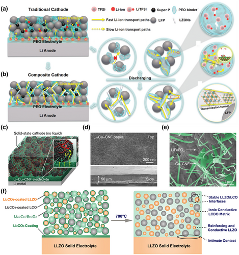
In addition to co-mingled electrolyte particles, low-melting-point ionic conductors can also be mixed in with the cathode materials. The cathode is prepared at a temperature higher than the melting point of the ionic conductor, subsequently cooling it to ensure a uniform distribution in the cathode. This method can prevent the interfacial side reactions while preventing cathode particle fragmentation. For example, Han et al. effectively reduced the negative effect caused by poor interfacial contact between the cathode and electrolyte, as well as the isolation of the interfacial reactions, by adding low-melting-point Li2.3C0.7B0.3O3 at the interface of LiCoO2 and LLZO. Although the interfacial performance between the cathode and electrolyte were effectively improved, the approach came at a higher cost (Figure 7f).[131]
5.2 Artificial Protective Layer and Cathode Particle Coating
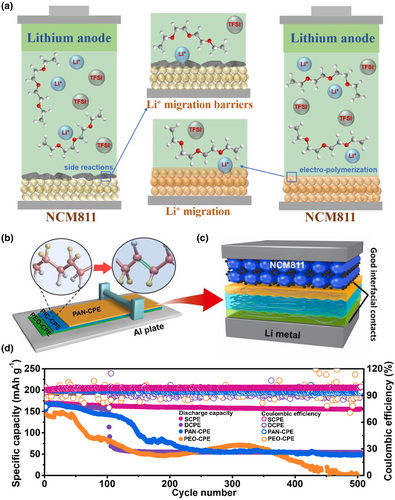
The cathode interface protective layer should have excellent anti-oxidation capability, a wide electrochemical window, high ionic conductivity, low electronic conductivity, and good wettability. For example, Li et al. constructed a new high-pressure fluorinated polymer interface with good durability by in-situ solvent-free electropolymerization between a LiNi0.8Mn0.1Co0.1O2 (NCM811) cathode and a PEO-based solid polymer electrolyte (Figure 8a).[132] A close physical contact at the interface was achieved, which significantly suppressed space charge effects, improved interfacial stability, and prevented electrochemical oxidative decomposition of the PEO polymer electrolyte. The in-situ formation of a poly(fluoroalkyl acrylate) polyfluoroalkyl acrylate-based interfacial layer promoted Li+ migration and improved ionic conductivity. Zhou et al.[107] prepared a poly(N-methylmalonamide) (PMA) interfacial layer inserted between a PEO-substrate SSE diaphragm and LiCoO2 to prevent the electrolyte from being oxidized by a high-voltage cathode. Li et al.[133] used antioxidant polyacrylonitrile (PAN)-polymer electrolyte (CPE) in contact with a solid electrolyte composed of NCM811 and polyvinylidene fluoride (PVDF)-CPE filled with 80 wt% Li3xLa2/3-xTiO3 (LLTO) nanofibres to improve the electrochemical stability of the interface (Figure 8b–d).
Coating the cathode particles with a high-voltage stable lithium-ion conductor can effectively inhibit the volume change of the cathode during charging and discharging cycles. The coating can also isolate the generation of interfacial byproducts at the same time. Common coating methods include sol–gel, spraying, screen printing, spin coating, pulsed laser deposition (PLD), and atomic layer deposition (ALD) techniques. The first four of these are mainly mixed by mechanical means and are prone to induce uneven coating, while PLD and ALD are more uniform but at an increased cost. The use of LiNbO3 cladding on LiCoO2 as a buffer layer between electrolyte and cathode material can significantly reduce the cathode interface resistance and enhance the high multiplicity performance of solid-state lithium batteries.[77, 134] Okada et al. prepared LiNi1/3Mn1/3Co1/3O2 powders coated with LiAlO2 by the sol–gel method combined with ultrasonication, which could effectively suppress the increase in interfacial resistance between LiNi1/3Mn1/3Co1/3O2 electrode material and the sulfide-based solid electrolyte Li3PS4.[135] Takada et al. used LiTaO3 as a cladding layer material, which exhibited high ionic conductivity in the amorphous state and formed at low temperatures to avoid thermal diffusion of the elements.[136]
5.3 3D Porous Electrolyte Loaded with Cathode Particles and all-in-One Electrodes
An integrated electrode is a strategy in which the electrolyte is prepared together with the lithium anode during preparation, with close contact at the cathode/electrolyte interface and low impedance, effectively preventing dendrite growth. For example, Lin et al. developed a novel integrated cathode/thin solid electrolyte with only 17 μm thick. The electrolyte exhibited enhanced mechanical strength to inhibit lithium dendrites, and enhanced the cathode/electrolyte interface bonding by preparing the solid electrolyte directly on the cathode, significantly reducing the interfacial resistance (Figure 9a).[137] The solid electrolyte can fill the holes inside the cathode during curing, providing a continuous ion transport path, and allowing the use of highly loaded cathodes. The all-solid-state battery using LiFePO4 cathode could reach a capacity of 155.2 mAh g−1 at 45 °C after 500 cycles, with a capacity retention of 84.3% and a discharge capacity of 124.1 mAh g−1 even at a high cathode loading mass of 13 mg cm−2. Besides, Chen et al. developed a microwave-assisted ultrafast sintering technique for preparing various ceramic electrolytes via a domestic microwave oven in the air.[139] Due to its ultrafast sintering process, the electrolyte not only effectively suppressed the volatilization of Li but also enabled ultrafast co-sintering of the integrated electrode-electrolyte. The resulting electrode/electrolyte interface was very compact and achieved high capacity through suppressed elemental inter-diffusion.
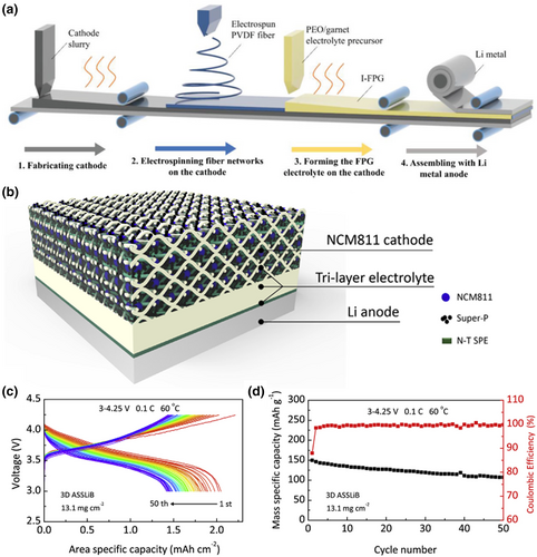
Loading cathode particles in an electrolyte with a three-dimensional porous structure can effectively increase the contact area between the electrolyte and the cathode, solving the problem of poor interfacial contact and suppressing the volume change of the cathode particles. The commonly used preparation methods are flow-delayed and templating, among which the templating method is a simple process with a lower cost. For example, Zhang et al.[138] proposed a 3D interpenetrating structure prepared by a simple template casting method, containing a NCM811 cathode to increase energy density and mitigate interfacial incompatibility. The porous layer provided mechanical support and acted as a highly loaded body for the NCM811 materials, while the dense layer separated the electrodes to achieve high energy density and improved interfacial compatibility (Figure 9b–d).
6 Electrolyte Design to Mitigate Electrolyte/Electrode Interfacial Issues
Interface problems between the solid electrolyte and the electrodes can be solved by rational design of the electrolyte. A decreased weight of SSE will increase the energy density. The preparation of thinner SSE can significantly increase the energy density of the battery. However, since the SSE becomes thinner, its mechanical strength is poor, which makes it more likely to be pierced by Li dendrites.[72] Interface problems can be affected not only by physical properties but also by chemical properties, as the cathode in a battery is usually more oxidized and the lithium anode is more reduced. Therefore, the electrolyte should be highly resistant to oxidation on the side in contact with the cathode and to reduction on the side near the anode, and have high chemical stability at both high and low temperatures. The electrolyte should also have a high mechanical strength and ionic conductivity to inhibit the growth of lithium dendrites. To achieve these requirements, the structure of the electrolyte can be modulated to achieve a stable interfacial contact.
6.1 Multi-Layered and Gradient Structure
The Janus structure of electrolytes is achieved by regulating the function of each layer so as to own oxidation resistance at the cathode interface and reduction resistance at the anode interface. This is important to avoid the electrolyte film from being oxidized or reduced, which can lead to the formation of stable anode/cathode–electrolyte interface and SEI films, effectively improving the mechanical strength of the electrolyte. For example, Arrese-Igor et al. prepared a composited bilayer polymer electrolyte of poly(propylene carbonate) (PPC) and PEO, allowing PEO to contact the lithium metal due to its relatively good resistance to reduction and PPC to contact the cathode due to its relatively good resistance to oxidation, thus improving the life of the battery (Figure 10a).[140] Hu et al. proposed an electrolyte with a Janus structure, the main body of which consisted of plastic crystal electrolyte (PCE), while a PEO component was added to one side of the electrolyte. The Janus structure was good at avoiding contact between Li1.3Al0.3Ti1.7(PO4)3 (LATP) particles/succinonitrile (SN) molecules and the lithium anode, effectively improving the stability of the electrolyte. Meanwhile, it reduced the lithium/electrolyte interfacial impedance (Figure 10b).[141] Wu et al.[142] designed Janus electrospun PAN nanofibres electrolyte that simultaneously enhanced the interface wettability between the lithium metal anode and the sulfur cathode. Ultrathin covalent triazine piperazine (CTP) nanomembranes with microporous structures were modified on the PAN membrane surface by in-situ interfacial polymerization. The fast ion conductor LLZTO was designed by coiled magnetron sputtering at the interface between the PAN membrane and the anode (Figure 10c). CTP-PAN-LLZTO exhibited remarkably low overpotential even after cycling for 200 and 600 h at a current density of 1 mA cm−2, and the voltage polarization remained as low as 11.7 mV even after cycling for 1200 h at a current density of 2 mA cm−2.
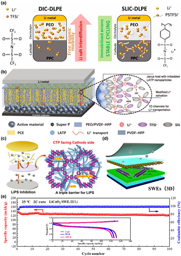
In addition to the Janus structure, SSE with a sandwich structure is also a good choice to stabilize the interface. The two upward and downward sides of this structure have anti-oxidation and anti-reduction properties, respectively, which can ensure the stability of the interface between SSE and the anode and cathode electrodes. The middle layer improves the mechanical strength and enhances the ionic conductivity of SSE. For example, Li et al. proposed a modified sandwich structure consisting of PVDF/LLTO-PEO/PVDF to achieve high ionic conductivity and high electrochemical stability as a polymer-based composite electrolyte by preventing the reaction between LLTO and lithium metal through the PVDF skin layer and inhibiting the growth of lithium dendrites. The LLTO-PEO intermediate layer reduced the bulk resistance and improved the electrochemical stability of the electrolyte (Figure 10d,e).[143]
Gradient structure involves intentionally altering the concentration of substances in an electrolyte within an electrolyte at different locations to create a concentration gradient. The gradient structure exhibits a difference in the performance on each side of the electrolyte, enhancing its effectiveness when getting in touch with the anode and cathode. For example, Sheng et al. introduced a viable buffer layer consisting of LiI and PEO (PEO-LiI) between Li and Li4SnS4 (LSS) by a self-diffusion method.[144] The PEO-LiI layer contributes to the electronic segregation of the LiI-rich SEI and the voids between the grain boundaries in the bulk electrolyte, purposefully stabilizing the interface and bulk grain boundaries of LSS. Thanks to the enhanced interfacial ion conduction and the suppression of electron conduction in the bulk phase, the cells can be cycled stably for more than 1500 h.
6.2 Inorganic–Organic Electrolyte Blending
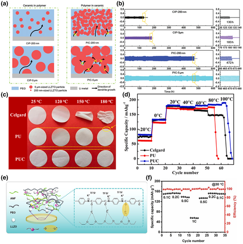
Mixing inorganic particles into organic electrolytes can take the advantages of both components. The addition of inorganic particles can effectively increase the amorphous region of polymer electrolytes and increase the number of chains transporting Li+. At the same time, some particles themselves have higher Li+ conductivity, which provides more options for the transport of Li+. The combination not only provides high conductivity for fast ion transport, but also provides good adhesion to tight interfaces and flexibility to accommodate interface fluctuations. Additionally, the inorganic particles can enhance the mechanical strength of the electrolyte, inhibiting dendrite growth and reducing the occurrence of side reactions at the interface. Overall, this approach is relatively straightforward to implement, but the underlying reactions may be complex and require thorough investigation. For example, Huo et al. designed a sandwich-type composite electrolyte with a mechanically strong “polymer-in-ceramic” sandwich and a flexible “ceramic-in-polymer” outer layer. This sandwich-type composite electrolyte with multistage garnet particles was successfully achieved with dendrite suppression and good interfacial contact with the electrode (Figure 11a,b).[145] The “polymer-in-ceramic” interlayer with 80 vol% 5 μm LLZTO showed a high mechanical strength of 12.9 MPa and hindered the propagation of Li dendrites through physical barriers. The outer layer of the “ceramic-in-polymer” outer layer with 20 vol% 200 nm LLZTO particles provides a smooth and flexible surface with a high Li-ion transfer number of 0.47. Du et al. prepared a layered, self-assembled MOF network of polyimide polymer electrolytes followed by permeation with poly(vinylidene fluoride) polymer electrolytes.[148] This continuous linear pathway improved the mechanical strength of the solid electrolyte, effectively preventing the growth of lithium dendrites as well as interfacial damage. The electrolyte exhibited a high ionic conductivity of 4.08 × 10⁻⁴ S cm−1 at 30 °C, and the prepared LiFeO4//Li full cell maintained 96% capacity after 500 cycles at room temperature. Cheng et al. electrostatically spun polyurethane nanofibers filled with Al2O3 material as an electrolyte.[146] The electrolyte had excellent thermal stability at 211 °C, superior mechanical properties with no significant shrinkage at higher temperatures, and good liquid absorption properties, as well as a large pore size and high ionic conductivity (Figure 11c,d). Yin et al.[147] constructed a new solid-state electrolyte with a 3D backbone of aramid nanofibers (ANFs) and PEO, filled with LLZO particles and lithium bis(trifluoromethyl)amide (LiTFSI) as the lithium salt (Figure 11e,f). The 3D cross-linked structure of ANFs and PEO effectively disrupted the orderliness of PEO chains, reduced crystallinity, and provided new ion transport pathways, significantly enhancing the toughness and hardness of the electrolyte. The recent advances in the performance of organic–inorganic hybrid solid-state electrolyte are summarized in Table 1.
| Inorganic filler | Polymer host | Ionic conductivity/S cm−1 | Temperature/°C | Specific capacity/mAh·g−1 | References |
|---|---|---|---|---|---|
| Li1.5Al0.5Ge1.5(PO4)3 | PEO | 1.67 × 10⁻⁴ | RT | 148.7/0.2C | [31] |
| Li0.3La0.557TiO3 | PEO | 1.8 × 10⁻⁴ | 25 | – | [149] |
| SiO2 | PEO | 6.31 × 10⁻⁶ | 25 | 143/0.5C | [150] |
| Li2SO4-SiO2 | PEO | 3.9 × 10⁻⁵ | RT | 120/0.5C | [151] |
| Li0.33La0.557TiO3 | PEO | 2.3 × 10⁻⁴ | RT | – | [152] |
| Li6PS5Cl | PEO | 2.83 × 10⁻⁴ | 40 | 125.2/1C | [153] |
| Li6.4La3Zr1.4Ta0.6O12 | PEO | 1.15 × 10⁻⁴ | 30 | 147.3/0.2C | [154] |
| Li1.5Al0.5Ge1.5(PO4)3 | PEO | 1.25 × 10⁻⁴ | 25 | 148.5/0.5C | [155] |
| Li10SnP2S12 | PEO | 1.69 × 10⁻⁴ | 50 | – | [156] |
| Li6.28La3Zr2Al0.24O12 | PEO | 8.5 × 10⁻⁵ | 25 | – | [157] |
| SiO2 | PEO | 1.3 × 10⁻⁴ | 30 | 159/0.5C | [158] |
| Li0.3La0.557TiO3 | PEO | 5.53 × 10⁻⁵ | RT | 137/0.1C | [159] |
| Li0.33La0.557TiO3 | PEO | 2.4 × 10⁻⁴ | RT | – | [160] |
| Li0.3La0.557TiO3 | PEO | 1.6 × 10⁻⁴ | 24 | 135/2C | [37] |
| SiO2-Li2SO4 | PEO | 1.3 × 10⁻⁴ | 60 | 80/2C | [151] |
| BaTiO3 | PEO | 1.8 × 10⁻⁶ | 25 | – | [161] |
| Li0.3La0.557TiO3 | PEO/PPC | 5.66 × 10⁻⁵ | RT | 135/0.5C | [162] |
| Li6.75La3Zr1.75Ta0.25O12 | PEO/SN/PTFE | 1.2 × 10⁻⁴ | RT | 158/0.1C | [163] |
| Li7La3Zr2O12 | PAN | 1.6 × 10⁻³ | RT | 110/average | [164] |
| Li0.3La0.557TiO3 | PAN | 2.4 × 10⁻⁴ | RT | – | [165] |
| Li7La3Zr2O12 | PAN | 1.31 × 10⁻⁴ | 20 | – | [166] |
| Li0.3La0.557TiO3 | PAN | 6.05 × 10⁻⁴ | 30 | – | [167] |
| Li1.3Al0.3Ti1.7(PO4)3 | PAN/PEO | 6.5 × 10⁻⁴ | 60 | 144/0.2C | [168] |
| Li7La3Zr2O12 | PVDF | 1.16 × 10⁻⁴ | 30 | 213/0.2C | [169] |
| Li0.35La0.55TiO3 | PVDF | 5.3 × 10⁻⁴ | 25 | – | [170] |
| ZSM-5 | PVDF | 1.7 × 10⁻³ | 25 | 140/0.5 C | [171] |
| Li7La3Zr2O12 | PVDF-HFP | 9.5 × 10⁻⁴ | 20 | 140/0.2C | [172] |
| Li7La3Zr2O12 | PVDF-HFP | 1.2 × 10⁻⁶ | 25 | 120/0.5C | [173] |
| Li10SnP2S12 | PVCA | 2.0 × 10⁻⁴ | 25 | 130/0.5C | [174] |
| Si/ Li6.28La3Zr2Al0.24O12 | PEDGA | 4.9 × 10⁻⁴ | RT | 147/0.5C | [175] |
| Li1.3Al0.3Ti1.7(PO4)3 | PDMS/PEGDA | 2.4 × 10⁻⁶ | 25 | – | [176] |
| SiO2 | PEGPEA | 2.16 × 10⁻⁵ | RT | 135/0.4C | [177] |
| Li1.3Al0.3Ti1.7(PO4)3 | PIL | 7.78 × 10⁻⁵ | 30 | 138.4/1C | [178] |
| La2Zr2O7 | PVP | 1.2 × 10⁻⁴ | RT | 165.6/0.5C | [179] |
| Li6.5La3Zr1.5Ta0.5O12 | PVP | 1.0 × 10⁻³ | RT | – | [180] |
| Li6PS5Cl | PDA | 2.0 × 10⁻⁴ | 25 | – | [181] |
| Li3OCl0.5Br0.5 | NBR | 2.6 × 10⁻⁵ | RT | 137/0.1C | [182] |
| Li6PS5Cl | CEL | 6.3 × 10⁻³ | 25 | 148/0.1C | [183] |
- CEL, cellulose; NBR, butadiene acrylonitrile rubber; PAN, polyacrylonitrile; PDA, polydopamine; PDMS, polydimethylsiloxane; PEC, poly(ethylene carbonate); PEGDA, poly(ethylene glycol) diacrylate; PEGPEA, poly(ethylene glycol ether acrylate); PEO, polyethylene oxide; PIL, poly ionic liquid; PTFE, polytetrafluoroethylene; PVCA, poly(vinyl chloride-acetate); PVDF, poly(vinylidene fluoride); PVDF-HFP, poly(vinylidene fluoride-co-hexafluoropropylene); PVP, polyvinyl pyrrolidone.
6.3 3D Skeleton with Low Tortuosity and Enhanced Mechanical Properties
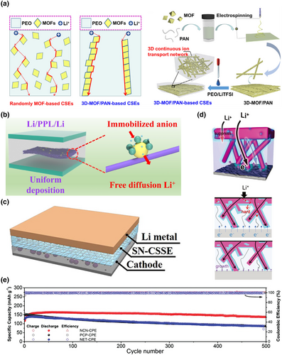
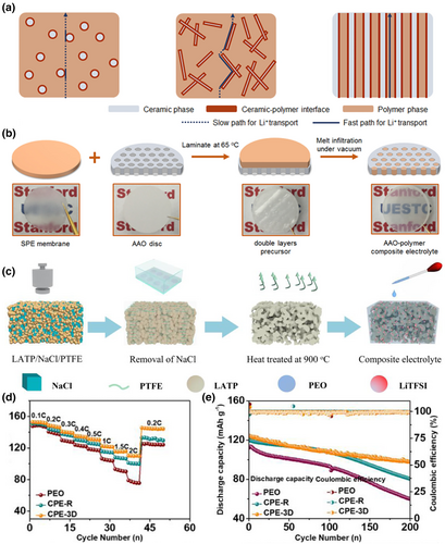
The Li+ ion channels on the microscopic surface of common solid-state electrolytes are mostly transverse structures, and this structure makes Li+ ions more curved during electrolyte migration and increases resistance. In order to improve the ion transport speed in solid-state electrolytes, the channels of Li+ ions can be made into 3D structures with low tortuosity, so that Li+ ions can be transported rapidly along the vertical direction in solid-state electrolytes.[184, 185] The unique structure design improved the ion conductivity, and enabled uniform deposition of Li ions at the cathode and anode. And a 3D skeleton can improve the mechanical strength of SSE and effectively prevent the growth of lithium dendrite. The preparation of organic or inorganic 3D skeletal reinforced electrolytes is the most common way to produce low-bending electrolytes, among which electrospinning is one of the main means for preparing 3D skeletons. When combined with other material fabrication techniques, such as chemical vapor deposition and hydrothermal treatment, electrospinning enables powerful synthetic strategies to tailor the structural and compositional characteristics of energy storage materials.[162, 163] For example, Li et al. constructed a 3D interconnected metal–organic framework (MOF) network by electrospinning and then backfilled it with polymer/lithium salt to make a composite solid electrolyte (CSE) based on the interconnected MOFS network, which provided a continuous pathway for rapid Li+ migration between MOF particles, thus effectively improving the ionic conductivity. Meanwhile, the electrolyte significantly improved the mechanical properties of the resulting CSE due to the reinforcement of the 3D network strength and promoted the uniform deposition of Li ions (Figure 12a).[186] Zhang et al.[187] constructed a PAN/LLZTO 3D network structure framework by electrospinning and then casting PEO/LiTFSI slurry onto the nanofiber film to produce a composite electrolyte, which reduced the crystallinity of the PEO polymer, thus successfully constructing a continuous Li+ transport channel and improving the mechanical strength of the PEO matrix, obtaining good interfacial compatibility (Figure 12b). The reversible capacity of the prepared full cell after 1000 cycles at a current density of 1.0 C was 120.7 mAh g−1. Zha et al.[188] used (PVDF-HFP) fibrous membranes prepared by electrospinning as a mechanically reinforced framework to improve the mechanical properties. The interfacial reaction can be mitigated by the formation of SN-Li+ association in the concentrated electrolyte, effectively reducing the proportion of free SN molecules and inhibiting the reactivity of SN toward the lithium metal cathode (Figure 12c). Fan et al.[189] reported a corrugated 3D nanowire-block ceramic nanowire (NCN) backbone-enhanced composite electrolyte with the advantage of regulated interfacial Li+ transport (Figure 12d). The assembled all-solid-state batteries exhibited superior cycling stability with 90.2% capacity retention after 500 cycles (Figure 12e).
In addition to the preparation of 3D frameworks by electrospinning, 3D frameworks can also be prepared by the physical method or the chemical synthesis method.[190] The 3D framework prepared by the physical method can obtain a more perfect Li+ channel with low curvature. Thereby inhibiting the growth of dendrites and accelerating the transport of Li+. For example, Zhang et al.[191] demonstrated an anodized aluminum oxide (AAO)-polymer composite electrolyte with vertical arrangement and continuous ceramic-polymer interface by filling solid polymer electrolytes into the nanochannels of alumina (Figure 13a,b). The electrolyte has a continuous and rich interfacial ion conduction path directly bridging the cathode and anode, and its ionic conductivity is as high as 5.82 × 10⁻⁴ S cm−1 at room temperature. Most of the 3D frameworks prepared by chemical synthesis have the ability to transport Li+, and the prepared electrolytes will have higher ionic conductivity. Liu et al. proposed an enhanced backbone strategy to form a stable CEI scaffold and avoid the continuous decomposition of polycarbonate by introducing high-pressure-resistant cationic COF material into polycarbonate, which had a high resistance to oxidation. After the introduction of COF into solid polycarbonate electrolytes (C-SPE), the stable COF can act as a reliable scaffold to prevent CEI collapse and continuous decomposition of the polycarbonate and inhibit side reactions at the electrode/electrolyte interface.[192] A high Li+ conductivity of 1.3 × 10⁻⁴ S cm−1 at 25 °C and a Li+ transfer number of up to 0.62 were achieved. Wang et al. developed a 3D LATP porous conductive framework by using common NaCl powder as a sacrificial template, which can provide a continuous Li+ conductive pathway and sufficient mechanical modulus to facilitate rapid Li+ transport and prevent Li dendrite growth (Figure 13c).[193] Li/Li-symmetric cells prepared with this electrolyte exhibited high stability in excess of 1000 h at a current density of 0.2 mA cm−2 (Figure 13d, e). Zuo et al.[194] synthesized a novel chemically stable hybrid network electrolyte by ring-opening polymerization of lipoic acid (TA) with poly(ethylene glycol) diacrylate. The initiator-free crosslinking process reduced the occurrence of interfacial side reactions and improved the interfacial stability between the electrolyte and lithium metal. The ionic conductivity of the electrolyte reached 1.1 × 10⁻⁴ S cm −1 at room temperature.
7 Summary and Perspective
- The interface between the electrolyte and the lithium anode often exhibits weak contact, which can lead to uneven deposition of lithium ions and cause a series of issues, such as localized voltage increase and dendrite formation. By preparing an interfacial layer with high ionic conductivity, low thickness, excellent stability, and certain mechanical strength, this problem can be effectively addressed.
- It is necessary to improve the interface compatibility between the electrolyte and the cathode to reduce interface impedance. Coating the cathode particles with a stable lithium-ion conductor can effectively decrease the interface impedance, suppress the volume change of the cathode, and reduce interface reactions.
- The inherent low ionic conductivity of solid-state electrolytes can lead to electrolyte polarization, which severely deteriorates electrochemical performance. Additionally, further improvements are needed in solid-state electrolytes to prevent penetration by lithium dendrite growth, which can cause short circuits in lithium batteries. One common choice is to incorporate a 3D scaffold into the electrolyte, which can simultaneously enhance the mechanical strength and ionic conductivity of the electrolyte.
- Electrochemical stability needs to be enhanced by improving the antioxidant and antireduction properties of the electrolyte, reducing the interface reactions between the electrolyte and the cathode/anode electrode, and improving interface stability further. The preparation of a multi-layered structure electrolyte is the most promising strategy to achieve this goal. These multi-layered structures can provide a stable interfacial barrier that prevents detrimental reactions between the electrolyte and electrodes, thereby improving the overall electrochemical stability of the battery.
- The transport behavior mechanism of lithium ions at the interface has not been fully elucidated. It is crucial to clarify the ion transport behavior at the interface and explore various specific mechanisms to enhance interface properties. Therefore, the development of more advanced characterization and a combination of simulation techniques is needed to help address these issues.
Notwithstanding the aforementioned hurdles, solid-state electrolytes have garnered significant attention as a pivotal avenue for enhancing the safety and overall performance of lithium batteries. Augmenting the efficacy of the interface between the electrolyte and both the cathode and anode electrodes constitutes a crucial aspect in expediently realizing practical applications for solid-state batteries. We hope this review can elucidate the enduring challenges and future trajectories in the realm of solid-state electrolyte development.
Acknowledgments
H.H. and L.W. contributed equally to this work. This work was supported by the National Key R & D Program (2022YFE0206400), the National Natural Science Foundation of China (52202256), the Natural Science Foundation of Jiangsu Province of China (BK20220612), the Science and Technology Development Fund, Macao SAR (0096/2020/A2, 0013/2021/AMJ, and 0082/2022/A2), and the Opening Project of the Key Laboratory of Jiangsu Province for Silk Engineering, Soochow University (KJS2277). We also acknowledge the funds from Jiangsu University “Qinglan Project” and the Young Elite Scientists Sponsorship Program of the Jiangsu Association for Science and Technology.
Conflict of Interest
The authors declare no conflict of interest.


