In Situ-Constructed LixMoS2 with Highly Exposed Interface Boosting High-Loading and Long-Life Cathode for All-Solid-State Li–S Batteries
Abstract
As the persistent concerns regarding sluggish reaction kinetics and insufficient conductivities of sulfur cathodes in all-solid-state Li–S batteries (ASSLSBs), numerous carbon additives and solid-state electrolytes (SSEs) have been incorporated into the cathode to facilitate ion/electron pathways around sulfur. However, this has resulted in a reduced capacity and decomposition of SSEs. Therefore, it is worth exploring neotype sulfur hosts with electronic/ionic conductivity in the cathode. Herein, we present a hybrid cathode composed of few-layered S/MoS2/C nanosheets (<5 layers) that exhibits high-loading and long-life performance without the need of additional carbon additives in advanced ASSLSBs. The multifunctional MoS2/C host exposes the abundant surface for intimate contacting sites, in situ-formed LixMoS2 during discharging as mixed ion/electron conductive network improves the S/Li2S conversion, and contributes extra capacity for the part of active materials. With a high active material content (S + MoS2/C) of 60 wt% in the S/MoS2/C/Li6PS5Cl cathode composite (the carbon content is only ~3.97 wt%), the S/MoS2/C electrode delivers excellent electrochemical performance, with a high reversible discharge capacity of 980.3 mAh g−1 (588.2 mAh g−1 based on the whole cathode weight) after 100 cycles at 100 mA g−1. The stable cycling performance is observed over 3500 cycles with a Coulombic efficiency of 98.5% at 600 mA g−1, while a high areal capacity of 10.4 mAh cm−2 is achieved with active material loading of 12.8 mg cm−2.
1 Introduction
Energy density and safety issues are the main concerns in developing lithium-ion batteries (LIBs) to meet ever-growing demands for electric vehicles (EVs) and grid energy storage. However, the gravimetric energy densities of state-of-the-art LIBs based on intercalating cathodes/anodes with low specific capacities have evolved to approach the theoretical limit (~280 Wh kg−1).[1, 2] An appealing way to further elevate the energy density is switching from conventional intercalation chemistry to conversion one.[3] Lithium–sulfur (Li–S) batteries, as one of the most intriguing examples, can potentially achieve revolutionary energy densities due to the conversion chemistry of Li with S that has a far higher theoretical capacity (1675 mAh g−1) and energy density (2600 Wh kg−1).[4, 5] Meanwhile, sulfur is earth-abundant, cheap, and environmentally innocuous. Generally, S and its discharge product Li2S are both ionic/electronic insulators, and thus most Li–S batteries strongly rely on the dissolution of lithium polysulfide intermediates in ether-based liquid electrolytes and re-precipitation somewhere else as solid phases.[1, 6] However, a notorious issue brought by this is that polysulfides might freely diffuse to the anode (called the “shuttle effect”), causing poor Coulombic efficiency (CE), severe self-discharging, and fast capacity fading.[7] Over the past decade, various remediation concepts have been proposed, including physical confinement, chemical absorption, catalytic conversion, and interfacial engineering.[8] Regrettably, the battery performance still deteriorates seriously under high-loading and lean-electrolyte conditions owing to the indispensability and inevitability of polysulfide dissolution in liquid Li–S systems.[9]
A way out of the tough dilemma is replacing liquid electrolytes with solid-state electrolytes (SSEs). In particular, all-solid-state Li–S batteries (ASSLSBs) based on sulfide SSEs can physically eliminate the polysulfide shuttling and simultaneously reduce security risks associated with volatile and flammable solvents in liquid electrolyte batteries.[9, 10] Recent years have witnessed the burgeoning of ASSLSBs through employing highly mechanical-ductile and ion-conducting sulfide SSEs (e.g., Li6PS5Cl, Li10GeP2S12, and Li2S-P2S5 glasses).[6] Owing to the lack of kinetics-favorable polysulfide dissolving, the solid-phase conversion of insulating S/Li2S is strongly limited by the electron and ion transport at the triple-phase interfaces between active materials, SSEs, and electron conductive additives.[6] In this regard, it is usually necessary to mix a high fraction of nanocarbon additives and SSEs to obtain composite sulfur cathodes with nanoscaled homogeneity by intense ball milling or solution processing. As a result, a high interfacial contact area between SSEs and carbons would also be formed, which poses a non-negligible oxidative decomposition of SSEs during battery charging, eventually leading to increased internal resistance and limited cycle life of battery cells.[6]
One of the most appealing strategies to solve the puzzle is employing transition metal sulfides (TMSs) as alternative sulfur hosts because of their superior interfacial compatibility and stability with sulfide SSEs.[11-15] Moreover, most TMSs are also electrochemically active within the working voltage window of the S/Li2S redox couple, indicating a dual intercalation–conversion mechanism involved and resulting extra capacity contributed. Among various TMSs, layered transition metal disulfides (TMDs, e.g., MoS2, TiS2, WS2, and VS2)[12, 13, 16-19] are particularly interesting for energy storage due to their graphite-like layered structure, in which the metal atoms are octahedrally coordinated with sulfur atoms to form 2D S-M-S layers bonded together by weak van der Waals interactions. Such a unique layered structure can endow these TMDs or their lithiation forms with mixed ionic-electronic conductivity, which can help minimize the use of SSE degradation-promoted carbon additives and simultaneously facilitate Li+ migration in electrodes. As a pioneered work, Nazar et al have employed flower-like VS2 aggregates comprised of ~100 nm thick VS2 plates as sulfur hosts.[14] Benefiting from fast 2D Li+ transport channels, metallic conductivity, and additional capacity contribution of VS2, the S/VS2 hybrid cathode-based ASSLSBs have achieved a high sulfur utilization of ~85% and a high areal capacity of 7.8 mAh cm−2. However, the specific surface areas of the pristine TMDs are still relatively lower than those of nanocarbon-based sulfur hosts (e.g., carbon black, graphene, CNTs, and porous carbons), which may limit their electronic/ionic contact with active S/Li2S and SSEs, resulting in inadequate sulfur utilization and power capability.[20-23] It is well-known that layered TMDs can be thinned from bulks to few-layered nanosheets or even monolayers with large aspect ratios and specific surface areas (using top-down methods, such as mechanical and chemical exfoliation, and bottom-up strategies, such as wet chemical synthesis and chemical vapor deposition),[24-27] which is highly desired for their applications in SSEs due to prominently extended interfacial contact with other electrode components. TMD nanosheets have been extensively investigated in various liquid electrolyte battery systems, where the electrochemical storage in the electrode involves intercalation and conversion reaction mechanisms.[28-30] It exhibits theoretically good rate capability and cycling stability, because the weak van der Waals interaction between the structural layers can facilitate the reversible Li+ intercalation and extraction without significant volume change, and also prevents the pulverization of active materials caused by the repeated lithiation and delithiation process.[31] However, the few-layered TMD nanosheets have not yet been explored as advanced sulfur host materials applied in ASSLSBs.
Here, we report an ultrathin S/MoS2/C nanosheet hybrid as a high-loading and long-life cathode for ASSLSBs. The sulfur host material is composed of crumpled few-layered MoS2 nanosheets (<5 layers) with interlayer-intercalated carbon and surface-attached CNTs (named MoS2/C for simplification), which is synthesized via a hydrothermal-annealing method reported previously by us.[32] Then, a sulfur layer is coated onto the MoS2 nanosheets by a vapor deposition approach, yielding an ultrathin S/MoS2/C hybrid cathode material. Such a structural design owns multi-merits required by ASSLSBs: 1) highly exposed MoS2 surfaces allow intimate area-to-area contacts between active materials (S/Li2S), host material (MoS2/C), and sulfide SSE (Li6PS5Cl); 2) lithiated MoS2 (LixMoS2) is a mixed ion-electron conductor, establishing low-tortuous carrier transport pathways to activate S/Li2S redox while minimizing the use of the carbon additive in the S/MoS2/C/Li6PS5Cl cathode composite (only ~3.97 wt%); 3) MoS2 can have extra contribution to capacity. With a high active material loading (S + MoS2/C) of 60 wt% in the cathode composite, the assembled solid cells deliver superior electrochemical performances.
2 Results and Discussion
2.1 Materials Characterization
The preparation procedures of the S/MoS2/C composite are presented in Figure 1a. The sulfur host material (MoS2/C) has been prepared based on a hydrothermal-annealing method, using Na2MoO4/thiourea as MoS2 precursors and oxidized CNTs/glucose as carbon sources.[32] In the synthesis, CNTs act as heterogeneous nucleation sites and inhibitors to impede vertical stacking of S-Mo-S layers and induce their lateral growth, while glucose molecules can intercalate between adjacent MoS2 monolayers and reduce surface energy.[33] As a result, the ultrathin MoS2 nanosheets with less than five stacked layers could be attained, which could be spontaneously crumpled into a paper ball-like shape during the hydrothermal reaction. The subsequent annealing in Ar results in the complete carbonization of oxidized CNTs and glucose, endowing the MoS2/C composite with good electronic conductivity. With these unique structural characteristics, the MoS2/C composite features robust mechanical elasticity and anti-aggregation ability. Sulfur has been loaded onto MoS2/C by a vapor deposition method, and the saturated sulfur content in the resultant S/MoS2/C composite is ~32.3 wt% determined by TG analysis (Figure 1b).
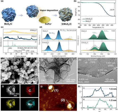
Spectroscopy characterizations clarify materials' chemical compositions. The XRD pattern of S/MoS2/C is shown in Figure 1c, with elemental S powder and MoS2/C as references. The MoS2/C host exhibits a few weak diffraction peaks indexed to the few-layered 2H-MoS2 phase, similar to the reported result.[32] It is worth noting that the (002) diffraction peak of the 2H-MoS2 phase is significantly broadened, related to the coexistence of non-expanded and carbon-intercalated MoS2.[34] Upon sulfur deposition, all those peaks become almost invisible, and strong reflection signals associated with crystalline S element also disappear. This result suggests that the sulfur deposited onto the MoS2/C surface is highly dispersed without bulky sulfur residue in S/MoS2/C.[35] Besides, no detectable reflections assigned to CNTs or pyrolyzed carbon are found in the XRD patterns of MoS2/C and S/MoS2/C, probably attributed to their low content (9.78 and 6.62 wt% in MoS2/C and S/MoS2/C, see Table S1, Supporting Information). Raman spectra (Figure S1, Supporting Information) confirm the presence of carbon components in both samples as characteristic D- and G-band peaks emerge around 1336 and 1580 cm−1, respectively.[36, 37] Other sharp Raman peaks centered at 377 and 402 cm−1 are associated with in-plane () and out-plane (A1g) vibrations of S atoms in MoS2, respectively.[36] Further, nitrogen physisorption analyses (Figure S2, Supporting Information) reveal that MoS2/C features highly exposed surfaces with a specific surface area of 109 m2 g−1, significantly reduced to 34 m2 g−1 for S/MoS2/C upon sulfur loading. XPS is a surface sensitive technique employed to identify the surface chemical state and composition of MoS2/C and S/MoS2/C. As shown in Figure S3, Supporting Information, the XPS survey spectra demonstrate that both MoS2/C and S/MoS2/C consist of C, Mo, and S elements. In the high-resolution Mo 3d & S 2s spectrum of MoS2/C (Figure 1d), the component peaks centered at 233.3 and 230.1 eV correspond to Mo 3d3/2 and Mo 3d5/2 of Mo4+, respectively; another broad peak located at 227.3 eV is characteristic of S 2s. The S 2p spectrum of MoS2/C (Figure 1e) displays two dominant peaks at 164.1 and 162.9 eV relating to S 2p1/2 and S 2p2/3 of S2−, respectively. As for S/MoS2/C, all those peaks associated with Mo 3d, S 2s, and S 2p prominently shift toward lower binding energy, which can be attributed to the interaction between MoS2 and elemental S after sulfur loading. Meanwhile, new doublet peaks at 165.2 and 164.1 eV can be deconvoluted in the S 2p spectrum of S/MoS2/C, which is derived from the elemental S. The above spectroscopy results confirm the sulfur deposition in S/MoS2/C.
The structure of MoS2/C and S/MoS2/C samples can be observed by SEM and TEM in detail. As shown in Figure 1f, the S/MoS2/C composite exhibits a spherical shape with a diameter ranging from 200 to 300 nm, accompanied by some surface ridges and folds (Figure 1g). Furthermore, the internal carbon nanotubes (indicated by white arrows) within the S/MoS2/C particle are observable. These CNTs are wrapped in thin layers, providing a highly conductive pathway for electrons through the interparticle interfaces of the S/MoS2/C, which also can contribute to avoiding their direct contact with SSEs, thus reducing the decomposition of SSEs. The high-resolution TEM image of the S/MoS2/C composite is presented in Figure 1h, revealing nanolayers that are less than five layers in thickness. Notably, two sets of lattice fringes with interplanar distances measuring 0.626 and 1.021 nm can be discerned. The lattice fringe exhibiting interplanar distances of 0.626 nm is attributed to the (002) plane of 2H-MoS2, while the broader interlayer spacing (1.021 nm) is a result of carbon intercalation derived from glucose, which facilitates electron/ion transfer.[29, 38-40] The lattice fringes with d-spacings of 0.227 and 0.272 nm also correspond to the (103) and (100) planes of 2H-MoS2.[34] The aforementioned results are in accordance with the XRD findings of host material MoS2/C. The TEM images of the MoS2/C host are also shown in Figure S4, Supporting Information. The structural changes before and after sulfur loading are not discernible. For the S/MoS2/C composite, the mappings reveal that C, Mo, and S elements are evenly dispersed across the whole composite. It is hard to distinguish between sulfur from MoS2/S host because of the same morphology and chemical composition. The possible reason is that electron beam irradiation triggers the sublimation of sulfur in an ultra-high-vacuum environment during TEM measurement. Fortunately, the presence of sulfur has been confirmed by TG and XPS analysis. Furthermore, AFM has been used to measure the thickness of the monolayer of S/MoS2/C pieces after they were deliberately broken with ultrasonic technique (Figure 1j). AFM analysis suggests that the thickness of the S/MoS2/C layer is <2 nm. This is clear evidence to prove that the S/MoS2/C layer is thin.
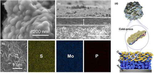
The cathode is prepared by mechanically milling the S/MoS2/C composite and Li6PS5Cl powders in a 6:4 mass ratio, without any additional carbon additives. Based on the low carbon content (6.62 wt%) in the S/MoS2/C composite, the use of the carbon additive is greatly reduced in the S/MoS2/C/Li6PS5Cl cathode composite (only ~3.97 wt%). As shown in Figure 2a, cathode composite powder shows ball-like nanoscaled particles and homogeneity uniform dispersion with Li6PS5Cl. Further cold pressing by 360 MPa for 3 min, the layer construction was obtained (Figure 2b). The cross-sectional SEM image of the cathode layer shows a thickness of 42 μm in ASSLSBs. To get a more detailed view (Figure 2c), it can be found that the S/MoS2/C are distributed uniformly with squashed morphology in the cathode layer. In addition, the elemental mappings of the cathode are shown, where S, Mo, and P are evenly distributed throughout the cathode, with much less content of P (Figure S5, Supporting Information), suggesting the Li6PS5Cl content is less common in the cathode, and the S/MoS2/C is the main part of the cathode. For the visual description in Figure 2d, a high interfacial contact area between Li6PS5Cl and S/MoS2/C would be formed after ball milling. Further cold pressing during the ASSLSBs assembling, the S/MoS2/C composites are changed from ball-like nanoparticles to nanosheets, which is favorable to establish the closer area-to-area contact between the active material and Li6PS5Cl and low-tortuous carrier transport pathways for ion/electron during (dis)charging in the inner cathode layer. This construction is beneficial to the subsequent electrochemical performance.
2.2 Reaction Mechanism and Interface Evolution of ASSLSBs during Cycling
The cyclic voltammogram profiles of the as-synthesized S/MoS2/C cathode are displayed in Figure 3. The onset potential of the S/MoS2/C (Figure 3a) and MoS2/C (Figure 3b) start at ~1.6 and ~1.1 V versus Li+/Li-In, respectively. It's possibly caused by the sulfur component in the S/MoS2/C cathode. For the S/MoS2/C cathode (Figure 3a), two distinct peaks are observed at ~1.3 and ~0.4 V versus Li+/Li-In during cathodic curves. The peak at ~1.3 V versus Li+/Li-In is attributed to the conversion of sulfur (S) into lithium sulfide (Li2S), which is consistent with the position of the reduction peak for S as depicted in Figure 3b.[31] The peak observed at ~0.4 V versus Li+/Li-In can be attributed to the insertion of lithium ions into the MoS2 interlayer, leading to the formation of LixMoS2. This observation is consistent with the lithiation process of the MoS2/C cathode sample, as indicated by the peak position.[41] In the anodic curves, an oxidation peak is observed, which may be attributed to the proximity of the potential oxidation peak for Li2S and that of the delithiation process for LixMoS2. Therefore, it is reasonable to assign the primary oxidation peak at ~2.2 V versus Li+/Li-In to the charging reactions involving delithiation of LixMoS2 to MoS2 and the conversion of Li2S to S.[12, 14]
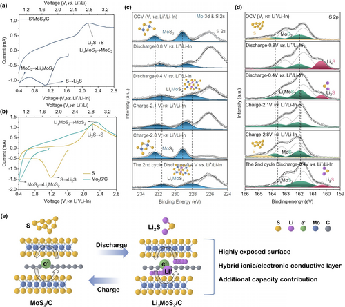
Overall, the MoS2/C exhibits an electronic conductivity, while the lithiation product (LixMoS2/C) is a mixed ion/electron conductor, combining Li6PS5Cl (ionic conductor) and S (active material) to form the intimate nanosized triple-phase boundaries. The sufficient triple-phase interface makes a great contribution to the excellent electrochemical performance.
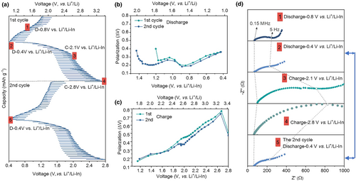
The GITT technique is employed to investigate the evolution of the cathode internal interface during cycling (Figure 4a). The cell is subjected to a series of current pulses, each followed by a 3-h relaxation period. The sulfur composite cathode exhibits a pair of plateaus at ~1.1 and ~2.2 V during the discharge/charge process, which is consistent with the CV curves. The electrode always undergoes an activation process during the first lithiation, resulting in a different appearance of the first sweep compared to subsequent ones (Figure 4a).[13, 44, 45] Furthermore, the voltage polarization (ΔV) of each current pulse is determined by analyzing the relaxation curve presented in Figure 4b,c. The ΔV represents the combined effect of the iR drop and relaxation process. The iR drop is attributed to the ohmic resistance at the interface between the sulfur composite and Li6PS5Cl, while the relaxation process involves Li+ concentration reaching an equilibrium state.[46] During discharging, the ΔV initially exhibits an increasing trend after reaching 0.8 V versus Li+/Li-In, whereas during charging, the ΔV shows an initial increase followed by a decrease. Generally, the value of ΔV in the 2nd cycle is slightly lower than that in the 1st cycle, which can be attributed to electrode activation. Ex situ EIS spectra were acquired during the cycling process. The overall impedance exhibits an increase gradually, which is consistent with the polarization plots obtained through GITT. During the discharge process, the semicircular response in the mid-frequency range expands toward lower frequencies. During the charging process, the semicircle feature expands sequentially toward lower frequencies, while the straight lines in the low-frequency region are progressively suppressed at 2.1 V versus Li+/Li-In or even vanish at 2.8 V versus Li+/Li-In. As marked by the blue arrow in Figure 4d, the phenomenon occurs in the second cycle. The impedance spectra at 0.4 V versus Li+/Li-In between two consecutive cycles remain almost unchanged, implying the reversibility of the electrode reaction.
2.3 Theoretical Calculations
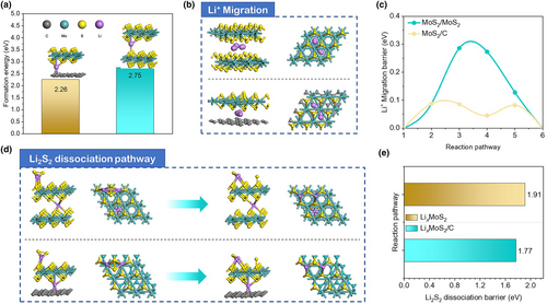
To understand the distinctive electrochemical performance of the MoS2/C host in the sulfur cathode, density functional theory (DFT) calculation is conducted to elucidate its unique mechanisms. The host models of MoS2/MoS2 and MoS2/C are depicted in Figures S6 and S7, Supporting Information. Due to the presence of a sulfur coating on the surface of MoS2/C, we exclusively consider the hollow site of MoS2 as the preferred formation site for LixMoS2. The MoS2/C and MoS2/MoS2 bilayer system serves as a simplified model for the subsequent calculations.[32] As depicted in Figure 5a, the MoS2/MoS2 bilayer system has a LixMoS2 formation energy of 2.75 eV. In comparison, the MoS2/C bilayer system has a lower LixMoS2 formation energy of 2.26 eV, which renders a faster reaction kinetics between lithium and MoS2/C. The migration of Li+ is a crucial factor in evaluating the performance of batteries, as it accompanies both the charging and discharging processes. The migration pathway of lithium in MoS2/MoS2 and MoS2/C bilayer systems is subsequently investigated (Figure 5b). The migration of lithium is simulated as it moves from one favorable adsorption site to another, while the barrier is calculated (Figure 5c). The lithium migration barrier in MoS2/MoS2 is 0.286 eV, which is significantly higher than that in the MoS2/C bilayer, 0.0875 eV. This indicates that the migration rate of Li atoms is faster in the latter. For ultrathin S/MoS2/C, the maximized exposed surface facilitates direct areal-to-areal contacting with Li6PS5Cl and low-tortuous carrier transport pathways for ion/electron in the inner cathode layer. Additionally, it is also interesting to study the lithium process occurring on the exterior surface of the sulfur coating. For the conversion process from sulfur to Li2S in the ASSLSBs, the electrochemical redox reactions are conversions between the sulfur and Li2S with an intermediate phase of Li2S2 formation.[47] In fact, the conversion from Li2S2 to Li2S is a rate-limiting step.[40] Therefore, the transition from Li2S2 to Li2S is utilized as a simplified model for calculating sulfur dissociation. The dissociation pathway of Li2S2 on the LixMoS2 and LixMoS2/C surfaces with lithium interaction and energy barrier is shown in Figure 5d,e, respectively. The dissociation energy barrier of Li2S2 calculated for MoS2/C with lithium interaction is 1.77 eV, which is lower than that of MoS2/MoS2 (1.91 eV) with lithium interaction, indicating superior performance in activating sulfur during the discharging process.
2.4 Electrochemical Performance
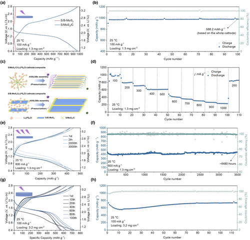
It is essential to investigate the electrochemical performance of ASSLSB with dual active components (S + MoS2/C) at room temperature. Figure 6a illustrates the discharge–charge profiles of S/MoS2/C and S/B-MoS2 cathodes during the 2nd cycle at 100 mA g−1 with active loading of 1.3 mg cm−2. In the second cycle, a discharge capacity of 968.3 mAh g−1 is observed from the S/MoS2/C cathode. The capacity is gradually increased and then stabilized during cycling, which is 980.3 mAh g−1 at the 100th cycle (Figure 6b). This corresponds to a high reversible discharge capacity of 588.2 mAh g−1 based on the whole cathode weight. In comparison, the discharge capacity in the second cycle for the S/B-MoS2 cathode is only ~35 mAh g−1. It is evident that the nanostructure of the sulfur host plays a crucial role in determining its capacity. The SEM image, as shown in Figure S8, Supporting Information, reveals the structure of B-MoS2 with a 100 nm-thick solid morphology. Furthermore, the analysis of nitrogen adsorption–desorption isotherm is presented in Figure S9, Supporting Information. The B-MoS2 material exhibits a low specific surface area of 10.55 m2 g−1, indicating unfavorable conditions for sulfur loading and insufficient triple-phase contact. After the introduction of sulfur, the TG test (Figure S10, Supporting Information) confirms a sulfur content of 4.8% in the S/B-MoS2 composite. However, this low level of sulfur is insufficient to achieve high capacity for the S/B-MoS2 cathode. To aid the understanding of the concept, the schematic diagram is presented in Figure 6c. The point-to-point contact between the active material and solid electrolyte in ASSLSB is not as efficient as a liquid electrolyte which has superior mobility.[14, 48] The challenge is to design an interface between the active material and solid electrolyte to ensure sufficient ion and electron supply.[49] Many studies have already concluded that the sufficient triple-phase interface is heavily related to the particle size and morphology of the electrode materials.[50-54] Thus, the nano-engineered electrode material is vital for better electrochemical performance. The structure of the S/MoS2/C composite transfers from a ball-like few-layer structure to a nanosheet under pressure after the solid-state battery assembly. The nanosheet structure with interpolated distribution between S/MoS2/C and solid electrolyte possesses the bigger total interface contact area between the active material and solid electrolyte acting as the fast “highways” for ions and electrons thus a better electronic/ionic conductivity. On the contrary, the thick massive structure of S/B-MoS2 composite with low sulfur content is not conductive because of the long transport distance in the inner structure of active material, the more tortuous ionic/electronic pathways, and the limited interfacial contact area between the active material and solid electrolyte. Overall, the thin layer structure of S/MoS2/C supports a sufficient triple-phase interface for faster kinetics and full solid chemical reaction, which provides a firm foundation for better electrochemical performances. Therefore, it is reasonable to choose the few-layered structure as a sulfur host. The rate performance of the S/MoS2/C cathode with active loading of 1.3 mg cm−2 is displayed in Figure 6d. It shows the discharge capacity of 984.3, 801.9, 720.3, 623.6, 612.8, 424.7, 367.4314.8, 280.1, and 242.0 mA h g−1 at the current density of 100, 200, 300, 400, 500, 600, 700, 800, 900, and 1000 mA g−1, respectively. When the rate returns to 200 mA g−1, the reversible capacity recovers to 619.7 mA h g−1, demonstrating good tolerance to reduplicative rate change. The discharge–charge profiles of the S/MoS2/C cathode at higher current density (600 mA g−1) are shown in Figure 6e. It is a normal phenomenon that the polarization decreases with the increasing cycle numbers indicating an activation process occurred.[42] The cycling performance and Coulombic efficiency are recorded in Figure 6f. The S/MoS2/C cathode displays stable cycling performance with high Coulombic efficiency approaching 98.5% and retains a discharge capacity of 448.5 mA h g−1 after 3500 cycles. The discharge–charge profiles of the S/MoS2/C cathode at a current density of 100 mA g−1 with high active mass loading of 3.2 mg cm−2 are also shown in Figure 6g. The S/MoS2/C cathode shows discharge capacities of 733.1, 560.4, 574.0, 632.8, 696.0, and 734.1 mA h g−1 at the 1st, 10th, 20th, 40th, 60th, 80th, and 100th cycle, respectively. The discharge capacity is also decreased first and then increased after 10 cycles (Figure 6h). It is because of the activation progress with high active loading at room temperature. It is reasonable to believe that the excellent behavior of the S/MoS2/C cathode at room temperature is aided by the few-layered nanostructure with highly exposed surfaces and in situ-formed LixMoS2 as mixed ion-electron conductor during discharging. The highly exposed few-layered surfaces and conductive LixMoS2 provide a necessary condition for low-tortuous carrier transport pathways to activate S/Li2S redox.
It is very useful to investigate the electrochemical performance of S/MoS2/C cathode with higher active mass loading at 60 °C. The representative discharge–charge profiles and cycling performance curves of the S/MoS2/C cathode with active loading of 6.2 mg cm−2 (Figure 7a,b), 8.0 mg cm−2 (Figure 7c,d), and 12.8 mg cm−2 (Figure 7e,f) are presented, respectively. The cathode with active material loading of 6.2 mg cm−2 delivers a similar first three reversible discharge capacities of ~1153 mAh g−1. The cathode with active loading of 8.0 mg cm−2 delivers a reversible discharge capacity of 887.9 mAh g−1 at the first cycle and a similar reversible discharge capacity of 1005.8 mAh g−1 at the second and third cycles. The cathode with active loading of 12.8 mg cm−2 delivers a reversible discharge capacity of 426.1 mAh g−1 at the first cycle, 754.5 mAh g−1 at the second cycle, and 870.0 mAh g−1 at the third cycle, respectively. The activation stage gradually evolved with the increased active material loading. As we all know, the polarization between discharge and charge plateaus is associated with the reaction's kinetics and electrochemical activity. The polarization increases with the increased active loading on the first cycle. In general, it is a normal phenomenon because of the increased transmission resistance. This increased active loading can be attributed to the lengthened electronic/ionic pathways in thick electrodes.[14] The cathodes with active loading of 6.2, 8.0, and 12.8 mg cm−2 display cycling performances with 98.9% Coulombic efficiency, and retain a discharge capacity of 1042.7 mAh g−1 after 65 cycles, 896.9 mAh g−1 after 65 cycles, and 839.4 mAh g−1 after 16 cycles, respectively. Generally, the S/MoS2/C cathode in ASSLSBs has achieved a high active loading of 12.8 mg cm−2 and an areal capacity as high as 10.4 mAh cm−2. The thickness of the cathode is 30, 51.8, 58.2, 89.0, and 123.0 μm, respectively (Figure S11, Supporting Information). Energy density calculations (gravimetric and volumetric) based on these measurements are provided in Table S2, Supporting Information. The cathode is measured in a mold cell with a stack pressure of 0.5 tons, so the volume is calculated from the thickness and cell area. The calculation equations are given in SI. The area capacity of the cathode and the minimizing electrolyte layer thickness are the key determinants of energy density. The SEM characterization of ASSLSBs with 12.8 mg cm−2 active loading after failure is performed (Figure S12, Supporting Information). At the initial state, the surface and cross-section of the cathode show a smooth state, and there is no obvious delamination between it and the electrolyte layer. After failure, the surface of the cathode shows obvious cracking and delamination. Volume changes during the cycling of the cathode at high active loading lead to cracking and delamination, resulting in poor ion/electron transport and ASSLSBs failure. Finally, the cycle performance of the ASSLSBs that utilize Li as the anode is shown in Figure 7g. Such ASSLSB delivers an average reversible discharge of 924.8 mAh g−1 and can retain 23 cycles.
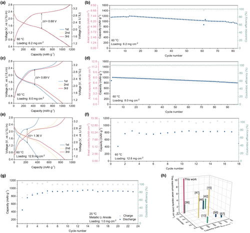
With no additional carbon and a high percentage of active materials in the cathode, this work shows an excellent electrochemical performance in comparison with recently published works. Figure 7 summarizes the capacities based on the total weight of the cathode, maximum areal capacities, and the related cycle numbers in the recently published papers.[13, 15, 36, 42, 46, 47, 56, 57] The areal capacity is the highest in our work. The achieved capacity based on the total weight of the cathode with the corresponding cycling numbers also matches some of the recent results in ASSLSBs studies.[36] The impressive performance of the S/MoS2/C cathode in ASSLSBs can be attributed to (i) the highly exposed MoS2 surfaces with intimate area-to-area contact for better electronic/ionic conducting, (ii) the conversion & intercalation cathode for encompassing both lithium intercalation and metallic electronic conductivity, (iii) the in situ-formed LixMoS2 during discharging for establishing low-tortuous carrier transport pathways.
3 Conclusions
In summary, the S/MoS2/C samples have been prepared by self-assembly assisted hydrothermal-annealing method and vapor deposition approach, resulting in uniform distribution and tight contact between MoS2/C and S. The S/MoS2/C samples exhibit the few-layered (<5 layers) structure and act both as the sulfur host and active material in the cathode. Subsequently, the intimate area-to-area contacts between active materials (S + MoS2/C) and SSE are maintained to ensure the low-tortuous carrier transport pathways, the lithiated MoS2 (LixMoS2) with the mixed ion-electron conductor is in situ formed during cycling to feed ion/electron to activate S/Li2S redox and extra capacity contribution. Thus, active S/MoS2/C (the carbon content in active materials is ~6.62 wt%) content can be as high as 60 wt% in the cathode (the carbon content in the cathode is ~3.97 wt%) without extra carbon additive. The carbon content of the cathode composite is lower than that of commercial LIB cathode (5 wt%). Moreover, the ASSLSBs with S/MoS2/C cathode display long-life cycling performance over 3500 cycles and an areal capacity up to 10.4 mAh cm−2 with 12.8 mg cm−2 active loadings (much higher than that of LIB (3.5 mAh cm−2). It provides a viable way to enhance the ionic/electronic conductivity of the cathode. This approach offers a new avenue for the development of next-generation energy storage systems with high energy density and enhanced safety.
4 Experimental Section
Preparation of active materials
The MoS2/C composite was synthesized by procedures reported recently by our lab.[32] Briefly, oxidized multiwalled CNTs (15 mg) were dispersed in sodium dodecylbenzene sulfonate solution (75 mL; 0.2 wt%). Then, the above suspension (25 mL) was mixed with deionized water (45 mL), sodium molybdate (151 mg), thiourea (200 mg), and glucose (125 mg) by rigorously stirring for 30 min. The obtained mixture was placed in a Teflon-lined stainless steel autoclave and kept at 250 °C for 24 h. After cooling down, the precipitation was harvested by filtration, followed by drying at 60 °C and annealing at 700 °C for 3 h in Ar to obtain the MoS2/C product. For comparison, bulk MoS2 (B-MoS2) was purchased from Alfa Aesar.
The S/MoS2/C composite was prepared by a vapor deposition method. In short, elemental S and MoS2/C powders with a mass ratio of 2:1 were vacuum-sealed in a fused silica tube and heated at 300 °C for 12 h. The S/MoS2/C composite was obtained after cooling down. For comparison, the S/B-MoS2 composite was prepared by the same procedure above.
Materials characterization
Scanning electron microscopy (SEM) and transmission electron microscopy (TEM) images were taken by a Carl Zeiss ultra plus microscope and a JEOL JEM-2100F microscope equipped with a dispersive energy X-ray (EDS) spectrometer, respectively. Atomic force microscopy (AFM) imaging was performed on a Bruker Fastscan instrument. Carbon content in the as-synthesized composite was analyzed by an elemental analyzer (Vario EL cube). Nitrogen sorption isotherm data were measured on a Micromeritics ASAP 2020M analyzer. Thermogravimetric (TG) curves were collected on a NETZSCH STA449F3 analyzer in Ar with a temperature ramping rate of 10 °C min−1. X-ray diffraction (XRD) patterns were recorded on an X'Pert Pro diffractometer with Cu Kα radiation (λ = 0.15418 nm). Raman spectra were obtained by a RENISHAW inVia spectrometer. X-ray photoelectron spectroscopy (XPS) data were collected on the LESCALAB 250 Xi instrument.
Preparation of ASSLSBs
Firstly, a cathode composite was prepared by mixing the active materials (S/MoS2/C or S/B-MoS2) and Li6PS5Cl with a mass ratio of 6:4 without any extra carbon additives. Then, Li6PS5Cl powder (100 mg) as the SSE layer was placed in a polytetrafluoroethylene mold (inner diameter of 10 mm) and cold pressed at 240 MPa. Afterward, a given amount of cathode composite powder was placed on the other side of the Li6PS5Cl layer and pressed at 360 MPa, and Li-In alloy foil (contains 4 mg Li powders) was placed on another side of the Li6PS5Cl layer and pressed at 120 MPa. Finally, an initial stack pressure of 60 MPa was applied to the cells by a mechanical jig fixture. The thickness of Li6PS5Cl and Li-In layers are 600 and 100 μm in various tests.
For the ASSLSBs utilizing Li as the anode assembled by the same procedure above, the amount of Li is 0.8 mg equivalent to the active mass loading of 1 mg cm−2.
Electrochemical measurements
Galvanostatic discharge–charge tests and galvanostatic intermittent titration technique (GITT) studies were conducted on a Land CT 2001A battery test system with a voltage window of 0.4–2.8 V versus Li+/Li-In. For GITT tests, the cells were operated using a pulse current of 100 μA g−1 for 30 min, followed by a 3 h relaxation at each step. Cyclic voltammogram (CV) tests were performed on a CHI660E electrochemical workstation at a scan rate of 0.05 mV s−1 with a voltage window of 0.4–2.8 V versus Li+/Li-In. Electrochemical impedance spectroscopy (EIS) data were collected on an Autolab PGSTAT302N electrochemical workstation with an oscillation amplitude of 10 mV in frequencies ranging from 1 MHz to 0.1 Hz.
DFT calculations
All the density functional theory (DFT) calculations were carried out using the Vienna ab initio simulation package (VASP). The Perdew–Burke–Ernzerbof (PBE) functional within the generalized gradient approximation (GGA) was chosen to describe the exchange-correlation function.[56-60] Blöchl's all-electron-like projector augmented wave (PAW) pseudo-potential was used to describe the core-valence electron interaction.[61] The valence electronic states were expanded in plane wave basis sets with a kinetic cutoff energy of 400 eV, while a 3 × 3 × 1 Monkhost-Pack k-point grid was applied.[61] The convergence tolerance of total energy calculation was carried out at 1.0 × 10⁻⁵ eV/atom with an ionic force minimization level of 0.01 eV/Å. The models of two layers and 4 × 4 supercells of MoS2 (001) and MoS2 (001)/C were built for the simulation. A vacuum layer as large as 20 Å was used along the c direction normal to the surface to avoid periodic interactions. During the structure optimization, all the atoms were allowed to be relaxed. To search the transition states (TSs) of Li migration and Li2S2 dissociation, the climbing image nudged elastic band (CI-NEB) method was applied.[62]
Acknowledgements
The authors are grateful to the financial support from the National Natural Science Foundation of China (T2241003), the National Key Research and Development Program of China (2022YFB4003500), and the Key R&D project of Hubei Province, China (2021AAA006).
Conflict of Interest
The authors declare no conflict of interest.


