Lowering Sodium-Storage Lattice Strains of Layered Oxide Cathodes by Pushing Charge Transfer on Anions
Abstract
Due to a high energy density, layered transition-metal oxides have gained much attention as the promising sodium-ion batteries cathodes. However, they readily suffer from multiple phase transitions during the Na extraction process, resulting in large lattice strains which are the origin of cycled-structure degradations. Here, we demonstrate that the Na-storage lattice strains of layered oxides can be reduced by pushing charge transfer on anions (O2−). Specifically, the designed O3-type Ru-based model compound, which shows an increased charge transfer on anions, displays retarded O3–P3–O1 multiple phase transitions and obviously reduced lattice strains upon cycling as directly revealed by a combination of ex situ X-ray absorption spectroscopy, in situ X-ray diffraction and geometric phase analysis. Meanwhile, the stable Na-storage lattice structure leads to a superior cycling stability with an excellent capacity retention of 84% and ultralow voltage decay of 0.2 mV/cycle after 300 cycles. More broadly, our work highlights an intrinsically structure-regulation strategy to enable a stable cycling structure of layered oxides meanwhile increasing the materials' redox activity and Na-diffusion kinetics.
1 Introduction
Cathode materials largely determine energy density of sodium-ion batteries (SIBs), which is a promising candidate for large-scale energy storage applications.[1-4] Among all the SIBs cathodes, layered transition-metal (TM) oxides (NaxTMO2, 0 < x ≤ 1) have attracted increasing attention because of their relatively higher energy density.[5, 6] According to the coordination of Na+ to neighboring oxygen ions, NaxTMO2 can be categorized into O- and P-type phase structures. The symbols of “O” and “P” refer to a prismatic and octahedral coordination environment respectively. The formation of O- or P-type structures is highly dependent on the Na contents in NaxTMO2. For instance, the NaxTMO2 prefers to show an O-type structure with a relatively small Na slab spacing, while there is usually a P-type structure with a relatively large Na slab spacing in Na-deficient NaxTMO2 (x < 1) to accommodate an increased Coulombic repulsion between negatively charged TMO2 slabs.[7-9] During the cycling process accompanied by Na+ extraction and insertion, phase transitions between O- and P-types commonly occurred in NaxTMO2. In addition, a change in stacking sequence of TMO2 slabs during cycling, leading to more complex phase transitions such as P3–O1, is also widely reported.[10, 11] The numerical 1 or 3 indicates the repeated TMO2 slabs in one cell unit. The phase transitions can cause large lattice strains, which have been considered as a main origin of cycled-structure collapse and degraded electrochemical properties (e.g., capacity loss and voltage decay).[12, 13]
To retard the phase transitions and lower the lattice strains of NaxTMO2, substitution of heterogeneous elements is a popular approach. For instance, introducing appropriate metal elements such as Zn, Al, and Ti into the TM layer has been demonstrated effective in suppressing the irreversible phase transitions and adverse TMO2 slabs slipping[14-16]; meanwhile, doping elements such as K and Mg into the Na layer have been reported to play a pinning role in tuning the repulsion between negatively charged TMO2 slabs and stabilizing the layered structure framework.[17-19] However, the substitution of these electrochemical-inactive elements can reduce the materials' redox activity and is not favorable for the achievement of high capacity. Particularly, the introduction of extra elements into the Na layer will hinder the Na-ion diffusion, limiting the cathodes' power density.[20, 21] In this regard, an ideal modification strategy should not only suppress the detrimental phase transitions but also avoid the adverse effects described above. It has been well demonstrated that the phase transitions of layered oxide cathodes originate from the increased interlayer O–O repulsion accompanied by the extraction of Na ions.[22, 23] Specifically, at highly de-sodiation state, the adjacent TMO2 layers will glide to balance the strong O–O repulsion, resulting in the phase transitions (top panel of Scheme 1). Since the interlayer O–O Coulomb repulsion is closely associated with the negative charge carried by oxygen ions,[24] it can be theoretically reduced through pushing charge transfer on anions (O2−) during the Na extraction process (bottom panel of Scheme 1). Meanwhile, the charge transfer on anions can increase the cathode's energy density and rate capability due to the triggered anionic redox activity and reduced Na–O attraction respectively.[11, 25, 26]
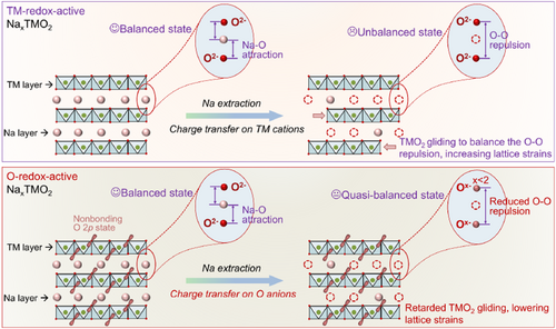
To verify the effectiveness of the above modification concept, a Ru-based layered oxide was selected as the model compound because the strong Ru–O bonding can exclude the possible irreversible anionic redox process.[13, 27] The thus designed Na[Li1/4Ni1/3Ru5/12]O2 compound with increased charge transfer on anions during the Na extraction process shows a retarded multiple phase transitions and reduced lattice strains as directly revealed by in situ X-ray diffraction and geometric phase analysis. Meanwhile, an increased rate capability and long-cycle capacity/voltage retention are also observed due to the reduced Na-diffusion resistance and stable Na-storage structure. Our work not only reports a versatile structure-regulation strategy to intrinsically lower the lattice strains, but also highlights the role of anionic redox, a recently proposed important charge compensation mechanism, in stabilizing the cycling structure of layered oxide cathodes.
2 Results and Discussion
For the Ru-based layered oxide Na[Ni2/3Ru1/3]O2 (denoted as NNR), it has been reported that there is an anionic redox activity (i.e., charge transfer on anions) due to the redox coupling process between Ru and O ions.[31] To further trigger the anionic redox activity and increase the charge transfer on oxygen anions during the Na extraction process, we designed a Li-substituted Na[Li1/4Ni1/3Ru5/12]O2 (denoted as NLNR) compound. As supported by DFT calculations, compared with the NNR compound, the NLNR shows an expectedly increased anionic redox activity. Specifically, as the partial density of states (PDOS) results shown in Figure 1a,b, due to the non-bonding O 2p states, a much larger PDOS between 0 and −2.5 eV (closer to the Fermi level) is found in the NLNR.[32] Moreover, a greater PDOS originating from the nickel states was observed for NNR, whereas NLNR possesses a much smaller PDOS between 0 and −2.5 eV at different de-sodiation states. The above results showed that the NLNR possesses higher redox activity of oxygen anion.
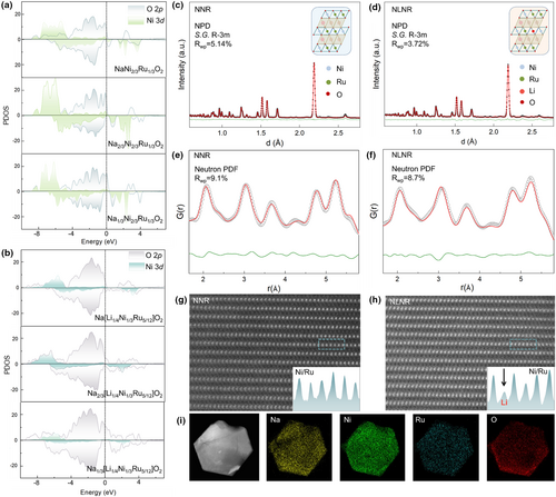
In addition, as revealed by XRD and HRTEM results, the prepared NNR and NLNR samples show pure phase and good crystallinity (Figures S1 and S2, Supporting Information). Since neutrons can differentiate light elements (e.g., Na, Li) more readily,[33] NPD and neutron PDF were used to quantify the average and local crystal structure respectively (Figure 1c–f, Tables S1–S4, Supporting Information). The refinement results of NPD and local neutron PDF data indicate that there is Li doping into the TM layer of the NLNR sample, which is consistent with our theoretical design. Furthermore, HAADF-STEM were employed to study the atomic structure of the NNR and NLNR samples. Owing to the intensity of atom columns is proportional to the averaged atom number of elements, the fact that no observable contrast in TM slab was found in Figure 1g, while showing significant reduction in Figure 1h, further demonstrates that the Li element has been successfully introduced into the TM layer. Furthermore, TEM elemental energy-dispersive spectroscopy (EDS) mapping was utilized to reveal the elements' distribution in the designed NLNR cathode material, and the results show that Na, Ni, Ru, and O elements are uniformly distributed on the particle (Figure 1i).
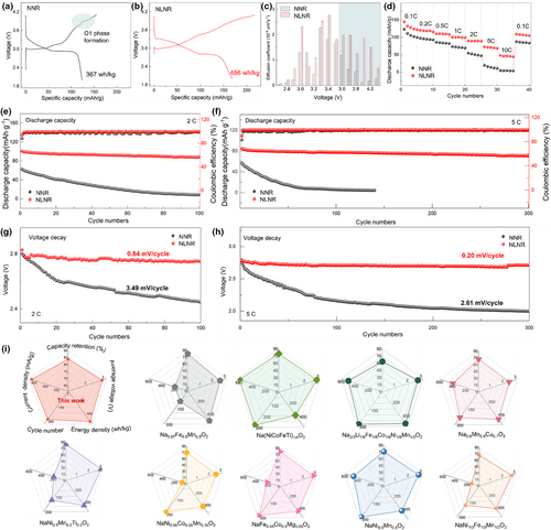
As expected, the NLNR cathode shows an enhanced specific capacity due to its triggered anionic redox activity. It can be seen in Figure 2a,b that the NNR and NLNR cathodes deliver a discharge capacity of 144 mAh−1 g−1 (367 Wh kg−1) and 168 mAh g−1 (486 Wh kg−1) respectively. Also, it should be noted that there is a distinct voltage plateau observed at around 3.9 V, which is closely correlated with possible phase transitions during the Na extraction process. In contrast, the NLNR cathode shows smoother charge–voltage curves, suggesting the retarded phase transitions during the Na extraction process. More details regarding this phenomenon will be discussed later. In addition, the charge transfer on anions reduces the Na–O attraction and lowers Na-ion diffusion barrier, favoring the Na-ion diffusion coefficients as calculated based on the PITT results (Figure 2c). The enhanced Na-ion diffusion leads to a superior rate capability of the NLNR cathode (Figure 2d). Specifically, the NLNR can still show a discharge capacity of 73 mAh g−1 at 5 C, while the capacity of the NNR cathode drops to only 20 mAh g−1. Furthermore, we conducted long-cycling performance tests on the NNR and NLNR cathodes at 2 C and 5 C respectively, and it is worth noting that the cycle stability of the NLNR is improved remarkably. Specifically, the NLNR retained a capacity retention rate of around 87% after 100 cycles accompanied by a voltage decay of 0.84 mV/cycle at 2 C, whereas NNR only exhibited a capacity retention of around 14% accompanied by a voltage decay of 3.49 mV/cycle (Figure 2e,g). Furthermore, when the current density was increased to 5 C, as shown in Figure 2f,h, the NNR cathode experiences rapid capacity fading with an ultralow capacity retention of 1.7% and the voltage decay is 2.61 mV per cycle after 140 cycles. As a comparison, the NLNR exhibits a superior cycling stability with an excellent capacity retention of around 84% and ultralow voltage decay of 0.20 mV per cycle after 300 cycles, thus guarantee delivering higher energy density consistently (Figure S4, Supporting Information). Furthermore, to assess the electrochemical performance more comprehensively, the radar charts including five key metrics are depicted in Figure 2i. Compared with the recently reported layered cathodes for sodium-ion batteries, our designed NLNR shows an optimal overall performance such as an excellent long-cycling stability, the highest working voltage, and energy density. These findings provide new insight for designing high-performance layered cathodes with triggered anionic redox activity and also open a new perspective for facilitating practical application in future SIBs.
Ex situ hard X-ray absorption spectroscopy (hXAS) and soft X-ray absorption spectroscopy (sXAS) measurements were conducted to investigate the charge transfer processes in the NNR and NLNR cathodes. For the NNR sample, Ni K-edge shifts to a higher energy, indicating that most of the initial charge capacity comes from the oxidation of Ni2+ (Figure 3a). For the NLNR sample, there is a slight evolution in its Ni K-edge XANES data during the charging process (Figure 3b). This observation indicates that there is only a small amount of Ni2+ ions involved in the charge compensation process during charging, and the oxidation of lattice oxygen contributes to the most of initial charge capacity.[34] The higher anionic redox activity of the NLNR cathode was further confirmed by the ex situ sXAS results. The O K-edge sXAS for the pristine, 4.1 V-charged, and 2.0 V-discharged states was collected in both total electron yield (TEY, Figure 3c,d) mode and total fluorescence yield (TFY, Figure 3e,f) mode.[35] TEY is sensitive to the surface electronic structure, and TFY is sensitive to the bulk electronic structure. The pre-edge feature around 530 eV is related to the O 1s to the TM-O unoccupied hybridized states, which is associated with the changes in the density of empty states juts above the Fermi level that is commonly strengthened as electrons/sodium atoms are extracted (i.e., charging). In TEY mode of Figure 3d, when Na is extracted from the lattice, the pre-edge intensity at 528.5 eV exhibits obvious increase. These phenomena signify the feature that the creation of stable electron holes lying just above the Fermi energy and this process is accompanied by a much smaller amount of Ni2+ and a large number of oxygen ions involved in the redox reaction. And when recovered to the initial state during the subsequent discharge to 2.0 V, an opposite evolution process of the pre-edge peak is observed, suggesting that there is reversible charge compensation provided by Ni2+/Ni3+ and anionic redox.[36] In contrast, the sXAS spectra in Figure 3c show a much lower intensity and negligible changes in the pre-edge intensity for NNR, implying the small contribution of anionic redox.
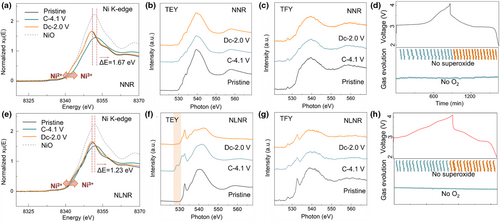
To exclude the influence of possible irreversible anionic redox on the electrochemical properties, in situ Raman and operando DEMS measurements were performed to investigate the redox process. Obviously, no superoxide-related O2− stretching vibration located at around 1100 cm−1 can be observed for the NNR and NLNR cathodes (Figure 3g,h). Owning to the highly covalent Ru–O bond and high Na/Ru ratio existing in Ru-based layered oxides, which would enable a stable layered structure upon charging without the formation of O–O dimer.[37, 38] Notably, there was no evolution of O2 gas for the NNR (Figure 3g), indicating that the redox coupling process between Ru and O ions dominates the activity of anionic redox, and confirming that the suitability of selected model compound. Although there is a higher anionic redox activity in the NLNR, the release of O2 has also not been detected (Figure 3h), which provides more direct evidence for the stable anionic redox in NLNR.[39, 40]
In situ XRD patterns and corresponding intensity contour maps were recorded to evaluate the influence of increased anionic redox activity on the phase transitions process upon Na ions intercalation/deintercalation (Figure 4a,b).[41, 42] As for the NNR, it is notable that the (101), (102), and (104) diffraction peaks appear obvious splitting phenomenon when charging to around 3.05 V, reflecting the phase transition of O3–P3, which is caused by the sliding of the TMO2 slabs due to the increased interlayer O–O repulsion. With charging to around 3.9 V, two additional (110) and (111) XRD peaks gradually appear at 35.5° and 47.9°. The appearance reflects the formation of the O1 phase with “ABBA” oxygen accumulation mode, indeed consistent with the platform of the typical curves of the first cycle (Figure 2a). During the discharge process, it experienced an opposite phase transition process, including the shift of diffraction peaks and the splitting phenomenon at around 2.82 V. It can be concluded that the NNR undergoes a multiple phase transition process of O3–P3–O1–P3–O3. Nevertheless, the diffraction peaks of NLNR cathode still maintain intact shape, and there is no the emergence of new diffraction peaks of O1 phase that will make a buffer process for the lattice shrinkage, thus reducing the structural damage caused by local internal strains.[43, 44]
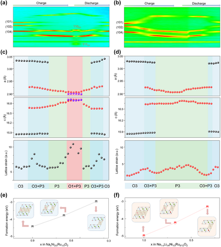
In order to explore the structural evolution in detail, we refined the XRD data and obtained the variation trend of lattice parameters (Figure 4c,d). It can be clearly seen that the lattice parameters of the NNR show a larger variation during the process of O1 phase formation. Nevertheless, only a very small variation can be detected in the NLNR. The retarded multiple-phase transitions of the designed NLNR can be ascribed to the reduced O–O repulsion owing to the negative charge carried by oxygen decreasing with the oxidation of oxygen upon deintercalation of Na ions.[45, 46] Furthermore, the lattice strains (Ɛ) of NNR and NLNR cathodes during the first charge and discharge processes have been calculated based on Williamson–Hall's method. It is worth noting that only a very small microstrain can be detected in NLNR during cycling; meanwhile, there is a large lattice strain for NNR cathode, and the lattice strain particularly becomes larger during the process of O1 phase formation. We further conducted DFT calculations to evaluate the structure stability of both cathodes. As illustrated in Figure 4e,f, the structure stability of NNR and NLNR at different Na de-sodiation states were predicted based on the formation energy, and it was shown that the crystal structures of NLNR are more stable than that of the NNR cathode. Overall, the DFT results well support our experimental results such as in situ XRD.
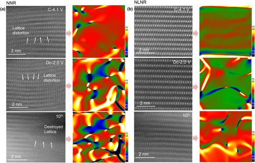
We further quantify the lattice strain evolutions of the two cathode materials at different state of charge and cycles. Figure 5a displays the atomic-resolution images of the NNR; it is shown that there is an evident lattice distortion layer at the 4.1 V-charged state. Moreover, the NNR exhibits broken lattice after experiencing extended cycling process. However, the NLNR shows a slight lattice distortion and inconspicuous structure change accompanied by Na+ extraction and insertion (Figure 5b). Furthermore, the corresponding GPA simulation patterns based on HAADF-STEM were carried out to image the internal stress of both samples. For the NNR, there is an increased inhomogeneous internal strain around the lattice distortion (middle and bottom panel in Figure 5a), which can be reasonably attributed to the increased O–O repulsion and induced multiple phase transitions, thus increasing the lattice strains. Notably, the drastic internal stress may cause the formation and extension of cracks that may adversely affect the stability of layered structure and the diffusion of Na ions.[47-49] In contrast, there is no detectable obvious inhomogeneous interlaminar stress for the cycled NLNR electrode (middle and bottom panel in Figure 5b), showing its structural robustness during prolonged cycling process. This difference can be attributed to the reduced interlayer O–O Coulomb repulsion through pushing charge transfer on oxygen anions, thus displaying retarded phase transitions and inhibited lattice strains. These results in turn account for the comprehensive improvements on electrochemical properties of the NLNR electrode.
3 Conclusions
In summary, we successfully demonstrated our prediction that the lattice strains of layered oxide cathodes during the Na-storage process can be effectively suppressed through pushing the charge transfer on anions. As theoretically supported by DFT calculations and experimentally revealed by ex situ XAS results, the specially designed NLNR sample shows an enhanced charge transfer on anions during the Na extraction process. The triggered charge transfer on anions can not only reduce the Na-O attraction favoring the Na-ion diffusion but also increase the material's redox activity increasing the energy density. As expected, compared with the NNR cathode, the NLNR cathode shows increased rate capability and reversible capacity. More notably, the NLNR cathode shows an excellent long-cycle performance such as a capacity retention of 84% and voltage decay of 0.2 mV/cycle after 300 cycles. Combined with in situ XRD and GPA results, we attributed the superior electrochemical performance of the NLNR cathode to the retarded O3–P3–O1 multiple phase transitions and suppressed lattice strains upon cycling. Our work constructs a coupling relation between the anionic redox and ion-storage lattice strains, and enriches the approaches to achieve a not only stable cycling structure but also high redox activity of layered oxide cathodes.
4 Experimental Section
Materials preparation
The O3-type Na[Ni2/3Ru1/3]O2 and Na[Li1/4Ni1/3Ru5/12]O2 samples were prepared by a typical solid-state sintering method. Stoichiometric precursors of NiO, RuO2, Na2CO3, and Li2CO3 (5% excess to compensate for the volatilization loss at high temperatures) were mixed together and thoroughly ground in agate mortar. The uniformly mixed precursor powders were cold pressed into pellets under a pressure of 5 MPa, and then calcined at 900 °C for 15 h in an O2 atmosphere. After cooling down to room temperature naturally, the samples were immediately transferred to an Ar-filled glovebox for storage.
Materials characterizations
The X-ray diffraction (XRD) characterizations of the as-synthesized powder materials were carried out on an X-ray diffractometer (Persee XD2), using Cu Kα characteristic X-rays, within the 2θ range of 10°–70°. The neutron powder diffraction (NPD) and pair distribution function (PDF) data were collected at the Multiphysics Instrument (MPI) beam of the China Spallation Neutron Source (CSNS). The NPD data were analyzed using GSAS-II software.[28] The PDFgui software package was used to fit the neutron PDF data.[29, 30] A crystal structure model with R3-m space group was adopted for the fitting analysis. X-ray photoelectron spectroscopy (XPS, Thermo Scientific Escalab 250Xi) was used to measure the valence states of Ni and Ru ions. The lattice fringe images and elemental mapping images were obtained by high-resolution transmission electron microscopy (HRTEM, Tecnai G2 F20S-TWIN). The atomic-resolution high-angle annular dark-field scanning transmission electron microscopy (HAADF-STEM) was carried out on a JEM ARM 200F equipment. Ex situ X-ray absorption spectra (XAS) were conducted at 21A X-ray nanodiffraction beamline of Taiwan Photon Source (TPS), National Synchrotron Radiation Research Center (NSRRC). In situ Raman testing was performed on Horiba LabRam HR Evolution. The operando differential electrochemical mass spectrometry (DEMS) spectra were collected using the Jing Pro-TECH PM instrument with QMA250 analyzer and Faraday detector.
Electrochemical measurements
As-prepared active materials were mixed with conductive carbon and polyvinylidene fluoride (PVDF) binder according to the mass ratio of 70:20:10 in N-methyl-pyrrolidone (NMP) to form a uniform slurry, which was uniformly coated on the aluminum foil collector, and then dried in a vacuum oven for 12 h to obtain the working electrode. The loading mass of active material was around 1.6 mg cm−2. All the electrochemical measurements were conducted using CR2032 coin-type cells that assembled in a glove box with argon atmosphere. Sodium metal and glass fiber were used as the negative electrode and separators respectively. The electrolyte is 1.0 M NaClO4 in propylene carbonate (PC), vinyl carbonate (EC), and fluorinated ethylene carbonate (FEC) is used as the electrolyte additive. Galvanostatic intermittent titration technique (GITT) and galvanostatic charge and discharge tests were employed through NEWARE BTS Test control system at room temperature in the voltage range of 2.0–4.1 V (1 C = 130 mA g−1). Potentiostatic intermittent titration technique (PITT) and cyclic voltammetry (CV, 0.1 mV s−1) were tested on the electrochemical workstation of (PGSTAT302N, Autolab).
Theoretical calculations
Density-functional theory (DFT) computations were performed using a Cambridge Sequential Total Energy Package (CASTEP) based on the pseudopotential plane-wave (PPW) method. Electron–ion interactions were described using the ultrasoft (USP) potentials. A plane-wave basis set was employed to expand the wave functions with a cutoff kinetic energy of 420 eV. For the electron–electron exchange and correlation interactions, the functional parametrized by Perdew–Burke–Ernzerhof (PBE), a form of the general gradient approximation (GGA), was used throughout. For the density of states (DOS) calculation, the GGA + U method was applied with the Hubbard U values of 6.8 for Ni and 8.0 for Ru. The vander waals interaction was described using the DFT-D2 method that proposed by Grimme. During the geometry optimizations, all the atom positions were allowed to relax. In this work, the Brillouin-zone integrations were conducted using Monkhorst–Pack (MP) grids of special points with the separation of 0.06 Å−1. The convergence criterion for the electronic self-consistent field (SCF) loop was set to 1 × 10⁻⁶ eV atom−1. The atomic structures were optimized until the residual forces were below 0.03 eV Å−1. The transition state was located via the quadratic synchronous transit (QST) method.
Acknowledgements
This work was supported by the National Natural Science Foundation of China (Grant No. 12105197 and 52088101), Guangdong Basic and Applied Basic Research Foundation (Grant No. 2022A1515010319), the open research fund of Songshan Lake Materials Laboratory (No. 2022SLABFK04), and Large Scientific Facility Open Subject of Songshan Lake, Dongguan, Guangdong. The authors thank Dr. Y. X., Dr. H. C., and Dr. J. X. at Spallation Neutron Source Science Center for the technique help of neutron scattering experiments.
Conflict of interests
The authors declare that they have no known competing financial interests or personal relationships that could have appeared to influence the work reported in this article.


