High-Performance All-Printed Flexible Micro-Supercapacitors with Hierarchical Encapsulation
Abstract
Printed micro-supercapacitors (MSCs) have shown broad prospect in flexible and wearable electronics. Most of previous studies focused on printing the electrochemically active materials paying less attention to other key components like current collectors and electrolytes. This study presents an all-printing strategy to fabricate in-plane flexible and substrate-free MSCs with hierarchical encapsulation. This new type of “all-in-one” MSC is constructed by encapsulating the in-plane interdigital current collectors and electrodes within the polyvinyl-alcohol-based hydrogel electrolyte via sequential printing. The bottom electrolyte layer of this fully printed MSCs helps protect the device from the limitation of conventional substrate, showing excellent flexibility. The MSCs maintain a high capacitance retention of 96.84% even in a completely folded state. An optimal electrochemical performance can be achieved by providing ample and shorter transport paths for ions. The MSCs using commercial activated carbon as the active material are endowed with a high specific areal capacitance of 1892.90 mF cm−2 at a current density of 0.3 mA cm−2, and an outstanding volumetric energy density of 9.20 mWh cm−3 at a volumetric power density of 6.89 mW cm−3. For demonstration, a thermo-hygrometer is stably powered by five MSCs which are connected in series and wrapped onto a glass rod. This low-cost and versatile all-printing strategy is believed to diversify the application fields of MSCs with high capacitance and excellent flexibility.
1 Introduction
With the rapid development of next-generation electronics, the electrochemical energy storage devices (EESDs) move towards being portable, flexible, and wearable.[1-5] Encouragingly, the in-plane interdigital micro-supercapacitors (MSCs) are believed as promising power supplies for next generation flexible electronics, with alluring merits of high specific power, long cycle life and extraordinary stability.[6-8] The traditional sandwich-like MSCs are limited by bulk volume and poor flexibility,[9, 10] while the fiber-like MSCs mostly suffer from complex fabrication processes and non-scalability.[11, 12] The planar MSCs are flexible and free of separators, which are more suitable to be integrated into the microelectronics. Recently, various fabrication technologies like inkjet printing,[13] screen printing,[14] roll-to-roll printing,[15] pen writing,[16] transfer printing[17] and laser printing[18] have been used to produce diverse MSCs. However, these methods still have evident deficiencies such as complicated manufacturing process, waste of materials and mask assistance.[19, 20] In order to fabricate MSCs with high electrochemical performances, it is urgent to conceive a strategy meeting the following requirements: 1) develop an electrode manufacturing process to enable high compatibility with various materials; 2) prepare electrodes and other components without inevitable residuals; and 3) explore a low-cost and high-scalability method to simplify the device fabrication process.
Direct ink writing (DIW) is a popular 3D printing technology that has been applied to make the EESDs.[21] To date, great progress has been achieved in direct-ink-written MSCs. The electrode materials like nanocarbon-based materials,[22] 2D graphene-based materials,[23] conducting polymers,[24] and pseudocapacitive metal oxides[25] have been printed successfully. Thereafter, the printed electrodes with complicated structures can be achieved. Besides, the current collectors and electrolytes have been proven printable, which means it is possible to fabricate the MSCs via a single-time operation. Compared with the combination of multiple technologies, using an all-printing strategy can improve the manufacturing accuracy and efficiency, so as to enhance the electrochemical performances of MSCs.
As yet, a few studies have reported the all-printed MSCs based on the DIW technology. Zhang et al.[26] printed the MSCs with different patterns on different substrates like tapes and clothes. However, it is quite troublesome to control the ink viscosity and printing parameters to fit a new substrate for practical use. Seol et al.[27] demonstrated a sequential all-printing strategy for MSCs including the substrate, current collectors, electrodes and gel electrolyte. Regretfully, the use of acrylonitrile butadiene styrene (ABS) substrate greatly restricts the flexibility of the device. Notably, in most of previous studies, the fully printed MSCs cannot avoid the use of substrates.[28-30] These studies make their devices on the polymer substrates, typically like polyethylene terephthalate (PET). However, the presence of a substrate inevitably increases the thickness of the whole device, which significantly increases the difficulty of integrating the MSCs into microelectronics. The rise of all-in-one EESDs with various shapes provides new ideas for people. This kind of flexible all-in-one device can be easily integrated into the electronics for self-power system.[31-33] However, there are still many challenges to achieve the fabrication of EESDs with all excellent features. Hence, to prepare high-performance MSCs with excellent flexibility, it is essential to consider both printable electrodes and encapsulation methods. In this regard, the hydrogel-based electrolyte brings a new method to address the above issues. The flexibility and safety of MSCs will be improved by encapsulating other components in the hydrogel-based electrolyte films. Moreover, the surrounding electrolytes help shorten the paths for ion transport, resulting in a lower resistance of the device. Besides, optimizing the structure of the electrodes or current collectors is believed to promote a better electrochemical performance of the all-printed MSCs.
Herein, an all-printing strategy is proposed to realize large-scale fabrication of in-plane flexible and substrate-free MSCs. All components of the in-plane solid-state MSCs can be printed via DIW. Polyvinyl alcohol (PVA) gel is used as the solid electrolyte. The two printed electrolyte thin films sandwich the current collector layer and the electrode layer, forming a special hierarchical structure. This hierarchical encapsulation can provide physical protection for the device. Simultaneously, using activated carbon (AC) as the active materials and deionized water as the solvent endows the electrode ink with low cost and environmental friendliness. By adjusting the line width of the silver current collector, the contact area between the electrode and the electrolyte can be coordinated to achieve an optimal electrochemical performance. The all-printed MSCs exhibit a high areal capacitance of up to 1892.90 mF cm−2, an excellent volumetric capacitance of 105.16 F cm−3, and a maximum volumetric energy density of 9.20 mWh cm−3 at a volumetric power density of 6.89 mW cm−3. Without the restriction of the substrate, the all-printed MSCs show better flexibility, and excellent capacitance retention of 96.84% when they are folded. Due to the adhesive properties of the electrolyte, the MSCs can be pasted to any surfaces like a tape. For real application, the all-printed strategy demonstrates outstanding scalability and practicality, which can be extended to other wearable electronics.
2 Results and Discussion
The all-printed MSCs were fabricated in a layer-by-layer pattern as described in Figure 1a. Benefiting from the high compatibility of the entire printing process, different materials could be selected as the substrate. To make the all-printed MSCs easier to be peeled off, a smooth and non-sticky substrate was chosen, example, a PET sheet in this work. The bottom PVA/H3PO4 gel electrolyte layer uses a rectangular pattern. On this layer, the silver ink and activated carbon ink are printed with an interdigitated pattern (Figure S1, Supporting Information). The exposed fingers' edges in limited space provides numerous active sites for adsorption of electrolyte ions, which helps promote the ion penetration into the electrodes and enhance the specific capacitance of the device.[34] Additionally, the interdigitated pattern gets rid of the separator, thus effectively reducing the resistance for ion transfer and improving the charge–discharge performance at high current densities.[35] Finally, another PVA/H3PO4 gel electrolyte layer is printed on the top. The rectangular pattern of the top electrolyte layer covers the interdigitated electrodes exactly. When the whole device is dried, it is easy to peel off the bottom electrolyte thin film from the PET sheet to obtain an in-plane flexible and substrate-free MSC with hierarchical encapsulation. It is noted that, the all-printed MSCs exhibit excellent flexibility and portability without limitation of the substrate.
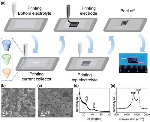
Activated carbons have low cost and stable performances, which can be widely used for commercial supercapacitors. Figure 1b shows the scanning electron microscopy (SEM) image of the activated carbon. The X-ray diffraction (XRD) pattern of the activated carbon (Figure 1d) exhibits two broad diffraction peaks at around 26.4° and 43.6°. The two diffraction patterns are assigned to the carbon basal planes of (002) and (100) respectively, indicating a limited degree of graphitization.[36, 37] Moreover, a large increase in the low angle scatter results from the high density of micropores in the activated carbon.[38] The Raman spectrum (Figure 1e) shows two broad bands at 1341 and 1584 cm−1 corresponding to the diamond (D) and graphite (G) phases of carbon.[39] The relative intensity ratio (IG/ID) of the G band to the D band is 1.18, demonstrating its good structural alignment. The electrode ink represents the typical behavior of the non-Newton fluid (Figure S2, Supporting Information). The shearing-thinning behavior with incremental shear rates ensures the smooth extrusion of the ink through the nozzle. Furthermore, the electrode ink shows a solid-like behavior in the low-stress region. When the stress exceeds the yield point, the electrode ink exhibits a liquid-like behavior. This characteristic enables the consecutive extrusion and rapid curing in the all-printing process. Besides, the SEM image of the printed porous activated carbon electrode is shown in Figure 1c. The porous structure of the printed electrode is conductive to the transport of ions in the electrolyte.
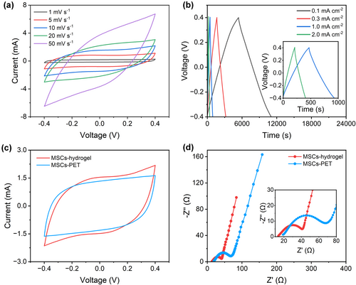
The electrochemical performance of the in-plane flexible and substrate-free MSCs (MSCs-hydrogel) were measured by cyclic voltammetry (CV) at different scan rates from 1 to 50 mV s−1 and galvanostatic charge–discharge (GCD) at various current densities from 0.1 to 2.0 mA cm−2 (Figure 2a,b). The quasi-rectangular shape of CV curves and symmetric triangular shape of GCD profiles exhibit a typical behavior of the electrochemical double-layer capacitor (EDLC). Notably, the capacitance of the silver current collector can be ignored in the all-printed MSCs (Figure S3, Supporting Information). At the current density of 0.1 mA cm−2, the specific areal capacitance is calculated to be 708.59 mF cm−2. To elucidate the advantage of the bottom electrolyte layer, other samples without a bottom electrolyte layer (MSCs-PET) were also prepared (Figure S4, Supporting Information). Obviously, the MSCs with a bottom electrolyte layer exhibit increased area of the CV curves because more contact area of the electrodes and electrolyte is formed (Figure 2c). The specific areal capacitance is enhanced from 390.87 to 416.66 mF cm−2. In addition, the electrochemical impedance spectroscopy (EIS) measurement further corroborates better capacitive behaviors of MSCs-hydrogel than the MSCs-PET (Figure 2d). In the Nyquist plot, the semicircle denotes the charge transfer resistance at the interface between the electrode and electrolyte. The MSCs-hydrogel shows a smaller charge transfer resistance than the MSCs-PET, because of the smaller semicircle. The slope of the low frequency tail indicates the quasi-vertical characteristics, indicating the nearly ideal capacitive behaviors of both MSCs.
In the MSCs-hydrogel, the top and bottom electrolyte layers sandwich the in-plane current collector and electrodes, forming a special hierarchical structure. Unlike the conventional sandwich type, this new architecture has more evident advantages. Firstly, MSCs-hydrogel can get rid of the negative effect of PET sheets. As shown in Figure 3a, bending of the all-printed MSC with the PET sheet inevitably causes small cracks in the electrodes. However, if the MSC is peeled off from the PET sheet, the all-printed MSC can be folded completely without any cracks (Figure 3b). Secondly, the two electrolyte layers play the role of encapsulation. As shown in the schematic of the cross-section of all-printed MSCs (Figure 3c), the current collector and the electrode are protected well by the two electrolyte layers from physical damage. This means that, the electrode with no electrolyte covered cannot resist deformation like bending (Figure S5, Supporting Information). The cross-sectional SEM image of the MSCs-hydrogel clearly proves the successful hierarchical encapsulation and intimate contact between the electrode and the electrolyte (Figure 3d). Furthermore, the elemental mapping reveals the composition of different regions (Figure S6, Supporting Information). Besides, a good contact interface is formed between the electrode and the silver current collector (Figure 3g). Thirdly, the electrolyte layer has an excellent adhesive property due to the presence of hydroxyl groups in H3PO4, enabling it to form H-bonds with PVA. The MSCs-hydrogel can be easily transferred onto any flat or curved surface under special conditions. These MSCs can be pasted onto beakers, tables and even skins, like tapes, demonstrating its excellent compatibility of various application situations (Figure S7, Supporting Information). Moreover, a single MSC-hydrogel can be even rolled with a very small diameter (Figure 3h). As can be seen, no obvious structure damage occurs after recovery (Figure 3i).
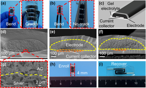
The silver current collector layer is an indispensable part of the all-printed MSC. Despite the use of additional conductive carbon black, the electrical conductivity of the electrode ink is still limited, compared with the silver ink. Previous studies report that, the silver ink has been used for various types of supercapacitors because of its high electrical conductivity.[40-42] In this study, the effect of silver line width is experimentally investigated. According to the width of activated carbon electrode, different silver lines are marked as full width (MSCs-hydrogel), half width (MSCs-hydrogel-2) and quarter width (MSCs-hydrogel-4), respectively. The schematic of the cross-section of MSCs-hydrogel-2 is shown in Figure 3d. The use of a smaller silver line width can provide a larger contact area for the electrode and the bottom electrolyte. Due to the use of a bottom gel electrolyte film, this method can shorten the transport paths of ions among different areas of the electrode. This is quite different from the case when the current collector and the electrode are printed on the PET sheet blocking the free flow of ions. Figure 3e,f show the cross-sectional SEM images of the MSCs-hydrogel-2 and MSCs-hydrogel-4. Due to the use of a small thickness of the silver current collector, the electrode and electrolyte can still maintain good contact. It is clear that, reducing the width of the silver line results in a “micro-stair” between its edge and the bottom electrolyte layer. There is no obvious destruction inside the electrode because of the good fluidity of the electrode ink, making itself “walk downstairs” onto the electrode layer.
The CV curves and GCD profiles of the MSCs-hydrogel-2 are shown in Figure 4a,b. The CV curves of the MSCs-hydrogel-4 are shown in Figure S8, Supporting Information. The CV tests at various scan rates from 5 to 50 mV s−1 and GCD tests at different current densities from 0.3 to 1.5 mA cm−2 also show typical electrochemical capacitive behaviors. The specific areal capacitance is about 1892.90 mF cm−2 at 0.3 mA cm−2, which is higher than most of the printed carbon-based MSCs with different substrates (Table S1, Supporting Information). Figure 4c shows the rate capacity of MSCs-hydrogel-2. When the current density increases from 0.3 to 1.5 mA cm−2, the specific areal capacitance is decreased from 1892.90 to 1017.64 mF cm−2, with a capacity retention of 53.76%. This is ascribed to the large thickness of the electrode, which results in a smaller ion diffusion rate than the electron transfer rate at high current densities. The biggest integration area of CV curves well proves the distinguished capacitive performance of MSCs-hydrogel-2 (Figure 4d). According to the Nyquist plots (Figure 4e), the RES value of MSCs increases with the decrease of the silver line width. Benefiting from the increased contact area of the electrode and the bottom gel electrolyte (by decreasing the silver line width), there is a dramatical decrease of the semicircle diameter in the high-frequency region. As for the tail at a low frequency, the slopes of MSCs-hydrogel-2 and MSCs-hydrogel-4 are nearly the same, which is larger than the MSCs-hydrogel. This is because the ample and shorter ions transport paths for between the electrode and electrolyte, leading to lower charge transfer resistance and diffusion resistance. The Ragone plot shown in Figure 4f demonstrates the maximum volumetric energy density of 9.20 mWh cm−3 at a volumetric power density of 6.89 mW cm−3 and the maximum volumetric power density of 33.12 mW cm−3 at a volumetric energy density of 4.57 mWh cm−3, which precedes the previously reported carbon-based supercapacitors fabricated by 3D printing technology. The value of the maximum volumetric energy density is approximately twice of the screen printing mesoporous activated carbon MSCs,[43] five times of the direct ink writing Fe2O3/graphene MSCs[44] and the inkjet printing graphene MSCs,[45] 10 times of the screen printing MXene MSCs,[46] 20 times of the direct ink writing graphene-carbon sphere (G-CS) MSCs[47] and the direct ink writing nitrogen/oxygen-doped graphene (NOG) MSCs.[48] Furthermore, the results of MSCs-hydrogel-2 are also much higher than the Li thin-film battery.[49]
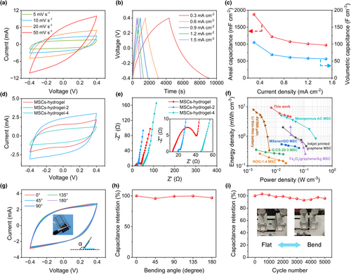
The flexibility of MSCs is crucial for wearable electronics applications. To evaluate this characteristic, a group of bending tests at different bending angles were conducted, as shown in Figure 4g. The CV curves of MSCs-hydrogel-2 (at a scan rate of 10 mV s−1) acquired at different bending angles show negligible changes in the shape and enclosed area. The all-printed MSCs show extremely high stability since the capacitance maintains above 95% all the way at different bending angles (Figure 4h). For comparison, the MSCs-PET were tested in the same way. The dramatic decrease of the capacitance in the extreme bending state reveals the poor flexibility of MSCs-PET, which is not as good as MSCs-hydrogel-2 (Figure S9, Supporting Information). The bending stability of MSCs-hydrogel-2 was measured at a scan rate of 50 mV s−1 every 500 cycles (totally 5000 cycles; Figure 4i). Although the fluctuation of capacitance retention can be observed, the value of the retention retains over 90% during the whole process, indicating excellent flexibility and operation stability of the as-prepared devices.
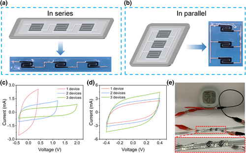
For practical applications, a single MSC cannot provide enough power for devices, so multiple MSCs need to be connected in series or parallel to meet the real demand for voltage and current output. To demonstrate the universality of this all-printing strategy, two energy systems assembled in series or in parallel were prepared (Figure 5a,b). The all-printing process is almost the same as the fabrication of a single in-plane flexible and substrate-free MSC. The differences lie in the pattern of the silver current collector, extending the silver line to connect each other. Besides, the PVA based hydrogel is printed as the bottom rectangle film to support other printed components. The size of the rectangle will change with the number of the devices. Figure 5c shows the CV curves of three serially connected all-printed MSCs tested at 10 mV s−1. It can be seen that, the voltage window is increased linearly from 0.8 to 2.4 V. The CV curves of three all-printed MSCs assembled in parallel are displayed in Figure 5d. The area of CV curves is coupled with the number of MSCs connected in parallel. The future energy storage devices are supposed to have more advantageous features such as shape diversity, fast and large-scale manufacturing, and small size to be easily integrated with other units to meet the high output. Therefore, to further evaluate the applicability of our all-printed MSCs, five serially connected MSCs were prepared for high-voltage applications. This integrated device is wrapped around the surface of a glass rod with a diameter of 5 mm, pasted to the surface of the glass rod like a tape. This test benefits from the adhesive properties of the bottom electrolyte layer. As shown in Figure 5e, the fully charged all-printed MSCs can successfully drive a digital thermo-hygrometer.
3 Conclusions
In summary, this work demonstrates a facile fabrication of the in-plane flexible and substrate-free MSCs with hierarchical encapsulation. These MSCs have been fabricated via encapsulating the activated carbon electrodes and silver current collectors inside the H3PO4/PVA gel electrolyte by a sequential all-printing strategy. The new-concept MSCs promote higher electrochemical and mechanical performances than most of other printed carbon-based in-plane MSCs reported previously. The bottom electrolyte layer and the width of the silver current collector have a significant influence in the electrochemical performance of the all-printed MSCs. The specific areal capacitance can be improved to 1892.90 mF cm−2 by adjusting the width. Simultaneously, the all-printed MSCs yield an outstanding volumetric energy density of 9.20 mWh cm−3 at a volumetric power density of 6.89 mW cm−3. In addition, the MSCs connected in series also display outstanding behaviors in practical usage. As a demonstration, the DIW technology and all-printing strategy are low cost, environmentally friendly, scalable and highly customizable, which will be shined in multiple fields, such as biomedicine, flexible and wearable devices, intelligent detection and so on.
4 Experimental Section
Materials
The commercial activated carbon was purchased from Nanjing MKNANO Tech Co., Ltd. Carbon black (CB) and styrene butadiene rubber (SBR) binder were supplied by Shenzhen Kejing Star Technology Co., Ltd. carboxymethyl cellulose (CMC), PVA-224 (~20 500 MW) and phosphoric acid (85 wt.%) were acquired from Aladdin Industrial Inc. Silver ink was purchased from Guangzhou Kaixiang Co., Ltd.
Preparation of activated carbon electrode ink
To prepare the activated carbon electrode ink, activated carbon (88 wt.%), CB (10 wt.%) CMC (1 wt.%) and SBR (1 wt.%) were added into deionized water and mixed in a planetary centrifugal mixer (Shenzhen Hasai), forming a stable and viscous ink. The proportion of the CMC/SBR binder in the electrode ink was only 2%, which was much less than the conventional level (10%). The low content of binder was used to minimize its influence on the electrochemical performance of the electrode without affecting the structural integrity of the electrode.
Preparation of PVA/H3PO4 gel electrolyte ink
For preparation of the PVA/H3PO4 gel electrolyte ink, PVA powder (3 g) was firstly dispersed in deionized water (30 mL) at 85 °C water bath under magnetic stirring. Until the gel dispersion was completely clean, H3PO4 (85 wt.%) was slowly added into PVA solution with weight ratio of 1:1 regarding PVA powder. After magnetic stirring for 1 h at the room temperature, the H3PO4/PVA gel electrolyte ink was prepared.
Patterns design
Printing patterns of the current collector and the electrode were designed as paper clips. To ensure the integrity and continuity of a single electrode, interdigitated patterns of the current collector and electrode layer were finished by one-stroke drawing for each electrode. The line of the current collector was longer than the electrode layer, for the convenience of electrochemical testing.
All-printing process
The silver ink, activated carbon electrode ink and PVA/H3PO4 gel electrolyte ink were printed by a DIW dispenser (F4200N.1). For the printing process, the gel electrolyte ink was firstly printed onto the PET sheet to form a thin film. After 12 h of drying in natural air, the silver ink and the electrode ink were sequentially printed onto the gel electrolyte. The width of the silver line was controlled by the diameter of the printing nozzles. Then, the gel electrolyte ink was printed again to cover the electrode area. After sufficient drying, it was easy to peel off the bottom electrolyte thin film from the PET sheet. Finally, in plane flexible and substrate-free MSCs with hierarchical encapsulation was obtained. The size of the printing platform was 150 mm × 200 mm. The area of a single all-printed MSC was 10 mm × 28 mm. This DIW dispenser can easily realize large-scale manufacturing of the all-printed MSCs in a short time.
Characterization
An electrochemical workstation (PGSTAT302N; AUTOLAB) was used for electrochemical measurements. CV curves were tested in the scan rates ranging from 1 to 100 mV s−1. GCD profiles were obtained at various current densities from 0.1 to 1.5 mA cm−2. The EIS was measured under the frequency range from 0.01 Hz to 100 kHz. The structure of the activated carbon was characterized by XRD (X'pert Powder) and Raman spectroscopy (LabRAM Aramis). Cross-section morphology and structure of all-printed MSCs were characterized by SEM (Zeiss Merlin). The rheological properties of the activated carbon electrode ink were measured in the rheometer (Thermo Scientific HAAKE MARS 40).
Acknowledgements
This work was financially supported by National Natural Science Foundation of China (Nos. U22A20193 and 51975218), and Fundamental Research Funds for the Central Universities (No. 2022ZYGXZR101).
Conflict of Interest
The authors declare no conflict of interest.


