Porous Indium Nanocrystals on Conductive Carbon Nanotube Networks for High-Performance CO2-to-Formate Electrocatalytic Conversion
Abstract
Ever-increasing emissions of anthropogenic carbon dioxide (CO2) cause global environmental and climate challenges. Inspired by biological photosynthesis, developing effective strategies NeuNlto up-cycle CO2 into high-value organics is crucial. Electrochemical CO2 reduction reaction (CO2RR) is highly promising to convert CO2 into economically viable carbon-based chemicals or fuels under mild process conditions. Herein, mesoporous indium supported on multi-walled carbon nanotubes (mp-In@MWCNTs) is synthesized via a facile wet chemical method. The mp-In@MWCNTs electrocatalysts exhibit high CO2RR performance in reducing CO2 into formate. An outstanding activity (current density −78.5 mA cm−2), high conversion efficiency (Faradaic efficiency of formate over 90%), and persistent stability (~30 h) for selective CO2-to-formate conversion are observed. The outstanding CO2RR process performance is attributed to the unique structures with mesoporous surfaces and a conductive network, which promote the adsorption and desorption of reactants and intermediates while improving electron transfer. These findings provide guiding principles for synthesizing conductive metal-based electrocatalysts for high-performance CO2 conversion.
1 Introduction
The rapid increase in industrial production and human activities leads to excessive carbon dioxide (CO2) emissions, which causes climate change and environmental extremes.[1-3] Reducing excess CO2 in the atmosphere, particularly using sustainable or low-carbon processes, is still a major challenge in modern society. Some CO2 is absorbed through plant photosynthesis for balancing natural carbon, but the conversion efficiency is relatively low (normally <2%).[4] Inspired by biological photosynthesis, the design of bioinspired artificial photosynthesis systems converting CO2 to value-added carbon-based chemicals has attracted wide attention.[5, 6] Although formate (HCOO−) is the product of a two-electron transfer of CO2 reduction reaction, conversion into formate or formic acid is poised to deliver the highest economic benefit.[7] Electrocatalytic CO2 reduction reaction (CO2RR) is a promising approach due to mild conditions and simple operations.[8-10] However, CO2RR is a multi-electron transfer reaction accompanied by many side reactions, especially the hydrogen evolution reaction (HER), which is challenging to avoid.[11] Therefore, it is crucial to improve the product selectivity. Moreover, the high thermodynamic stability of CO2 requires a large amount of energy to break the strong carbon–oxygen double bond (C=O).[12] Therefore, appropriate electrocatalysts should be selected and customized to enable high-performance (high conversion efficiency, selectivity, and durability) of CO2RR to formate or formic acid, ultimately, leading to socio-economic and environmental benefits.
Main group metal-based nanocatalysts, such as bismuth (Bi),[13-15] tin (Sn),[16-18] and indium (In),[19, 20] emerge as outstanding candidates for CO2RR to produce formate from CO2. Among them, In is of special interest due to its nontoxicity, environmental friendliness, and excellent selectivity. Although In is one of the relatively rare elements, it performs well in CO2RR, as it has a strong ability to break C=C bonds with the outstanding catalytic selectivity (formic acid as the main reduction product) and has the ability to inhibit the HER side reaction. In previous studies, In demonstrated suitable properties for CO2RR and the ability to inhibit the HER side reaction; however, In-based catalysts typically suffer from the inferior current density, limiting further applications.[7, 9] Hori et al.[21] reported that In had reasonable selectivity for converting CO2 to formate but only exhibited a current density of 5 mA cm−2. A relatively low current density (5.8 mA cm−2) was also observed, along with dendrite formation in In electrodes.[22] A common obstacle for In nanoparticles and their aggregates is their limited structural and morphological flexibility, leading to small specific surface areas and insufficient reactive sites. Recent studies reveal that developed porous structures with enlarged surface areas and denser active sites effectively promote the reaction process and improve electrocatalytic performance.[23, 24] Three-dimensional (3D) hierarchical porous In electrocatalysts obtained from electrochemical deposition exhibited remarkably high current densities of 60 mA cm−2 and a high conversion efficiency to formate of ~90%.[25] Nevertheless, developing custom-designed porous In-based nanostructures via common wet chemical methods remains challenging due to the unique physicochemical properties of In.
Additionally, the conductivity of electrocatalysts also affects the performance of CO2RR.[26-28] During CO2 electroreduction, electrons are generally transferred from the catalyst or electrode interface to generate the reaction products. The electrocatalysts with better conductivity can facilitate electron transfer and promote the CO2RR.[29-33] However, the conductivity of metal-based heterogeneous catalysts is generally poor due to insufficient Schottky contact between the catalysts and supports arising from imperfections in metal coating techniques (e.g., printing metal inks) on the electrodes.[23, 34-36] Therefore, higher conductivity of the electrocatalysts helps improve the electrocatalytic performance. One possible solution is based on multi-walled carbon nanotubes (MWCNTs) which have attracted widespread attention because of their high electronic conductivity, remarkable interfacial contact, and developed capabilities for large-scale production. When applied as catalyst supports, MWCNTs can provide conductive networks and prevent metal nanoparticle aggregation.[32, 37, 38] Our innovative solution is thus based on the hypothesis that a combination of In metal and MWCNTs can significantly enhance the electrode conductivity and, consequently, the electrocatalytic performance of the In-based catalysts.
Herein, mesoporous In nanocrystals anchored on functionalized MWCNTs (defined as mp-In@MWCNTs) were successfully synthesized via a facile wet chemistry method under mild conditions, allowing for reducing the amount of In used while maintaining excellent catalytic activity. Sodium borohydride (NaBH4) and MWCNTs were selected as the reducing agent and catalyst supports, respectively. The as-prepared mp-In@MWCNTs possess unique morphological architectures with the unique porous structure not common to commercial In catalysts, complemented with high surface areas and a developed conductive network, providing an electron transfer pathway and improving the catalytic activity. Consequently, mp-In@MWCNTs electrocatalysts show excellent performance for CO2-to-formate conversion, with a high current density of −78.5 mA cm−2 obtained. Meanwhile, the outstanding Faradaic efficiency to formate () of more than 90% over a wide potential range from −0.8 to −1.0 V and superior stability over 30 h were achieved. This work offers new insights into metal-based electrocatalysts with high conductivity for high-performance CO2-to-formate conversion.
2 Results and Discussion
2.1 Structural and Characterization of mp-In@MWCNTs Hydride Nanocatalysts
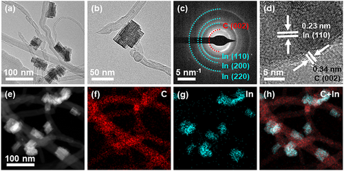
The mp-In@MWCNTs were synthesized in a single-step process based on the previously reported methods.[39] Indium salt precursor (InCl3) was dissolved in an aqueous solution containing uniformly dispersed MWCNTs. After the mixed solution was heated to 60 °C for 10 min, NaBH4 aqueous solution was added as a reducing agent. As shown in Figure 1a and Figure S1, Supporting Information, the mesoporous In nanocrystals anchored on MWCNTs were obtained. The mp-In consisted of porous nanoplates and possessed hierarchical porous structures (Figure 1b), which offered more unsaturated bonds and active sites. The average length of indium nanocrystals was 54.8 ± 15 nm, with an average width of 29.6 ± 10 nm (Figure S2, Supporting Information). As confirmed by the selected area electron diffraction (SAED) in Figure 1c, the diffraction rings of 0.23, 0.16, and 0.11 nm correspond to (110), (200), and (220) crystal planes along the [001] band axis, respectively, suggesting that mp-In was composed of metal In with a polycrystalline structure. The inner diffraction rings at 0.34 nm are attributed to the crystal plane (002) of MWCNTs. Additionally, as revealed by the high-resolution TEM (HRTEM) in Figure 1d, the lattice fringes with distances of 0.23 nm are assigned to the crystallographic plane (110) of tetragonal indium metal. The space of 0.34 nm corresponds to the plane (002) of MWCNTs, indicating the successful synthesis of mp-In@MWCNTs composite nanomaterials. The energy-dispersive X-ray spectroscopy (EDS) analysis in Figure S3, Supporting Information is consistent with the results for the composite material made of carbon nanotubes and indium nanocrystals. As can be seen from the high-angle annular dark field scanning TEM (HAADF-STEM) and elemental mapping (Figure 1e–h) analyses, the homogeneous dispersion of In elements (cyan) decorated on the nanocrystals and C elements (red) is distributed uniformly on the MWCNTs support.
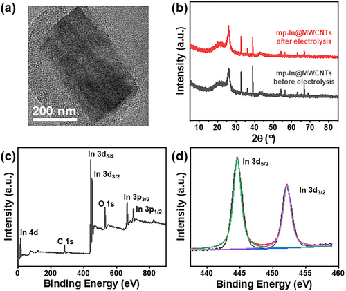
The obtained mp-In@MWCNTs nanocatalysts were further characterized using powder X-ray diffraction (XRD). In the XRD spectrum, the main diffraction peaks at 32.9, 36.3, and 39.2 (blue curve in Figure 2a) were assigned to the (101), (002), and (110) crystal planes in tetragonal indium [PDF # 85-1409], respectively. The peaks of indium oxide and hydroxide were not found in the XRD spectrum, revealing that the porous nanomaterials mainly contain indium metal, rather than indium oxide or hydroxide. The diffraction peak confirmed the existence of MWCNTs in the complex at 26.2°, which corresponds to the (002) plane of carbon. The sharp diffraction peaks indicated a high crystallinity, consistent with the HRTEM image in Figure 1d. The surface chemical composition of mp-In@MWCNTs was investigated by X-ray photoelectron spectroscopy (XPS). The nanocatalysts were composed of indium without impurity elements as inferred from a full-scan XPS spectrum from 0 to 900 eV binding energies in Figure 2c, which is consistent with the results of EDS analysis in Figure S3, Supporting Information. Furthermore, Figure 2d presents the In 3d XPS spectrum with In valence states. The deconvolution of In 3d XPS spectrum revealed two peaks at 443.7 and 451.4 eV, corresponding to In 3d5/2 and In 3d3/2 states, respectively, suggesting the existence of the In (0) state,[20, 39, 40] rather than the other common valence state indium (III), further suggesting the absence of indium oxide or hydroxide in the nanocatalysts. This finding confirms that the as-prepared mp-In@MWCNTs nanocatalysts are more stable in the ambient atmosphere compared to commercial indium catalysts (Figure S4, Supporting Information).

Nitrogen gas adsorption–desorption isotherms were measured to investigate the specific surface areas and pore distribution of the as-prepared mp-In@MWCNTs nanocatalysts. As shown in Figure 2b, mp-In@MWCNTs showed a clear hysteresis loop, indicating the presence of well-defined mesoporous structures in the composite catalysts. The specific surface areas of mp-In@MWCNTs and commercial In were found to be 543 and 66 m2 g−1, respectively, based on the Brunauer–Emmett–Teller (BET) results. The maxima of the pore size distribution in mp-In@MWCNTs were approximately at 1.5 and 2 nm, as revealed using the Barrett–Joyner–Halenda (BJH) method. The porous structure of mp-In anchored on MWCNTs can be attributed to the hydrogen gas evolution from the catalytic hydrolysis of sodium borohydride serving as geometric templates.[39] However, commercial In catalysts had almost no porous structures (Figure S5, Supporting Information). The surface dangling bonds and unsaturated sites on mp-In@MWCNTs would promote the catalytic performance.
2.2 CO2 Reduction Reaction Performance of mp-In@MWCNTs Nanocatalysts
The CO2 electroreduction performance using mp-In@MWCNTs composite nanocatalysts was evaluated in a Nafion-117 membrane-separated H-type cell. Linear sweep voltammetry (LSV) curves of mp-In@MWCNTs and commercial In electrocatalysts were measured in a CO2-saturated 0.1 m KHCO3 solution at room temperature (Figure 3a). The mp-In@MWCNTs exhibited a higher current density of −78.5 mA cm−2 at −1.2 V, while commercial In showed a current density of −16.0 mA cm−2 at −1.2 V under the same conditions. Meanwhile, a more positive onset potential at about −0.7 V for mp-In@MWCNTs was observed in LSV curves compared with the commercial In, indicating significantly higher electrocatalytic activities of CO2RR for the mp-In@MWCNTs catalyst. The CO2 electroreduction was also tested in a flow cell shown in Figure S6, Supporting Information, the LSV curve acquired in a flow cell was similar to the LSV curve acquired in a H-type cell, indicating negligible influence in cells and convincing results. The LSV curves were also obtained for an Ar-saturated 0.1 m KHCO3 solution to evaluate the hydrogen evolution side reaction. Both mp-In@MWCNTs and commercial In nanocatalysts displayed lower current densities in Figure 3a, due to the intrinsic low activity toward HER of metal In.[7] Nevertheless, mp-In@MWCNTs still showed a higher activity result from the porous structure of indium nanocatalysts and carbon nanotube framework.
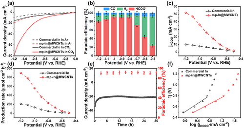
To quantify the reaction products and assess the selectivity toward CO2RR, the controlled electrolysis measurements were performed for 1 h under the potentials varied from −0.5 to −1.2 V in a CO2-saturated 0.1 m KHCO3 solution. Using nuclear magnetic resonance (NMR) analysis and gas chromatography (GC), the products generated from CO2RR were detected and quantified. Formate was the predominant CO2RR product for mp-In@MWCNTs, accompanied by a small amount of CO and H2. Other carbonaceous chemicals were not detected, neither liquid nor gaseous products. As shown in Figure 3b, the Faradaic efficiencies of different products (HCOO−, H2 and CO) were calculated at different potentials on mp-In@MWCNTs. At −0.5 V negative potential, the Faradaic efficiency of formate () was firstly measured to be 23.7%, while the FE of H2 (FEH2) was up to 69.2% due to the competing HER side reaction. When the potential was raised to −0.8 V, rapidly increased to 91.0%. maintained >90% in a broad potential range from −0.8 to −1.0 V accompanied by the suppressed HER with FEH2 of 6%. When the applied potential was shifted to more negative values of −1.1 and −1.2 V, gradually declined due to the diffusion-limited process of reactant CO2 molecules and the associated mass transfer.[41-43] During the electrolysis of CO2, the FE of CO remained at a relatively low level of 6%. Additionally, to further distinguish the properties of mp-In@MWCNTs toward CO2RR, the commercial In was also tested as a CO2RR electrocatalyst. As shown in Figure S7, Supporting Information, the commercial In exhibited ~70% (which is much lower than for the mp-In@MWCNTs) at potentials between −0.8 and −1.0 V and peaked at 71.2% at −0.9 V, indicating a much higher overpotential. These findings confirmed that mp-In@MWCNTs possessed a high activity and selectivity for converting CO2 to formate in a wide potential range, which is consistent with the main group of metal-based electrocatalysts (e.g., Sn, Bi and Pb) for CO2 conversion to formate.[7]
In addition, the formate partial current density of mp-In@MWCNTs and commercial In was calculated and plotted against the applied potential, as shown in Figure 3c. A superior current density of = 51.9 mA cm−1 was observed at −1.2 V on mp-In@MWCNTs, which is five times higher than 9.9 mA cm−1 for the commercial In catalyst. Meanwhile, Figure 3d shows the formate production rate during CO2RR. The mp-In@MWCNTs showed a higher production rate of 898.6 μmol cm−2 h−1 than 208.6 μmol cm−2 h−1 for the commercial In catalyst. The superior catalytic activity and excellent selectivity in a wide operating potential window for mp-In@MWCNTs demonstrated the competitive electrocatalytic performance of CO2RR toward formate conversion compared with other In-based CO2RR catalysts (Table S1, Supporting Information).
The electrochemical stability is also an important indicator of catalytic performance. To further evaluate the performance stability of the new mp-In@MWCNTs catalysts, the long-term CO2RR tests were performed in 0.1 m KHCO3 electrolyte with CO2-saturation. A flow rate of CO2 (20 mL min−1) was let into the cathodic compartment. As shown in Figure 3e, during 30 h long-term CO2RR electrolysis at −1.0 V, the current density demonstrated a negligible decay at approximately −20 mA cm−2, and the FE of formate remained unchanged at over 90%. Meanwhile, the morphology and crystalline structure of mp-In@MWCNTs were characterized after the long-term tests, and maintained almost unchanged, as shown in Figure 4a,b. The valence state of metallic In(0) was determined from the XPS analysis of mp-In@MWCNTs in Figure 4c,d. The results indicated that the mp-In@MWCNTs catalyst possessed excellent electrochemical durability.
To understand the reaction kinetics of CO2 reduction on the surface of mp-In@MWCNTs, the Tafel slope was calculated and is presented in Figure 3f. In the low-current-density regions, the CO2 reduction reaction was mainly limited by electro-kinetics.[40, 42, 44] The mp-In@MWCNTs featured a Tafel slope of 134 mV dec−1, which was close to 118 mV dec−1, suggesting that CO2RR on mp-In@MWCNTs was limited by the initial one-electron transfer to convert an adsorbed intermediate. While the Tafel slope for commercial In was much higher at 150 mA cm−2, which is inferior compared to the mp-In@MWCNTs. It is well known that the rate-determining step of CO2RR is the initial electron transfer from the electrode to the for conversion of . The faster initial electron transfer for CO2 molecules to form the adsorbed intermediate on the surface of mp-In@MWCNTs ensured the improved CO2RR performance.
2.3 Origin of the Improved Activity and Selectivity of mp-In@MWCNTs Nanocatalysts
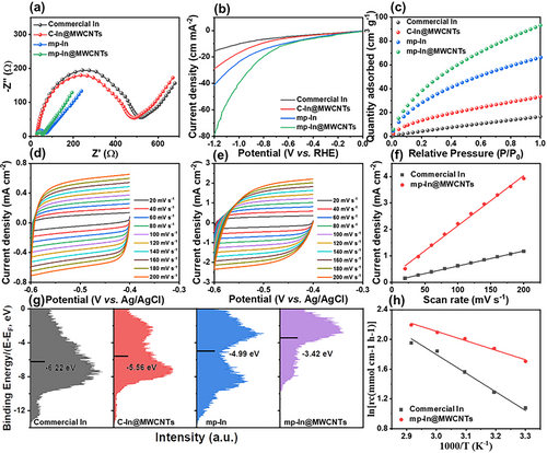
The above results suggest that the outstanding CO2RR performance is primarily related to the unique structural features of the mp-In@MWCNTs catalytic structures. Mesoporous In nanocatalysts possessed enriched unsaturated sites and abundant dangling bonds on the surfaces, promoting the adsorption and desorption of CO2 molecules and intermediates and facilitating CO2 reduction. This work used carboxylic acid-modified MWCNTs as a support network in mp-In@MWCNTs, thus ensuring good electrical conductivity. As presented in Figure 5a, electrochemical impedance spectra (EIS) analyses were carried out in 0.1 m KHCO3 to measure the ohmic resistance over the catalysts. The Nyquist impedance plots showed smaller impedance arcs for the mp-In@MWCNTs than for the mp-In nanocatalysts, indicating the higher electron transfer rate from indium nanocrystals to CO2. We emphasize that highly conductive MWCNTs promoted the electronic conductivity, catalytic performance, and electron-transfer kinetics on the prepared mp-In@MWCNTs electrodes. In addition, the composite In catalyst has a higher conductivity than commercial In. To confirm the increased current density on mp-In@MWCNTs, the LSV curves on mp-In without MWCNTs supports were obtained for CO2-saturated 0.1 m KHCO3 as control experiments. The current density of −41.8 mA cm−2 at −1.2 V for mp-In was inferior to −78.5 mA cm−2 on mp-In@MWCNTs in Figure 5b, confirming the reduced charge transfer resistance. These results suggest that a higher electronic conductivity leads to a higher current density and an improved electrochemical reduction on the mp-In@MWCNTs catalysts, allowing for reducing the amount of In used (containing 15.0% indium measured by ICP) while maintaining excellent catalytic activity.
Additionally, the structure of mp-In@MWCNTs was formed by In nanocrystals activating CO2RR and a three-dimensional framework of carbon nanotubes. Figure S8, Supporting Information displays the Zeta potentials of In nanocrystals, MWCNTs modified by carboxylic acid, and mp-In@MWCNTs. The corresponding Zeta potential for MWCNTs, In nanocrystals and the composite mp-In@MWCNTs was −17.6, +1.6, and −9.2 mV, respectively. The observed Zeta potential in mp-In@MWCNTs suggested the strong electrostatic attraction between the In nanocrystals and MWCNTs ensuring the excellent durability of mp-In@MWCNTs.
Based on the previous studies,[34, 39, 45] the mesoporous structure of mp-In@MWCNTs was another determining factor in enhancing the CO2RR performance by improving the adsorption and desorption of intermediates and facilitating the CO2RR. The mp-In@MWCNTs contained more edges, low coordinated surface sites and MWCNTs supported framework, thereby enhancing the adsorption of CO2 molecules. The volumetric adsorption of CO2 was performed at 273 K, and the adsorption capacity is shown in Figure 5c. The amount of CO2 adsorption capacity reached 93.25 cm3 g−1 on mp-In@MWCNTs, which is much higher than 66.28 cm3 g−1 (mp-In), 33.27 cm3 g−1 (commercial In@MWCNTs), and 16.46 cm3 g−1 (commercial In). The significantly enhanced adsorption capacity is conducive to the lower potential and high FE of formate in the CO2RR. Meanwhile, the abundant active sites of mp-In@MWCNTs contributed to the larger electrochemical surface area (ECSA).
To further assess the ECSA of electrocatalysts, the cyclic voltammograms (CV) were performed at different scanning rates based on the double-layer capacitance (Cdl) method.[39] Figure 5d,e show the CV curves corresponding to mp-In@MWCNTs and commercial In catalysts. As shown in Figure 5f, Cdl of mp-In@MWCNTs was estimated to be 19.0 mF cm−2, which is 3.5 times larger than 5.6 mF cm−2 for the commercial In, indicating more electrochemically active sites available on the surface of the mp-In@MWCNT catalysts.
Furthermore, the unsaturated coordination sites and edge dangling bonds on the surface of mp-In@MWCNTs could stabilize reaction intermediates and decrease the activation energy Ea.[39, 46-48] Compared with the uncatalyzed reactions, a reaction path with the lower activation energy is enabled by the mp-In@MWCNTs catalyst, thus raising the reaction rate. The value of Ea was estimated by the Arrhenius equation via the electrolysis reactions at different temperatures. As shown in Figure 5h, the mp-In@MWCNTs catalyst exhibited a lower value of Ea of 12.7 kJ mol−1, while the calculated value of Ea was 25.1 kJ mol−1 for the commercial In catalyst. These results suggest the lower activation barrier for the key step and CO2 activation on the mp-In@MWCNTs catalyst due to the increased exposed active sites in the unique porous structure. In addition, the d-band center (relative to the Fermi level) of the electrocatalysts indicated the binding strength of the intermediate. As shown in Figure 5g, the d-band center of mp-In@MWCNTs after the integration with MWCNTs was −3.42 eV (up-shifted close to the Fermi level), indicating that the introduction of MWCNTs promoted the electron-donation effect from indium to CO2 and intermediates. Compared with mp-In nanocatalysts with the d-band center of −4.99 eV, the upshift of the d-band for mp-In@MWCNTs structures suggested that the stronger binding of intermediate OCOH* promoted CO2 reduction due to the shift of the anti-bonding states above the Fermi level.
3 Conclusion
Electrocatalytic CO2 reduction is a promising approach to help address global carbon emissions challenges. However, the issues of catalyst efficiency and durability still pose significant challenges for energy chemistry research. The mp-In@MWCNTs catalyst of this work featuring the unique porosity (not common to commercial In catalysts), developed conductive networks, high conversion performance, and stability provides an innovation solution to these challenges. The mp-In@MWCNTs electrocatalysts were prepared using a facile wet chemical method with NaBH4 and MWCNTs as the reductant and support, respectively. Hydrogen evolution from the hydrolysis of NaBH4 introduced the unique porous structure, promoting the adsorption and desorption of CO2 molecules and intermediates. Consequently, the superior performance of CO2RR was achieved on the mp-In@MWCNTs catalysts. The current density was 78.5 mA cm−2, and the remained at over 90% on a broad potential range from −0.8 to −1.0 V. Moreover, a long-term test for 30 h was carried out, confirming the durability of the mp-In@MWCNTs catalyst for CO2RR (90% FE, a stable current density of 20 mA cm−2 at −1.0 V). The MWCNTs catalyst support provides conductive networks to facilitate electron transfer, enhancing the performance of the In-based catalysts for CO2RR. Finally, the developed new mp-In@MWCNTs catalyst with the unique porous structure and conductive network is a promising candidate for next-generation clean energy technologies.
4 Experimental Section
Chemicals
Electrocatalyst synthesis
Before synthesis, 100 mg MWCNTs were dispersed in 20 mL H2O. Then, 132.7 mg InCl3 was added to the mixed solution. After that, the mixed aqueous solution was heated to 60 °C. Meanwhile, 22.7 mg NaBH4 was dissolved in 20 mL H2O. The NaBH4 aqueous solution was dropped into MWCNTs and InCl3 mixed solution. The synthesis reaction proceeded vigorously and stirred for around 10 min at atmospheric pressure. Finally, the black precipitates were collected by centrifugation and were washed with deionized water. After oven-drying, the prepared sample was stored and termed mesoporous indium @ multi-walled carbon nanotubes (labeled as mp-In@MWCNTs). 132.7 mg InCl3 was also dissolved in 20 mL H2O without MWCNTs. The InCl3 aqueous solution was heated to 60 °C before NaBH4 (22.7 mg in 20 mL H2O) aqueous solution was added. After the mixed solution refluxes for 10 min, the silver-gray sediments were collected. And they were washed with deionized water, dried in an oven, and termed mp-In. Commercial indium nanoparticles were mixed with MWCNTs, thus producing the structure made of indium nanocrystals supported on MWCNTs (defined as C-In@ MWCNTs).
Electrochemical measurements
The electrochemical surface area (ECSA) of the electrocatalysts was expressed in terms of electrochemical double-layer capacitance (Cdl). In a non-Faradaic region between −0.4 V and −0.6 V, the CV curves were recorded to measure the Cdl at different scan rates (Vb) in Ar-saturated KHCO3 aqueous solution. The Cdl values were calculated via the slopes of the plots of capacitive currents as a function of the scan rates. The ECSA was proportional to Cdl.[49] Electrochemical impedance spectra (EIS) were acquired in 0.1 mol L−1 KHCO3 aqueous solution. The AC voltage amplitude was 5 mV, and the voltage frequencies ranged from 0.1 to 105 Hz.
Product analysis
Microscopy and microanalysis
Transmission electron microscope (TEM) images, high-resolution TEM (HRTEM) images and high-angle annular dark field-scanning transmission electron microscopy (HAADF-STEM) images were acquired using ThermoFisher Scientific Talos and FEI F20 microscopes operated at 200 kV. The energy-dispersive X-ray spectrum (EDS) and the corresponding elemental mapping were obtained from an FEI Tecnai Talos with an acceleration voltage of 200 kV. A Bruker-axs with Cu Ka X-ray source was used to detect X-ray diffraction (XRD) patterns operated at 40 kV and 40 mA. The chemical composition of mp-In@MWCNTs was characterized via X-ray photoelectron spectroscopy (XPS). The Escalab 250Xi from ThermoFisher Scientific with an X-ray source of Al Ka was applied to collect detailed information on the chemical composition. Software XPS peak41 was employed to deconvolute the curves and fit the results. The surface valence band spectra of the catalysts were obtained via high-resolution XPS with an energy range of 0–20 eV and each spectrum was collected over ~1000 scans. The surface areas and pore distribution were measured using N2 adsorption–desorption analysis via a Micromeritics TriStar II Plus, which was also used to quantify the amount of adsorbed CO2.
Acknowledgements
L.X. thanks Jiujiang Research Institute in Xiamen University for the partial support. R.Z. appreciates the support of QUT Faculty Centre Strategic Funding provided by the Faculty of Science and QUT Centre for a Waste-Free World. K.O. thanks the Australian Research Council (ARC) and QUT Centre for Materials Science for partial support. Open access publishing facilitated by Queensland University of Technology, as part of the Wiley - Queensland University of Technology agreement via the Council of Australian University Librarians.
Conflict of Interest
The authors declare no conflict of interest.


