Smart Interfacing between Co-Fe Layered Double Hydroxide and Graphitic Carbon Nitride for High-efficiency Electrocatalytic Nitrogen Reduction
Abstract
Bimetallic compounds such as hydrotalcite-type layered double hydroxides (LDHs) are promising electrocatalysts owing to their unique electronic structures. However, their abilities toward nitrogen adsorption and reduction are undermined since the surface-mantled, electronegative –OH groups hinder the charge transfer between transition metal atoms and nitrogen molecules. Herein, a smart interfacing strategy is proposed to construct a coupled heterointerface between LDH and 2D g-C3N4, which is proven by density functional theory (DFT) investigations to be favorable for nitrogen adsorption and ammonia desorption compared with neat LDH surface. The interfaced LDH and g-C3N4 is further hybridized with a self-standing TiO2 nanofibrous membrane (NM) to maximize the interfacial effect owing to its high porosity and large surface area. Profited from the synergistic superiorities of the three components, the LDH@C3N4@TiO2 NM delivers superior ammonia yield (2.07 × 10⁻⁹ mol s−1 cm−2) and Faradaic efficiency (25.3%), making it a high-efficiency, noble-metal-free catalyst system toward electrocatalytic nitrogen reduction.
1 Introduction
The ammonia production through artificial nitrogen fixation has powered the progress of chemical industries for more than a century, since it lays the fundamental for a wide variety of chemicals, ranging from fertilizers and pharmaceuticals to resins and rubbers.[1] Statistics indicated that the global production capacity of ammonia was as high as 235 million metric tons in 2019 and would expand to nearly 290 million metric tons by 2030.[2] Currently, the Haber–Bosch process is widely employed for the nitrogen reduction to ammonia under the catalysis of iron (N2 + 3H2 → 2NH3). However, it needs high temperature and pressure for breaking the highly stable N≡N bond, which give rise to huge energy and environmental burdens. Recently, the electrocatalytic nitrogen reduction reaction (NRR) emerged as an important alternative, which was energy-saving and environmentally benign by virtue of ambient reaction conditions in water (N2 + 3H2O → 2NH3 + 3/2O2).[3] As the earliest explored electrocatalysts, noble metals and their alloys usually exhibited high activities toward NRR.[4-7] Considering the requirements of practical applications, the scare and high-priced noble metals were not the best choice, motivating the interest in developing noble-metal-free electrocatalysts.[8, 9]
Previous studies showed that the empty d orbital of transition metals was capable of withdrawing electrons from nitrogen molecules.[10] As such, various kinds of transition metal compounds, including chalcogenide,[11-14] carbide,[15-17] oxide,[18-22] phosphide,[23] nitride,[24-26] boride,[27] and fluoride,[28] were investigated for electrocatalytic NRR. Compared with these monometallic compounds, bimetallic electrocatalysts such as hydrotalcite-type layered double hydroxides (LDHs) were found to be more promising for, for example, oxygen evolution reaction owing to their unique electronic structures.[29, 30] However, their abilities toward nitrogen adsorption and reduction were undermined, mainly because the surface-mantled, electronegative –OH groups were disadvantageous to the charge transfer between transition metal atoms and nitrogen molecules.[31] To address this issue, one possible way was defect engineering via heteroatom doping which could modify the intrinsic electronic structures of LDHs.[32] Because of the smaller ionic radius of P5+ than Fe3+ and Ni2+, previously we incorporated P5+ into the lattice of Fe-Ni LDH, thereby regulating its charge distribution and facilitating the acceptance–donation interplay for enhanced electrocatalytic activities.[33]
As another possible way, interface engineering by creating a coupled heterointerface between LDHs and a two-dimensional (2D) material, such as MXene or defective graphene that was electrocatalytically active and electronically conductive,[34-36] could construct a bifunctional electrocatalyst with promoted interfacial charge transfer.[37, 38] Compared with MXene or defective graphene, 2D graphitic carbon nitride (g-C3N4) held greater potentials since it had a unique electronic structure owing to the presence of numerous pyridinic-N in the backbone, which translated into a higher affinity to nitrogen molecules.[39, 40] Additionally, 2D g-C3N4 could be easily synthesized on various substrates owing to its mechanical flexibility, making it an ideal platform to form heterostructured catalyst systems with a prominent synergistic effect.[41, 42] Previously, it was demonstrated that coupling g-C3N4 with another active material to construct an interface-engineered heterostructure resulted in an electrocatalytic performance far better than that of either component.[43] In this sense, interfacing LDHs with g-C3N4 is expected to be a facile and efficient strategy for promoting its abilities to bind with nitrogen molecules and enable their reduction, which was nevertheless not systematically investigated before.
Herein, we construct, for the first time, a coupled heterointerface of Co-Fe LDH and g-C3N4 by forming a robust N–H bond in between. Specifically, a self-standing TiO2 nanofibrous membrane (NM) was prepared by combining the electrospinning technique and calcination process. Then, an ultrathin g-C3N4 layer was coated on the TiO2 nanofibers through in situ sublimation of melamine in a tube furnace. Benefiting from high porosity and large surface area, the obtained g-C3N4@TiO2 NM can maximize the interfacial effect.[44] Next, needle-like Co-Fe LDH nanoarrays are synthesized on the g-C3N4 layer through epitaxial growth.[45] Density functional theory (DFT) investigations reveal that the coupled heterointerface between Co-Fe LDH and g-C3N4 is indeed favorable for nitrogen adsorption and ammonia desorption compared with neat LDH surface. Encouraged by the DFT result, the interfaced Co-Fe LDH and g-C3N4 hybridized with the TiO2 NM (denoted as LDH@C3N4@TiO2 NM) is tested as a self-standing working electrode. Profited from the remarkable interfacial effect and unique structural design, the LDH@C3N4@TiO2 NM delivers superior ammonia yield (2.07 × 10⁻⁹ mol s−1 cm−2) at –0.55 V vs. RHE and Faradaic efficiency (25.3%) at –0.45 V vs. RHE, which warrant it as a high-efficiency, noble-metal-free catalyst system toward electrocatalytic NRR.
2 Results and Discussion
2.1 Calculated Interfacial Nitrogen Adsorption/Reduction Properties
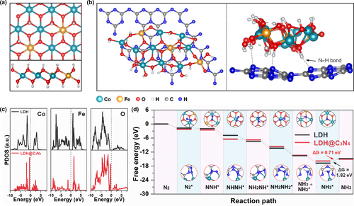
Our interfacing strategy to enhance the nitrogen adsorption and reduction activities was theoretically validated by DFT calculations. To simulate the LDH surface, a two-layer model of Co(OH)2 with 4 × 4 supercell was built up at first, and four iron atoms were used to replace four exposed cobalt atoms to construct the LDH surface with a Co/Fe mol ratio of 3:1. Besides, two H+ were removed to simulate the influence of and H2O, as shown in Figure 1a. To explore the role of coupled heterointerface between LDH and g-C3N4, a new model was built up in which one layer of g-C3N4 was superposed on the LDH surface (Figure 1b), similar to the case of MXene and LDH.[46] Based on these structural models, the projected density of states (PDOS) was calculated and shown in Figure 1c. As seen from this figure, LDH@C3N4 exhibits a smaller bandgap, suggesting that the electronic conductivity of LDH is improved to some extent after forming a coupled heterointerface with g-C3N4. The adsorption properties of LDH and LDH@C3N4 toward nitrogen and ammonia are key factors to evaluate their NRR performances. As shown in Figure S1, Supporting Information, LDH@C3N4 exhibits a higher binding energy toward nitrogen than LDH, indicating the former is more prone to adsorbing nitrogen molecules, which is a prerequisite for the following reduction process. On the other hand, the binding energy of LDH@C3N4 toward ammonia is much lower than that of LDH, meaning the produced ammonia is liable to be desorbed from the former, and would not occupy the active sites to poison the catalyst system. As such, the stronger tendency of LDH@C3N4 to adsorb nitrogen and release ammonia endows it with better electrocatalytic properties. Moreover, the binding structures are shown in Figures S2 and S3, and the binding energies are listed in Table 1. Note that except for NH2NH2 on LDH@C3N4 (with a binding energy of only –0.59 eV), the binding energies of other reaction intermediates on both LDH@C3N4 and LDH are relatively high (ranging from –1.31 to –3.17 eV), making the conversion of activated nitrogen possible. However, NNH2 is easy to dissociate from LDH and form NNH and H, which means NNH2 cannot stably exist on the LDH surface, as shown in Figure S4.
| Model | N2 | NNH | NNH2 | NHNH | NH2NH | NH2NH2 | NH2 | NH3 |
|---|---|---|---|---|---|---|---|---|
| LDH | –1.75 | –3.25 | – | –2.33 | –2.69 | –2.60 | –3.17 | –1.82 |
| LDH@C3N4 | –2.15 | –2.63 | –1.31 | –1.81 | –1.82 | –0.59 | –2.89 | –0.71 |
As discussed above, NNH2 is inclined to be decomposed into NNH and H on LDH, and NHNH (–1.81 eV) shows a higher binding energy than NNH2 (–1.31 eV) on LDH@C3N4, which means the enzymatic mechanism (containing the NHNH intermediate) is more favored than the distal mechanism (containing the NNH2 intermediate). Therefore, the enzymatic mechanism on LDH and LDH@C3N4 was simulated to evaluate their electrocatalytic properties for the conversion of activated nitrogen to ammonia. As shown in Figure 1d, all electrochemical steps are downhill in the free energy, and LDH@C3N4 exhibits a lower desorption energy than LDH (0.71 vs. 1.82 eV). Additionally, the total density of states (TDOSs) was also calculated, as shown in Figure S5. Compared with that of LDH, the TDOS of LDH@C3N4 shows a smaller gap near the Fermi level, which means that LDH@C3N4 has a smaller bandgap than LDH. Based on our calculation results, interfacing LDH with g-C3N4 is indeed able to enhance its ability toward nitrogen adsorption and reduction, as will be proven by the experimental results.
2.2 Synthesis and Characterization of LDH@C3N4@TiO2 NM
The field-emission scanning electron microscopy (FE-SEM) images of TiO2, C3N4@TiO2, and LDH@C3N4@TiO2 NMs are shown in Figure 2a and Figure S6. It can be seen that the pristine TiO2 NM is composed of randomly packed nanofibers whose average diameter is ˜270 nm, and is featured by an interconnected 2D network (Figure S6a). After in situ polymerization of gaseous melamine molecules, the adjacent nanofibers are obviously adhered owing to the formation of an ultrathin g-C3N4 layer on the nanofiber surface (Figure S6b). Compared with the TiO2 and C3N4@TiO2 nanofibers, the LDH@C3N4@TiO2 nanofibers have remarkably increased diameters. Different from the smooth surface of the TiO2 and C3N4@TiO2 nanofibers, needle-like Co-Fe LDH nanoarrays with lengths of several micrometers are observed perpendicular to the nanofiber surface (Figure 2a and Figure S6c), indicating the successful growth of a secondary structure on the self-standing substrate, as schematically illustrated in Figure 2b. The X-ray diffraction (XRD) patterns (Figure 2c) were collected to distinguish the crystalline phase evolution. It is found that three kinds of phases exist in the LDH@C3N4@TiO2 NM. The (101), (004), (200), (105), (211), and (204) planes situated at 25.3°, 37.8°, 48.0°, 53.9°, 55.1°, and 62.7° are consistent with the XRD data of anatase TiO2 (JCPDS no. 21–1272).[47] The diffraction peak located at 27.4° is indexed to the (002) plane of g-C3N4 (JCPDS no. 87–1526).[48] The diffraction peaks present at 11.6°, 34.1°, 35.1°, and 38.7° correspond to the (003), (012), (009), and (015) planes of Co-Fe LDH (JCPDS no. 50–0235).[31]
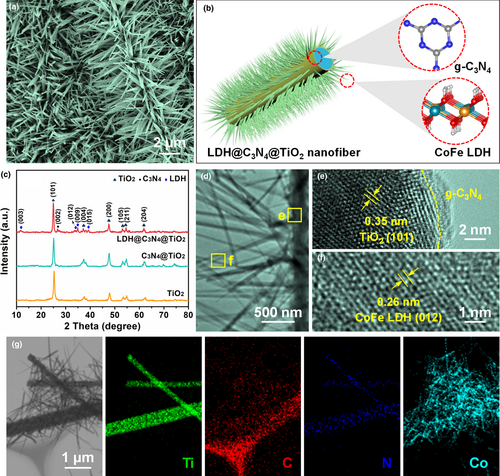
Transmission electron microscopy (TEM) was employed to reveal the fine structure of LDH@C3N4@TiO2. As shown in Figure 2d, the Co-Fe LDH nanoneedles grew evenly and densely on the surface of the C3N4@TiO2 nanofiber and were well retained after the sonication process for preparing the TEM sample, suggesting that the interfacial interaction between the Co-Fe LDH nanoneedles and the g-C3N4 layer was strong enough. Closer observation of the LDH@C3N4@TiO2 nanofiber under high-resolution TEM (HRTEM) indicates that the substrate is composed of intimately connected TiO2 nanofiber and a g-C3N4 layer with a thickness of only ˜2 nm (Figure 2e), which shows a good match with the TEM and HRTEM images of the C3N4@TiO2 nanofiber (Figure S7a,b). As shown in Figure 2f, the TEM image focusing on a single nanoneedle displays a lattice fringe spacing of 0.26 nm assigned to the (012) plane of Co-Fe LDH.[49] The scanning transmission electron microscopy (STEM) image and the corresponding elemental maps obtained from a single C3N4@TiO2 nanofiber manifest that the carbon and nitrogen elements present homogeneous distributions on the surface of the TiO2 nanofiber, which also provide evidence for the successful coating of an ultrathin g-C3N4 layer (Figure S7c). The content of the ultrathin g-C3N4 layer in the C3N4@TiO2 NM, as determined by thermal gravimetric analysis (TGA), is 12.32 wt% (Figure S8). As for the LDH@C3N4@TiO2 nanofiber, the elemental maps of titanium, carbon, and nitrogen draw a fibrous outline, matching well with the morphology of the C3N4@TiO2 nanofiber (Figure 2g). The distribution of cobalt, as a representative element of Co-Fe LDH, is also revealed in Figure 2g, which is in good agreement with the nanoneedles standing on the surface of the C3N4@TiO2 nanofiber. According to the energy dispersive X-ray spectroscopy (EDS) spectrum (Figure S9), the cobalt and iron contents in the LDH@C3N4@TiO2 NM are 19 and 5.7 wt%, respectively, which are consistent with their feed ratios, demonstrating that the Co-Fe LDH nanoneedles were facilely synthesized through one-step epitaxial growth.
Since the electrolyte permeability has an important effect on the electrocatalytic performance, the nitrogen adsorption–desorption isotherms of TiO2, C3N4@TiO2, and LDH@C3N4@TiO2 NMs were collected to reveal their pore structures (Figure S10, Supporting Information). It is easy to find that all the curves match well with type IV adsorption isotherms, where a series of adsorption behaviors including monolayer adsorption, multilayer adsorption, and capillary condensation are displayed, indicating that mesopores exist within the NMs. Based on the above curves, the Brunauer–Emmett–Teller (BET) surface areas of TiO2, C3N4@TiO2, and LDH@C3N4@TiO2 NMs are determined, being 38.95, 22.08, and 34.29 m2 g−1, respectively. It is noteworthy that the C3N4@TiO2 NM shows a smaller surface area than the TiO2 NM, which is attributed to the intimate contact between the ultrathin g-C3N4 layer and the TiO2 nanofibers. Interestingly, the surface area of the LDH@C3N4@TiO2 NM increases to a value comparable to that of the TiO2 NM, revealing the significant effect of the Co-Fe LDH nanoneedles on improving the porous structure of the designed catalyst system. Another important feature of the LDH@C3N4@TiO2 NM is its robustness and flexibility. As shown in the inset of Figure S11, Supporting Information, the LDH@C3N4@TiO2 NM could withstand a bending test of approximately 90° and return to the initial shape without obvious deformation. The tensile stress–strain curve in Figure S11, Supporting Information indicates that the LDH@C3N4@TiO2 NM possesses a strength up to 810 kPa. In contrast to the traditional substrate (e.g., nickel foam) that was brittle after the solvothermal reaction, the LDH@C3N4@TiO2 NM has the advantages of convenient usage and excellent stability.[31]
The X-ray photoelectron spectroscopy (XPS) data of the LDH@C3N4@TiO2 NM were collected to figure out the valance states of the elements. The wide-scan survey spectrum in Figure 3a shows that the titanium, oxygen, carbon, nitrogen, cobalt, and iron elements are present in the sample. Figure 3b shows the Ti 2p spectrum, and the two separate peaks situated at 464.6 and 458.8 eV are assigned to Ti 2p1/2 and Ti 2p3/2 orbitals, respectively.[44] The O 1s spectrum in Figure 3c is deconvoluted into three spin-orbit peaks, of which the one located at 529.0 eV is indexed to lattice oxygen (Ti–O),[44] the one at 530.9 eV is ascribed to the –OH group,[50] and the one at 531.3 eV comes from the O–C=O bond in Co-Fe LDH.[31]
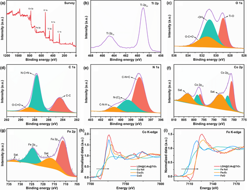
As can be seen in Figure 3d, three isolated peaks at 284.4, 287.7, and 288.7 eV are deconvoluted from the C 1s spectrum, corresponding to the C–C bond in surface adventitious carbon, the N–C=N bond in g-C3N4, and the O–C=O bond in Co-Fe LDH, respectively.[31, 51] The N 1s spectrum in Figure 3e is fitted into three peaks located at 398.1, 399.3, and 400.7 eV, which are ascribed to C–N=C, N–(C)3, and C–N–H, respectively.[52] In the Co 2p spectrum (Figure 3f), both Co 2p3/2 and Co 2p1/2 can be fitted into two spin-orbit peaks, indicating the presence of two states of cobalt element in the LDH@C3N4@TiO2 NM. In the Co 2p3/2 peak, the two deconvoluted peaks located at 781.2 and 783.2 eV are assigned to Co3+ and Co2+, along with a satellite peak at 786.8 eV. As for the Co 2p1/2 peak, it can be fitted into two peaks located at 796.9 and 798.3 eV that correspond to Co3+ and Co2+, and a satellite peak at 803.1 eV.[53] The Fe 2p XPS spectrum in Figure 3g can be deconvoluted into two main peaks at 711.2 and 724.6 eV which are ascribed to Fe 2p3/2 and Fe 2p1/2 orbitals, and two satellite peaks at 716.4 and 732.8 eV, confirming the existence of Fe3+ in the sample.[54] In order to further investigate the chemical states of Co and Fe in the LDH@C3N4@TiO2 NM, X-ray absorption near edge structure (XANES) at Co and Fe K-edge was measured (Figure 3h,i). The absorption edge energy of Co K-edge in the LDH@C3N4@TiO2 NM (7722.75 eV) is higher than that in Co foil (7709 eV) and CoO (7721.37 eV), whereas lower than that in Co2O3 (7728.19 eV), verifying the coexistence of Co2+ and Co3+. Similarly, it also could be found that the absorption edge energy of Fe K-edge in the LDH@C3N4@TiO2 NM (7116.34 eV) is higher than that in Fe foil (7112.05 eV) and FeO (7114.78 eV), and very close to that in Fe2O3 (7116.30 eV), demonstrating that the valence state of Fe is +3 and this echoes the Fe 2p XPS result.
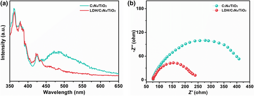
To explore the effect of interfacial coupling between g-C3N4 and Co-Fe LDH, the PL spectrum of the LDH@C3N4@TiO2 NM is compared with that of the C3N4@TiO2 NM, as shown in Figure 4a. Note that the former exhibits a lower photoluminescence (PL) intensity, once again proving that the facilitated interfacial charge transfer between Co-Fe LDH and g-C3N4. This phenomenon was further confirmed by electrochemical impedance spectroscopy (EIS) (Figure 4b), in which the LDH@C3N4@TiO2 NM displays a much smaller diameter of the semicircle than the C3N4@TiO2 NM, corresponding to a lower charge transfer resistance.
2.3 Electrocatalytic NRR Performance of LDH@C3N4@TiO2 NM
To test the NRR performance of the LDH@C3N4@TiO2 NM, it was used as a self-standing working electrode in an H-type electrolytic cell. Before the NRR tests, the cathodic compartment was bubbled with 99.999% nitrogen for at least 30 min to dispel the air in the electrolyte, and argon or nitrogen was introduced in the successive step. The linear sweep voltammetry (LSV) results are presented in Figure S12, Supporting Information, which discloses an obvious difference in the current between the two feed gases, suggesting possible NRR in the nitrogen atmosphere. Motivated by this result, the LDH@C3N4@TiO2 NM was further subjected to electrolysis in nitrogen at different potentials (–0.45 to –0.75 V vs. RHE) for 2 h, and the chronoamperometric curves are presented in Figure 5a, which provide the information on the total quantities of applied charge at these potentials. The electrolytes after electrolysis were subjected to the indophenol blue method, by which the absorbance at 662 nm can be linearly correlated to the ammonia concentration (Figure S13, Supporting Information).[20] Accordingly, the absorbance of the electrolyte at each potential is shown in Figure 5b, from which we can see the highest absorbance occurs at –0.55 V vs. RHE. A decreased absorbance occurs at higher potential, which probably arises from a stronger competition from the hydrogen evolution reaction. Based on the chronoamperometric curves and UV-vis absorption spectra, the ammonia yield and Faradaic efficiency are obtained and given in Figure 5c. As seen from this figure, the highest ammonia yield comes from –0.55 V vs. RHE, being 2.07 × 10⁻⁹ mol s−1 cm−2, while the highest Faradaic efficiency comes from –0.45 V vs. RHE, being 25.3%. Note that these values are significantly higher than those of the TiO2 (0.45 × 10⁻⁹ mol s−1 cm−2) and C3N4@TiO2 (0.72 × 10⁻⁹ mol s−1 cm−2) NMs, confirming the prominent synergistic effect of the three components (Figure 5d and Figure S14, Supporting Information). Moreover, the NRR performance of the LDH@C3N4@TiO2 NM was compared with some other noble-metal-free electrocatalysts ever reported based on LDH, g-C3N4, TiO2, etc., and it is found to surpasses most of these electrocatalysts (Table S1, Supporting Information), demonstrating the effectiveness of remarkable interfacial effect and unique structural design in our catalyst system.
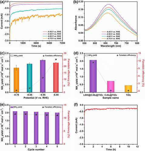
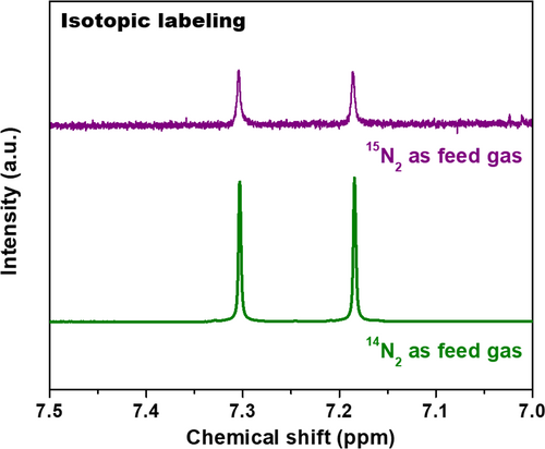
It is known that the repeatability and long-term durability are crucial parameters for an electrocatalyst. As such, the LDH@C3N4@TiO2 NM underwent a cycling experiment in which it was repeatedly electrolyzed in nitrogen at –0.55 V vs. RHE for five times (each time 2 h). The indophenol blue method was used to determine the ammonia contents in the electrolytes, and the ammonia yields along with Faradaic efficiencies are presented in Figure 5e. It is seen that only a tiny fluctuation occurs with regard to ammonia yield as well as Faradaic efficiency in different cycles, suggesting excellent repeatability and stability of the LDH@C3N4@TiO2 NM. Moreover, it could withstand long-term electrolysis of 12 h with a stable chronoamperometric curve, exhibiting good durability which is of great importance to practical applications (Figure 5f). To verify whether ammonia came from nitrogen by electrocatalysis of the LDH@C3N4@TiO2 NM, it was subjected to electrolysis under open circuit for 2 h. The indophenol blue method was used to test the resultant electrolyte, and the result shown in Figure S15, Supporting Information indicates that no ammonia was detected. Besides, the electrolyte was tested according to the Watt and Chrisp method, which could also correlate the hydrazine concentration with its absorbance at 458 nm linearly (Figure S16, Supporting Information).[20] As seen from Figure S17, Supporting Information, no hydrazine was detected in the electrolyte after being electrolyzed at –0.55 V vs. RHE. Finally, the content in the electrolyte was also detected to be zero, which excludes possible NOx contamination in the feed gas (Figures S18 and S19, Supporting Information). To convincingly get clear the origin of ammonia, the isotopic labeling was conducted since the result of 1H resonance with 15N is totally different from that with 14N.[55] Specifically, two symmetrical peaks with a spacing of 71.4 Hz can be found in the 1H NMR spectrum of a standard sample, as shown in Figure 6. After being electrolyzed with 15N2 as the feed gas at –0.55 V vs. RHE for 12 h, the electrolyte was collected and subjected to 1H nuclear magnetic resonance (NMR) spectroscopy, the result of which is consistent with the standard sample. As such, it can be concluded that the detected ammonia indeed came from nitrogen as catalyzed by the LDH@C3N4@TiO2 NM, since it is hard to introduce 15N-containing contaminants during throughout the whole process.
3 Conclusion
In conclusion, a coupled heterointerface between Co-Fe LDH and g-C3N4 is constructed on a TiO2 NM by in situ polymerization and epitaxial growth. The binding energies of nitrogen and ammonia on LDH and LDH@C3N4 are evaluated through DFT calculations, which reveal that the interfacial effect between Co-Fe LDH and g-C3N4 indeed facilitates the nitrogen adsorption and reduction under ambient conditions. By integrating the unique interface effect and porous structure, the self-standing LDH@C3N4@TiO2 NM delivers superior NH3 yield (2.07 × 10⁻⁹ mol s−1 cm−2 at –0.55 V vs. RHE) and Faradaic efficiency (25.3% at –0.45 V vs. RHE), outperforming most of the noble-metal-free electrocatalysts ever reported, and ranking it as a high-efficiency, noble-metal-free catalyst system toward electrocatalytic NRR.
Acknowledgements
This work was financially supported by the National Natural Science Foundation of China (No. 52173055 and 21961132024), the Natural Science Foundation of Shanghai (No. 19ZR1401100), the International Cooperation Fund of Science and Technology Commission of Shanghai Municipality (No. 21130750100), the Innovation Program of Shanghai Municipal Education Commission (No. 2017-01-07-00-03-E00024), the Fundamental Research Funds for the Central Universities (No. 18D310109), and the DHU Distinguished Young Professor Program (No. LZA2020001).
Conflict of Interest
The authors declare no competing interests.


