Easily Obtaining Excellent Performance High-voltage LiCoO2 via Pr6O11 Modification
Abstract
Developing an effective method to synthesize high-performance high-voltage LiCoO2 is essential for its industrialization in lithium batteries (LIBs). This work proposes a simple mass-produced strategy for the first time, that is, negative temperature coefficient thermosensitive Pr6O11 nanoparticles are uniformly modified on LiCoO2 to prepare LiCoO2@Pr6O11 (LCO@PrO) via a liquid-phase mixing combined with annealing method. Tested at 274 mA g−1, the modified LCO@PrO electrodes deliver excellent 4.5 V high-voltage cycling performance with capacity retention ratios of 90.8% and 80.5% at 25 and 60 °C, being much larger than those of 22.8% and 63.2% for bare LCO electrodes. Several effective strategies were used to clearly unveil the performance enhancement mechanism induced by Pr6O11 modification. It is discovered that Pr6O11 can improve interface compatibility, exhibit improved conductivity at elevated temperature, thus enhance the Li+ diffusion kinetics, and suppress the phase transformation of LCO and its resulting mechanical stresses. The 450 mAh LCO@PrO‖graphite pouch cells show excellent LIB performance and improved thermal safety characteristics. Importantly, the energy density of such pouch cell was increased even by ~42% at 5 C. This extremely convenient technology is feasible for producing high-energy density LIBs with negligible cost increase, undoubtedly providing important academic inspiration for industrialization.
1 Introduction
Up to now, LiCoO2 (LCO) cathode material still occupies an important position in the consumer electronics market due to its ultra-high tap density and volumetric energy density.[1-4] It is reported that increasing the charging cutoff potential, usually larger than 4.4 V corresponding to more than removal amount of 0.6 Li+ in LiCoO2, can effectively improve the energy density of the LCO.[5, 6] However, it will also cause a sharp decline in the cycling performance originated from a series of phase transitions for high-voltage LiCoO2 (H-LCO).[7-9] Herein, the release of surface oxygen and the loss of cobalt ions are other main reasons for the capacity attenuation of H-LCO.[10, 11] Typically, in the low-voltage region, the LCO will undergo the insulator-to-metal phase transition, and the hexagonal structure H-1 phase will gradually transform into hexagonal structure H-2 phase. When the charging voltage reaches 4.2 V, the LCO material delivers a reversible transformation from O3 phase in the R—3m space group to monoclinic structure, and then back to O3 phase, which involves the “order ⇆ disorder” transformation of crystalline phase. In this process, the change in crystal parameters caused by the spatial mismatch between lithium ion and lithium vacancy will lead to the change in particle volume for LCO. Finally, another phase transformation of LiCoO2 from O3 phase to H1-3 phase occurs when charging to above 4.5 V. In these reversible phase transitions, the transformation of “O3 phase ⇆ monoclinic structure” will significantly reduce the Li+ diffusion kinetics, and during the further transformation of “O3 phase → H1-3 phase,” severe mechanical stress and cracks will appear in the bulk material, accompanied by the decrease in Li+ diffusion rate, which leads to the last rapid capacity fading. Thus, overcoming these obstacles is significant for the development of H-LCO materials.
Generally, many strategies have been developed to overcome the cycling stability fading of H-LCO. On the one hand, foreign element doping in bulk phase has been demonstrated to be promising and effective for the improvement of H-LCO LIB performance,[12, 13] which can inhibit the irreversible phase transformation, improve the stability of the phase structure, and alleviate the stress and deformation caused by the structural transformation during the charge/discharge process. For example, Zhao et al. found that Sn4+ doping can inhibit the conversion of LCO to spinel phase under high potential due to the decrease in the thermal movement of atoms, thus boosting cycling stability. Meanwhile, different elements of co-doping are commonly carried out in LCO modulation.[14-16] On the other hand, the surface modification with electronic/ionic conductor and oxide materials improves the interface stability between H-LCO and electrolyte, suppresses the degradation of interface, and generates appropriate cathode electrolyte interphase (CEI) film to obtain stable cycling performance.[17-19] Herein, the surface modification can also adjust the local electronic structure of the H-LCO and the microstructure of the particle surface, and then regulate the ionic/electronic conductivity of the material, reduce the polarization, and finally elevate their LIB performance. Recently, Cho’s group developed a high-temperature Ni doping strategy for improving the performance of H-LCO.[20] Interestingly, it is reported that Ni doping can inhibit phase transformation in cycling processes, but it does not constitute the main contribution for enhanced LIB performance; on the contrary, the stable surface-modified layer formed by the surface segregation of Ni after doping is the main reason for the improvement of the cycling properties. It is concluded that surface modification plays a pivotal role in the LIB performance modulation for H-LCO. Therefore, effective surface modification will undoubtedly simplify the route and reduce the costs for the industrial production of high-performance H-LCO.
In fact, there are many advanced H-LCO materials with varied charging cutoff potentials, and much progress has been made to improve their performance.[21-23] However, in addition to voltage and capacity fading, these H-LCO materials still face significant issues including thermodynamic instability and thermal safety problems, limited their commercialization. Herein, in terms of LCO thermal safety during high-voltage charging, the released oxygen ions from LCO generate highly oxidizing free radicals in the electrolyte, and a series of side reactions occur on the LCO surface, resulting in the formation of thicker CEI passive film, and further increasing the interface impedance and ohmic heat, especially at elevated temperatures.[24] Among many strategies for LIB thermal safety modulations, introducing positive temperature coefficient (PTC) materials is an effective way.[25] From the perspective of electrochemistry, the PTC material introduction can establish a self-excited heating protection mechanism in LIBs, directly cut off the internal short circuit between cathodic and anodic electrodes at high temperature and turn off the battery reaction, so as to prevent the spread of thermal runaway in LIBs. A series of new thermal runaway prevention technologies have been proposed in recent years, including PTC electrode,[25] thermosensitive microspheres modified membrane,[26] and thermal polymerization additives,[27] etc. On the contrary, introducing negative temperature coefficient (NTC) materials such as the well-known Pr6O11,[28] TaN,[29] and SnSe,[30] into LIB electrodes, it is predicted that the conductivity of the electrode can be enhanced reversely at high temperature, so as to reduce the polarization and ohmic heating, and finally improve the thermal safety of LIBs. In particular, introducing NTC material of Pr6O11 can deliver two obvious advantages. On the one hand, Pr6O11 nanoparticles were uniformly modify commercial L-LCO for obtaining H-LCO, effectively achieving good electron conductivity at elevated temperature, and further solving the sluggish reaction kinetics and poor thermal safety performance of H-LCO cathodes for LIBs. On the other hand, similar to the surface modification of other metal oxides, NTC material of Pr6O11 as a surface modification on H-LCO should be able to inhibit the corrosion of electrolyte side reaction on the electrode material and further improve the modification effect of the material. Unfortunately, the related design has not been reported to adequately address so far, especially in the development of H-LCO cathodes.
Therefore, it is highly needed to develop H-LCO materials with excellent conductivity and stable interface compatibility, which can improve the LIB performance including thermal safety performance at room temperature and high temperature. More importantly, based on the consideration of effective connection between basic research and industrial application, developing a simple mass-produced strategy for H-LCO materials and achieving their comprehensive LIB performance evaluation in practical pouch full cells are widely expected by researchers.
Inspired by the issues above mentioned, for the first time, this work proposes a simple hectogram-grade produced approach, that is, NTC material of Pr6O11 was uniformly modified on commercial LCO to prepare LCO@PrO via a liquid-phase mixing combined with annealing method. The obtained LCO@PrO electrodes deliver excellent 4.5 V high-voltage cycling LIB performance at 25 and 60 °C, both much better than bare LCO electrodes. In addition, the assembled 450 mAh LCO@PrO‖graphite pouch cells deliver excellent LIB performance and thermal safety characteristics under 3.0–4.45 V, which energy density increased even by 41.8% at 5 C compared with LCO‖graphite pouch cells. The performance enhancement mechanism induced by Pr6O11 modification was also clearly unveiled, offering important new insights and valuable electrode design concepts that are beneficial for LIBs. Moreover, this extremely convenient technology is feasible for producing high-energy density LIBs with negligible cost increase, undoubtedly providing important academic inspiration for H-LCO industrial production.
2 Results and Discussion
2.1 Morphology and Structure
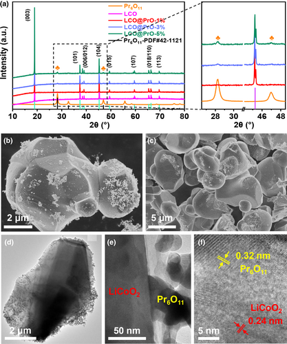
The crystalline structure of the materials for LCO, LCO@PrO-1%, LCO@PrO-3%, and LCO@PrO-5% was detected by XRD. As shown in Figure 1a, all the samples deliver evident R—3m space group with the α-NaFeO2 crystal layered structure located in peaks of 18.68°, 36.72°, 37.88°, 38.37°, 44.46°, 48.62°, 58.63°, 64.36°, 65.02°, and 69.70°, corresponding to diffraction planes of (003), (101), (006), (012), (104), (015), (107), (018), (110), and (113), respectively,[31-33] and Pr6O11 the diffraction degree of Pr6O11 is highly consistent with standard card PDF#42-1121.[34, 35] Notably, the result reveals that the modified Pr6O11 nanoparticles (NPs) have no influence on the crystalline structure of LCO materials. Meanwhile, the main peak intensity at 28.3° and 46.9° for Pr6O11 becomes more prominent with its content in LCO increased from 1% to 5%, as shown in the magnification section. Additionally, from Figure 1b–d and Figure S2a–c, Supporting Information, it is clearly seen that the Pr6O11 NPs are uniformly distributed on the surface of LCO, being different from bare LCO material. It can also be found from Figure S2b,c, Supporting Information that the number of Pr6O11 NPs coated on LCO increased significantly with the increase in Pr6O11 content. Furthermore, as displayed in Figure 1e,f, the high-resolution transmission electron microscopy (HR-TEM) images show typical lattice spaces of 0.24 and 0.32 nm in the core and modified region originating from the LCO (101) and Pr6O11 (111) planes.[35, 36] Simultaneously, the XPS signals of Pr 3d for LCO and LCO@PrO-1% samples compared in Figure S2d, Supporting Information reveal the existence of Pr6O11 in LCO@PrO material. As illustrated in Figure S3, Supporting Information, the element mapping further demonstrates that Pr element is evenly dispersed, also distinctly verifying that Pr6O11 is successfully and uniformly coated on the surface of LiCoO2. As can be seen in Table S4, Supporting Information, the Pr6O11 mass ratio in LCO@PrO-1%, LCO@PrO-3%, and LCO@PrO-5% powers is 0.92%, 2.83%, and 4.76%, respectively, and the lost mass may be ascribed to washing in synthetic process. In addition, as displayed in Figure S4a, Supporting Information, the XPS full spectrum for samples of LCO and LCO@PrO-1% shows the peaks of Li 1s, C 1s, O 1s, Co 2p, and Pr 3d. Figure S4b–d, Supporting Information shows the high-resolution spectrum of Li 1s, O 1s, and Co 2p, respectively.
2.2 Electrochemical LIB Performance
To demonstrate the Pr6O11 modified superiority for LCO, the cycling performances of LCO, LCO@PrO-1%, LCO@PrO-3%, and LCO@PrO-5% were tested as cathode materials in the voltage range of 3.0–4.5 V for LIBs. As can be found in Figure 2a, under room temperature (RT), these four samples were tested at 1 C (i.e., 274 mA g−1) current density for 100 cycles, obviously demonstrating that the modified LCO@PrO-1% electrode possesses superior and impressive cycling stability with higher reversible capacity and capacity retention (166.6 mAh g−1, 90.6%) than those of LCO (43.8 mAh g−1, 22.8%), LCO@PrO-3% (144.7 mAh g−1, 81.8%), and LCO@PrO-5% (142.6 mAh g−1, 81.9%). In addition, as shown in Figure S5, Supporting Information, the modified material expresses more stable coulombic efficiency. The compared results indicate the enhanced cycle performance can be obtained via Pr6O11 NPs modification. Meanwhile, the charge–discharge curves at the first cycle and 50th cycle of four electrodes are demonstrated in Figure 2b. During the first cycling process, two main voltage platforms for samples are located at ~4.4 and ~4.0 V, respectively. The redox potential at ~4.4 V might originate from the transformation of hexagonal phase to H2 monoclinic phase, and the long platform near 4.0 V is mainly the transformation between two O3 phases. Remarkably, the voltage platforms of modified LCO electrodes have rarely changed at ~4.0 V after 50 cycles, while that of bare LCO disappears, indicating that the irreversible phase transformation and the severe structural degradation have occurred in bare LCO material. Figure 2c displays rate performance of these four electrodes tested from 0.1 to 5.0 C. In the case of bare LCO sample, its reversible capacity urgently decreased with the elevated current density, suggesting possible electrode polarization and unstable interface compatibility. On the contrary, three modified LCO@PrO electrodes deliver much better rate stability compared with bare LCO. Notably, the LCO@PrO-1% electrode can deliver highly reversible specific capacities of 184.8 and 152.4 mAh g−1 at the current densities of 0.1 and 5.0 C, respectively. When the current density returns to 0.1 C after 25 cycles, the capacity of LCO@PrO-1% can recover to 176.0 mAh g−1 with large capacity retention of ~97%. More details can be seen in Figure S6, Supporting Information. Herein, the corresponding cycle curves under varied current densities shown in Figure S7a–d, Supporting Information also displays that LCO@PrO-1% possesses the lowest polarization and the most stable voltage plateau among the four samples. The above results show that the LCO material modified with 1.0 wt.% Pr6O11 has the best comprehensive LIB performance.
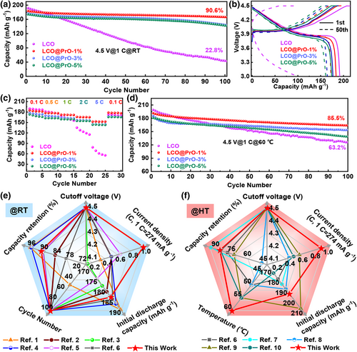
The effect of the enhanced conductivity from the NTC material of Pr6O11 at high temperature on LIBs needs to be evaluated. Figure 2d compares the high-temperature cycling performance at 60 °C for electrodes of LCO, LCO@PrO-1%, LCO@PrO-3%, and LCO@PrO-5%. In comparison, LCO@PrO-1% electrode demonstrates the best cycling performance, showing a reversible capacity of 163.8 mAh g−1 after 100 cycles with capacity retention of 85.5%. However, the capacity retention of bare LCO is only 67.3%, which may be related to serious side effects and the violent dissolution of transition metal ions in the electrolyte happened in the active material. Herein, as shown in Figure S8, Supporting Information, the modified material expresses more stable coulombic efficiency under 60 °C, which is similar to room temperature. Furthermore, as shown in Figure S9, Supporting Information, the electronic conductivity of bare LCO and LCO@PrO-1% was tested at elevated temperature from 0 to 70 °C. As can be seen, the conductivity of bare LCO material is ~4.4 * 10−5 S cm−1 under 0 °C, being similar to previous report.[37] Significantly, as displayed in Figure S9b, Supporting Information, with increased temperature, the electrical conductivity for modified LCO increases evidently from 1.2 * 10−4 to 2.8 * 10−4 S cm−1, while the bare LCO sample increases from 4.4 * 10−5 only to 8.4 * 10−5 S cm−1. These results reveal that Pr6O11 coating is beneficial to promoting the electrical conductivity of the LCO active material especially at elevated temperatures, being worthy of expectation for improving the electrical properties of the material. As shown in Figure 2e,f, it is worth mentioning that the LCO@PrO-1% delivers great improvement of the comprehensive LIB performance including initial discharge capacity, capacity retention, and cycling number etc., compared with recently reported LCO-based cathodes. More compared details can be seen from Tables S5 and S6, Supporting information. Being similar to some previous reports,[17, 19, 38] our results have proved that the Pr6O11 surface modification can effectively enable the conventional LCO to store lithium ions at high voltage of 4.5 V. As shown in Figure S10, Supporting Information, Pr6O11 modification can also boost the LIB performance of LCO at normal charging cutoff potential of 4.3 V. More importantly, the high-temperature LIB performance is an important investigated factor for LCO practical application. More importantly, it is well known that further increasing the charging cutoff potential of LCO to >4.5 V, such as 4.55 and 4.6 V, can more effectively improve the energy density of LCO, which is eagerly expected by many researchers. As expected, Figure S11, Supporting Information shows that the obtained LCO@PrO-1% composites deliver obvious improvement of the comprehensive LIB performance at further elevated charging cutoff potentials of 4.55 and 4.6 V, compared with bare LCO cathodes without PrO-modification. More experimental details and discussions have been displayed in supporting information.
Thus, the excellent LIB performance of LCO@PrO-1% electrodes at both of varied temperatures (i.e., RT and 60 °C) and different charging cutoff potentials (i.e., 4.3, 4.5, 4.55, and 4.60 V) may be attributed to the improved interface compatibility, the enhanced conductivity at elevated temperature, the fast Li+ diffusion kinetics, and the suppressed phase transformation as well as mechanical stresses at high voltage, due to effective Pr6O11 modification, which will be discussed in the following.
2.3 Discussion for the Performance Enhanced Mechanism
The above-discussed results reveal that surface decoration with Pr6O11 has been demonstrated to be an effective method for improving the LIB performance of LCO, but the improved mechanism still lacks understanding. Several effective test and analysis strategies were used to clearly unveil the performance enhancement mechanism induced by Pr6O11 modification, concerning conductivity, morphologies, polarization behavior, interface compatibility, Li+ diffusion kinetics, and crystal phases and so on.
The CEI film on the cathode surface is thermodynamically formed by the alignment of the oxidation energy level of the electrolytes and the Fermi level of the cathode surface.[39] The surface electronic structure of cathode can determine the redox kinetic of electrolyte and further affect the formation and composition of CEI. Therefore, Kelvin Probe Atomic Force Microscope (KPFM) measurements were performed to obtain effective work functions of materials, which affects the stability and formation for CEI. Figure S12, Supporting Information displays the surface potential and morphology images of Pr6O11, LCO, and LCO@PrO-1% measured by KPFM. The work functions presented in Figure 3a for each sample were further calculated from these surface potential maps. Interestingly, as shown in Figure 3a, the Pr6O11 and LCO samples deliver work function of approximately 5.45 and 5.53 eV, respectively, while lower value of work function (~5.24 eV) can be obtained for the LCO@PrO-1% due to the existence of interface charge transport. To further understand the relationship between temperature and conductance, the KPFM test was utilized to measure the work function of the materials under varied temperatures. As demonstrated in Figure S13, Supporting Information, it is obvious that the values of work function for bare LCO and modified LCO decrease with the increased temperature, delivering the corresponding values are 5.46, 5.18, and 5.04 eV and 5.18, 4.89, and 4.55 eV under 30, 50, and 70 °C, respectively. The above-obtained results are agreed with the results of the conductivity test. Compared to LCO@PrO-1%, it is revealed from the energy level diagram in Figure 3b that the LCO with the higher value for surface work function would induce higher oxidation kinetic on the cathode/electrolyte interface and further stimulate the CEI film formation occurring on the cathode surface. This conclusion can be well supported by the EIS, XPS, and SEM measurements in the following.
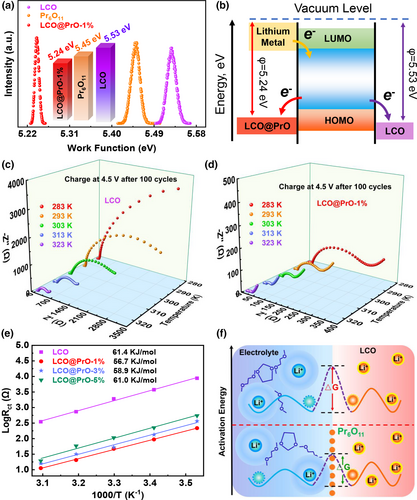
Subsequently, the EIS tests in the range of 0.01 Hz–100 kHz of bare LCO and LCO@PrO electrodes were carried out at different temperatures to get insight into the mechanism of Pr6O11 modification for boosting the charge transport behavior at the electrode/electrolyte interface, which is demonstrated in Figure 3c,d and Figure S14a,b, Supporting Information. Typically, the overall shape of EIS result consists of two depressed semicircles at high-/middle-frequency region and a sloped line in the low-frequency region. Combined with the equivalent circuit in Figure S14c, Supporting Information, it is considered that the intercept between the first semicircle and the transverse axis represents the electrolyte solution resistance of Rs, and the Rsf and Rct are assigned to the resistances of Li+ diffusing through interface CEI film and the transfer resistance at the electron/ion conduction junction, and Wo is the diffusion resistance of Li+ in the bulk phase of the active material in the low-frequency region.[40, 41] Based on the fitted equivalent circuit, the fitting resistance values of each part for varied electrodes at different tested temperatures were summarized in Figure S15a,b, Supporting Information. It can be found that the resistance values of all electrodes become obviously lower as the tested temperature increases, implying the enhanced reaction kinetics and Li ion diffusion speed at higher temperature. In temperature range of 10–50 °C, the values of Rct, Rsf and Rs delivered for bare LCO electrode are always higher than three modified LCO electrodes, suggesting Pr6O11 modification can restrain the side reaction between electrode and electrolyte. The continuous formation of CEI film in bare LCO electrode will inevitably reduce interface compatibility and battery cycle performance, which results are also confirmed by the above battery test. More strikingly, for the comparison of three LCO@PrO samples, the smallest Rct and RSEI values for LCO@PrO-1% electrode reflect the best electron transfer in bulk material and confirm the suppression of CEI film formation because of the suitable Pr6O11-incorporation. Hereinto, the results for above-discussed SEI growth are also supported by the following XPS etching analysis.
Figure 4a,b and Figure S16a,b, Supporting Information show the cyclic voltammetry curves (CVs) of bare LCO and modified LCO@PrO electrodes under the scanning speed of 0.01 mV s−1. It can be found that all electrodes exhibited similar phase-transition peaks for the first five CV cycles. Herein, the peaks near ~4.0 V are ascribed to the transition of two O3 phases, and the peaks located between 4.2 and 4.4 V correspond to the order–disorder transition of “O3 phase ⇆ H1-3 phase,” being consistent with the above charge–discharge profiles and previous reports.[10, 43] Significantly, the redox potential differences between the anodic and cathodic peaks are closely related to the dynamic behavior and polarization of electrode material. Compared with the potential difference (ΔV) of 211 mV for bare LCO, the Pr6O11 modified LCO electrodes deliver the lower ΔV values of 139, 143, and 159 mV, respectively. The ΔV value for bare LCO electrode became larger in the following cycles, suggesting the larger polarization. Instead, the most stable redox peaks appearing in LCO@PrO-1% electrode in the following cycles illustrate that appropriate modification of Pr6O11 on the surface of LCO material can effectively ameliorate dynamic behavior. Simultaneously, as exhibited in Figure 4c,d and Figure S17a,b, Supporting Information, the first and 50th dQ/dV profiles converted from the charge–discharge curves shown in Figure 2b demonstrate that three distinct phase transitions occur at ~4.05, ~4.15, and ~4.47 V versus Li/Li+, being similar to the CV results at the 1st cycle. It should be noted that the dQ/dV profile of bare LCO electrode at the 50th cycle has become weak and disordered. This phenomenon obviously reveals that Pr6O11 modification can mitigate voltage attenuation and suppress the phase transition during cycling, thus enhancing structural stability and energy storage retention.
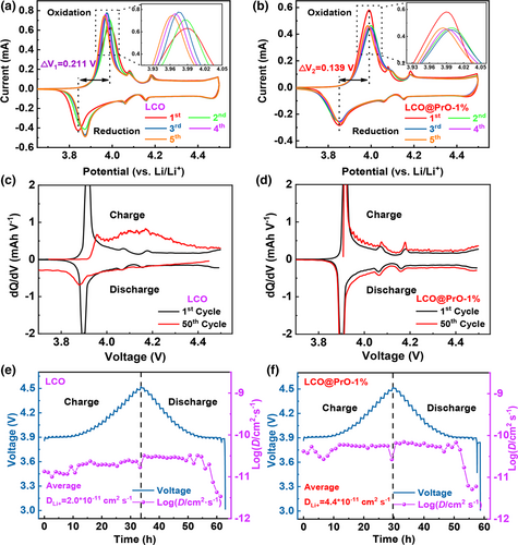
To further investigate the effect of Pr6O11 modification on Li+ transfer behavior in electrodes, Galvanostatic Intermittent Titration Technique (GITT) tests were carried out and used to calculate the lithium ion diffusion coefficient (DLi+), as compared in Figure 4e,f and Figure S18a,b, Supporting Information. The calculated details of GITT processes for these four samples have been displayed in Figure S19, Supporting Information. It is apparent that the calculated values of DLi+ for LCO@PrO-1%, LCO@PrO-3%, and LCO@PrO-5% electrodes are 4.4 * 10−11, 3.4 * 10−11, and 2.3 * 10−11 cm2 s−1, much larger than that of 2.0 * 10−11 cm2 s−1 for bare LCO electrode. Significantly, similar to the result of KPFM, EIS, and CVs analysis, the GITT result also proves that the promoted lithium ion diffusion dynamic originated from Pr6O11 modification can exhibit more superior electrochemical performance at high voltage compared with bare LCO electrode.
To determine the influence of Pr6O11 modification on the interface stability and CEI composition evolution of different cathodes, XPS etching analysis was performed on bare LCO and LCO@PrO-1% electrodes after 100 cycles at 1 C and 60 °C. Herein, XPS etching was operated under Ar+ ion bombardment at 500 eV, accompanied with an etching time of 70 s for each layer of different electrodes. The etching operation for electrode is performed according to the etching rate of 0.03 nm s−1 of standard Ta2O5 in the instrument. Interestingly, the survey XPS spectra displayed in Figure S20, Supporting Information reveals that the Co 2p peaks of bare LCO show weaker intensity than modified LCO, indicating more CEI film covered on the surface of electrode. Figure 5a,b compared the O 1s XPS for bare LCO and LCO@PrO-1% electrodes, respectively. Without etching, the surface of CEI films both contains electrolyte oxidation ROCO2Li and so on. With the increase in etching time, the lattice O signals (529.5 eV) appear in both electrodes, directly providing the physical evidence where the CEI ends in the surface of electrode. It is observed that the lattice O signals in LCO@PrO-1% appear in the etching time at ~70 s, while the bare LCO delivers a longer etching time of ~210 s. Herein, the lattice O signal of LCO@PrO-1% is stronger than the bare LCO during etching processes, indicating that less CEI products appear on the surface of the LCO@PrO-1%. According to the XPS etching analysis for O 1s signals, it is concluded that Pr6O11 modification can establish a more stable and thinner CEI layer, not only being beneficial to the reduction in electrode/electrolyte side reactions and the formation of excellent interface compatibility, but also prompting the improvement of LIB performance for LCO at high voltage.
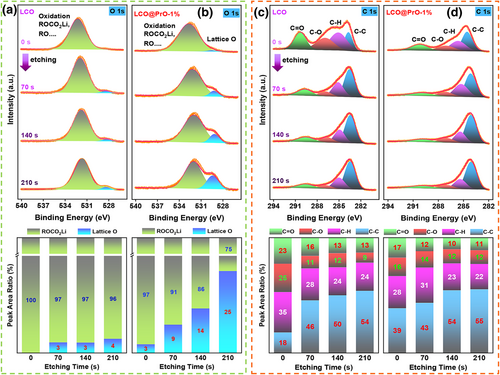
To further prove the above conclusion that more side reactions appear and continuous CEI formation from electrolytes decomposition during cycling process for bare LCO without Pr6O11 modification. As shown in Figure 5c,d, the etching analysis of C 1s XPS for these two electrodes shows the predominant peaks assigned to C-C (~284 eV), C-H (~285 eV), C-O (~287 eV), and C=O (~290 eV) bonds. Herein, the signals from the sp2 and sp3 for C-C and C-H bonds generally represent the binder and conductive carbon black in the electrodes, whereas C-O and C=O bonds can be mainly classified as the decomposition of carbonate electrolyte solvents and the formation of CEI film, especially containing Li2CO3 species that hinder the transport of electric charges or ions.[44] From the varied etching XPS combined with the calculated result of element bonds ratio, it is clear that the intensity of C=O bond for bare LCO cathode can remain more obvious than the modified LCO cathode during etching processes, suggesting that a thicker CEI film mainly containing Li2CO3 species appears in LCO electrode. Furthermore, as revealed in Figure S21, Supporting Information, the high-resolution XPS peaks of F 1s at 687.5 and 685.0 eV bonds are assigned to the metal fluoride, as well as organic fluoride of LixPOyFz and LixPFy,[45] respectively. Compared with the modified LCO electrode, there is no obvious change in the F1s peaks during etching for bare LCO, indicating the predominant component of metal fluoride distributed through the CEI film. This phenomenon may be related to the obvious dissolution of cobalt ions in bare LCO, which will lead to a significant deterioration of cycling stability as shown in Figure 2. Thus, it is confirmed that Pr6O11 acted as an electrochemical/mechanical buffer layer facilitates the generation of stable CEI species and the suppress of the dissolution of cobalt ions.
The XRD patterns of LCO and LCO@PrO-1% electrodes initial cycle and after 100 cycles at 1 C and 60 °C were detected to study the structural changes of materials. As shown in Figure 6a,b, it is directly found that the main (003) and (104) peaks of bare LCO electrode toward the lower degree and exhibit slightly weaker intensity compared with modified LCO electrode, revealing that the unstable structure gradually accumulates in bare LCO during 100 cycles, which can be ascribed to the irreversible phase transition during the repeated Li+ extraction/insertion.[13] To further verify the effect of Pr6O11 modification on CEI formation and structure stability, the corresponding two electrodes after test were detected by SEM. As demonstrated in Figure 6c and Figure S22a, Supporting Information, it can be directly seen that there are a lot of cracks marked with red arrows on the surface of the active material particles for bare LCO after repeated cycle compared with initial particles shown in Figure S2, Supporting Information. By contrast, the morphology of LCO@PrO-1% electrode still remains clear and intact surface as observed from Figure 6b and Figure S22b, Supporting Information. This phenomenon is also supported by XRD data. Generally, the variation of lattice parameters in LCO materials during charge/discharge will lead to the formation of micro-cracks, which will expose new surfaces inside the particles for the electrolyte to penetrate, inevitably accelerating structural decay, leading to the dissolution of transition metal ions, and forming excessive CEI membrane ultimately, especially at elevated temperature.
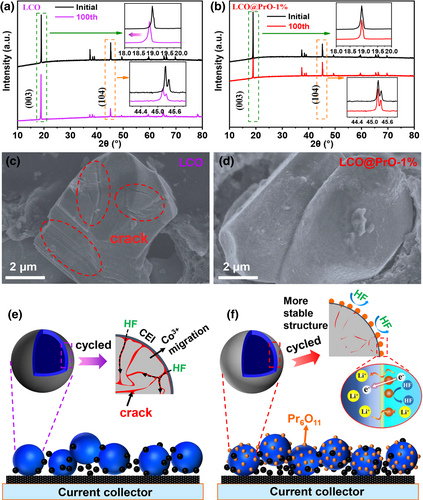
Based on the comprehensive analysis of the LIB performance, EIS test, GITT analysis, KPFM/SEM observation, and XPS etching study, the schematic diagram of structural evolution of active material during charge/discharge is illustrated in Figure 6e,f, and the related mechanism is described as follows. As compared in Figure 6b, due to the structural phase change and the drastic change in lattice parameters, the obvious cracks appear in LCO cathode during the long-term cycling process, which reduce the thermal stability, structural stability, and cyclic stability, and simultaneously form excessive CEI film. Therefore, the modified Pr6O11 with excellent conductivity and good interface compatibility on the surface of LCO can effectively alleviate the erosion by HF originated from the decomposition of electrolyte especially at high-voltage and elevated temperature, accelerate the transfer rate of lithium ions, and form a stable CEI film, thus improving the structural stability and cycling stability of the LCO material.
2.4 Practical Application and Evaluation for Pouch Full Cells
Considering the large-scale fabrication for H-LCO material is of great significance for its practical application in the industry, H-LCO material achieved with 100-gram batch preparation in our work was used to assemble 203450-prototype full pouch cells, which pouch cells were manufactured with graphite as anode and tested according to commercial full battery standard. The detailed composition structure can be seen in Figure S23, Supporting Information. Herein, as displayed in Table S7, Supporting Information, the LCO||graphite and LCO@PrO-1%||graphite pouch cells are designed with a capacity of 450 mAh and with its areal capacity of 5.4 mAh cm−2 for cathodes. Furthermore, it can be obtained from Figure S24, Supporting Information that the charge/discharge curves of pouch cells tested under 0.2 C and between 3.0 and 4.45 V delivered similar discharge capacity with 452 and 448 mAh for LCO||graphite and LCO@PrO-1%||graphite, respectively. The cycling stability of these two pouch cells was tested under 1 C (~450 mA) current density and room temperature. As displayed in Figure 7a, the reversible capacity of pouch cell with bare LCO electrode declined rapidly and fully lost the ability to charge/discharge after ~140 cycles, while the capacity retention rate of pouch cell with modified LCO still remains a large value of 80.3% corresponding to final capacity of ~360 mAh after 200 cycles. Furthermore, as demonstrated in Figure 7b, the rate performance of the pouch cell with modified LCO can deliver more stable trends than the pouch cell without modification at varied current densities from 0.5 to 5.0 C, respectively. Thus, the pouch cells with modified LCO exhibit optimized LIB performance including cycling stability and rate performance, indicating that the Pr6O11 modification can greatly improve the Li+ diffusion kinetics at high current densities and dramatically prolong service lifespan.
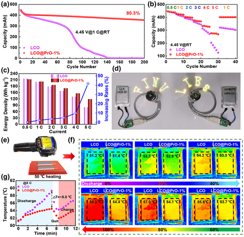
Furthermore, based on the data of the rate discharging capacity, total quality of each pouch cell, and average voltage, the practical energy densities of cells were calculated and compared in Figure 7c, which detailed calculations can be seen in Table S8, Supporting Information. The discharging curves at varied rates are shown in Figure S25, Supporting Information. According to Figure 7c, the change in energy density with the increased rates can be obtained, delivering that the energy density for the pouch cell with Pr6O11 modification can be boosted even by ~42% at 5.0 C rate, which is a great benefit for the cells used in high power output conditions we can imagine. Significantly, the above results do not emphasize that Pr6O11 modification can boost their energy density, but refer to the enhanced performance difference between the cells with or without modification under the same operating conditions. Compared with the selling price for the commercial pouch cell, the cost of modified Pr6O11 in LCO@PrO-1%||graphite pouch cell is very low. Usually, if the energy density for pouch cell increases by more than 10%, the selling price will almost increase by 5–10%, thus indicating that a few extra cost input at Pr6O11 can make more than several times profit. Herein, the discussion for the profit from adding Pr6O11 has been shown in supporting information. As a practical application case shown in Figure 7d, the assembled pouch cells are used to drive the LED (light-emitting diode) fan (also see the working Video S1, Supporting information), thus proving the stability of the power output.
Significantly, the thermal safety of pouch cells plays a critical role in the practical application, and the heat generation of the battery mainly comes from the ohmic heat, polarization heat, and electrochemical reaction heat of the internal electrode.[46] Herein, polarization heat in the charge/discharge may play a dominant role, especially in high-temperature environment and high rate charge/discharge conditions. Moreover, it is widely known that elevated temperature will undoubtedly cause the persistent growth of CEI and increased resistance of active material, leading to the dissolution of transition metal Co and reversible capacity loss, further triggering side reactions and the final thermal runaway.[24, 47, 48] Thus, the related thermal safe property of the obtained pouch full cells with/without Pr6O11 modification was investigated and compared in Figure S26, Supporting Information and Figure 7e–g. As shown in the Figure S26a, Supporting Information for the cells tested under the room temperature of 25 °C, the infrared thermal imaging technology was used to record the surface average temperature (SAT) distributions of the assembled cells at high rate of 5.0 C discharging with different depth of discharge (DOD). Figure S26a, Supporting Information shows that the SAT for the two kinds of cells at 5.0 C are all uniform, also revealing the stable cell assembly. Notably, compared with Figure S26b, Supporting Information, the SAT values of cells keep at ~25.0 °C at the DOD-0% and gradually increase with the DOD depth. At the DOD-100% state, the values for the SAT of LCO||graphite and LCO@PrO-1%||graphite pouch cells are 38.1 and 35.8 °C, delivering a relatively low SAT difference of 2.3 °C. More importantly, lithium ion power batteries are often used under more severe conditions, such as high-temperature and continuous climbing conditions for electric vehicles. Thus, the SAT distributions of the cells at high rate of 5.0 and 8.0 C with different DOD states have been tested and compared in Figure 7e,f. As shown in Figure 7e,f, the SAT values of these two pouch cells were ~50.0 °C before discharging, and elevated with increasing DOD states. From Figure 7g for the DOD-100% state, the SAT value of LCO||graphite pouch cell reached 59.3 °C, while the LCO@PrO-1%||graphite was only 54.4 °C at final discharging state. The delivering SAT difference of ~5.0 °C between these two cells can be obtained, being larger than at room temperature and relatively low rate of 5.0 C. By the way, the real temperature difference inside the battery is usually larger than the SAT values, which tested results can deliver improvement significance for the practical application of modified LCO@PrO-1%||graphite pouch cells. Thus, Pr6O11 modification with improved high-thermal conductivity and stable interface compatibility can directly boost the battery inside heat generation/dissipation, resulting in the enhancement of lithium ion diffusion kinetics and LIB performance especially at high rates and elevated temperatures. The obtained conclusions also strongly support the above results in Figures 2 and 7a,b. This work provides a promising and cost-effective path for the high-energy density LIB manufacturing, being of great significance to the commercial promotion of H-LCO.
3 Conclusions
In summary, a simple 100 g-grade produced approach has been proposed for preparing high-voltage LiCoO2 in this work. For the first time, negative temperature coefficient thermosensitive Pr6O11 are uniformly modified on commercial LCO to prepare LCO@PrO via a liquid-phase mixing combined with annealing method. The modified LCO@PrO electrodes deliver excellent 4.5 V high-voltage cycling LIB performance at 25 and 60 °C, both much better than bare LCO electrodes. Moreover, the assembled 450 mAh LCO@PrO‖graphite pouch cells deliver excellent LIB performance and thermal safety characteristics, which energy density increased even by ~42% at 5 C compared with LCO‖graphite pouch cells, showing excellent commercial application potential. The performance enhancement mechanism induced by Pr6O11 modification was also clearly unveiled, that is, Pr6O11 modification can improve interface compatibility, exhibit improved conductivity at elevated temperature, thus enhance the Li+ diffusion kinetics, and suppress the phase transformation of LCO and its resulting mechanical stresses. In brief, this work demonstrates an effective surface modification strategy to mass-produce excellent performance high-voltage LiCoO2 and offers important new insights and valuable electrode design concepts, being essential for the industrialization of high-energy lithium batteries.
4 Experimental Section
Materials Synthesis
In this experiment, the LCO pristine materials were purchased from Hunan Shanshan Advanced Energy Co., Ltd., and the detailed specification parameters were shown in Table S1, Supporting Information, and Pr(NO3)3·6H2O was purchased from Shanghai Macklin Biochemical Co., Ltd., both of LCO and Pr(NO3)3·6H2O were used directly without any further treatment. LCO coated with Pr6O11 was successfully synthesized by a simple liquid-phase stirring combined with annealing treatment. In typical progress, 100 g LCO and Pr(NO3)3·6H2O were dispersed into 50 and 10 ml deionized water under vigorous stirring at room temperature, respectively. Subsequently, the Pr(NO3)3·6H2O solution was added to the LCO solution according to the different modified proportions, and NH3·H2O was injected slowly into the mixed solution until PH = 11.0 and then stirred for 2 h. The sedimentated product was centrifuged and washed with deionized water, and dried at 80 °C for 6 h. Finally, the dried products were calcined in air at 600 °C for 5 h to obtain target samples. In this report, the modified proportion of Pr6O11 was 1%, 3%, and 5%, which was marked as LCO@PrO-1%, LCO@PrO-3%, and LCO@PrO-5%, respectively.
Materials Characterization
X-ray diffraction (XRD) patterns for the crystalline structure of the samples were examined by Rigaku Ultima employing Cu Kα radiation source (λ = 1.5481 Å). Scanning electron microscopy (SEM, HITACHI, and SU-8010) with EDS mapping and transmission electron microscopy (TEM and JEOL JEM-2100) were employed to observe the morphologies, surface structures, and characteristics of the final products. X-ray photoelectron spectroscopy (XPS, Thermo Scientific ESCALAB 250Xi) was carried out to analyze the chemical state of the obtained samples. The Kelvin probe atomic force microscopy (KPFM, Bruker dimension ICON, Germany) was employed to determine the surface potentials of samples. The ICP-OES (ICP-MS: Agilent 7800) was used to test the mass ratio of samples. The electrical model of Cryogen-free Physical Property Measurement System (PPMS) was utilized to record the resistance of samples from 0 to 70 °C.
Coin-Type Cells Assembly and Electrochemical Measurements
CR2025-type coin cells were assembled to test electrochemical performances. Firstly, the cathodic electrodes were fabricated by mixing the active materials (i.e., bare LCO, LCO@PrO-1%, LCO@PrO-3%, and LCO@PrO-5%), super-P, and polyvinylidene fluoride (PVDF) with a weight ratio of 8:1:1 and then, the above materials were mixed homogeneously with N-methyl pyrrolidone (NMP) as the solvent to form a homogeneous slurry, which was pasted on Al foil and dried at 120 °C in a vacuum oven for 6 h. The punched electrode with loading mass of 3.0 mg cm−2 was matched with the lithium foil counter electrode to assemble coin-type cell in argon-filled glovebox, which electrodes in cell were separated by microporous polypropylene membrane (Celgard 2400) and saturated by electrolyte containing 1 M LiPF6 in ethylene carbonate, ethyl methyl carbonate, and dimethyl carbonate (1:1:1 in volume). Galvanostatic charge/discharge was tested using the LAND CT2001 instrument (Wuhan LAND Electronics. Ltd., China) at varied current densities. Herein, the cycling detailed parameters of coin cells are shown in Table S2, Supporting Information. CHI760E electrochemical workstation was employed to investigate Cyclic voltammetry (CV) and electrochemical impedance spectroscopy (EIS) with the frequency range of 100 kHz–100 mHz at an AC voltage of 1 mV referring to open circuit potential.
Pouch Full Cells Assembly and Electrochemical Measurements
Pouch full cells of LCO||graphite and LCO@PrO-1%||graphite were fabricated as follows. Firstly, the different harvested cathode material was mixed with super-P and binder of PVDF with the weight ratio of 96:2:2 in the agitation chamber to form a homogeneous slurry, using NMP as the solvent. Then, the viscous slurry was coated on both sides on Al foil under automatic drying process, and the obtained cathodic electrode was loaded with 30 mg cm−2 dried slurry. In addition, the anodic electrode with 14 mg cm−2 loading was prepared as similar progress, which contains graphite (95.7 wt.% active material), super-P (1.0 wt.% conductive agent), carboxymethyl cellulose sodium (1.5 wt.% binder agent), styrene-butadiene rubber (1.8 wt.% anti-settling agent), and deionized H2O. Herein, the solid contents of cathodic and anodic slurry were carried out at 62% and 45%, respectively. Subsequently, according to the prepared processes of pouch full cell including electrode cutting, electrode rolling, electrode stacking, cell sealing, electrolyte injecting, cell formation etc., the pouch cells designed capacity with 450 mAh was successfully assembled. Figure S1, Supporting Information displays the pictures of modified LCO material, cut electrodes, and pouch cells. More experiment details for pouch full cell can be obtained from our previous work.[47, 49, 50] Finally, the cycling and rate performances in a voltage range of 3.0–4.45 V were carried out using Neware test equipment, and the infrared thermal imaging technology of Testo Instrument Company (Testo 875-2I) is leveraged to monitor the temperature of the battery surface with temperature range of −30 to 300 °C. Herein, the cycling detailed parameters of full pouch cells are shown in Table S3, Supporting Information.
Acknowledgements
This work was jointly supported by the Natural Science Foundations of China (Nos. 22179020, 12174057), Fujian Natural Science Foundation for Distinguished Young Scholars (Grant No. 2020J06042), Foreign science and technology cooperation project of Fuzhou Science and Technology Bureau (No. 2021-Y-086), Natural Science Foundation of Fujian Province (Grant No. 2018J01660), and Cultivation plan of outstanding young scientific research talents of Fujian Education Department (Grant No. J1-1323).
Conflict of Interest
The authors declare no conflict of interest.


