A single platform image cytometer for resource-poor settings to monitor disease progression in HIV infection
Abstract
Background
For resource-poor countries, affordable methods are required for enumeration of CD4+ T lymphocytes of HIV-positive patients. For infants, additional determination of CD4/CD8 ratio is needed.
Methods
We determine the CD4+ and CD8+ T lymphocytes as the CD3+CD4+ and CD3+CD8+ population of blood cells. Target cells are CD3-immunomagnetically separated from the whole blood, and CD4-Phycoerythrin and CD8-PerCP immunofluorescently labeled. A point-of-care single platform image cytometer was developed to enumerate the target CD3+CD4+ and CD3+CD8+ populations. It has light-emitting diodes illumination, is fully computer-controlled, operates from a 12 V battery, and was designed to be cheap and easy-to-handle. Target cells are imaged on a CCD camera and enumerated by an image analysis algorithm. The cytometer outputs the absolute number of CD4+ and CD8+ T lymphocytes/μl and CD4/CD8 ratio.
Results
The quality of the cell images obtained with the cytometer is sufficient for a reliable enumeration of target cells. The image cytometer achieves an accuracy of better than 10% in the range of 50–1700 cells/μl. Analysis of blood samples from HIV patients yields a good agreement with the TruCount method for CD4 and CD8 count and CD4/CD8 ratio.
Conclusions
The image cytometer is affordable (component costs $3,000), compact (25 × 25 × 20 cm3), and uses disposable test materials, making it a good candidate to monitor progression of immunodeficiency disease in resource-poor settings. © 2007 International Society for Analytical Cytology.
According to the World Health Organization (1), the requirement for HIV monitoring in adults in resource-poor countries is CD4+ T lymphocyte enumeration. For infants, additional determination of CD4/CD8 ratio is required (2). Efforts have been made to develop dedicated flow cytometry (FCM) methods (3-7). These alternative methods are not widespread yet; one of the reasons may be that they still require trained personnel. FCM is therefore limited to use in larger regional facilities and leaves smaller medical centers dependent on time-consuming transport of blood samples to such a facility.
To change this situation, an easy-to-use and affordable, yet reliable, diagnostic tool for enumeration of CD4+ and CD8+ T lymphocytes in smaller hospitals or point-of-care centers is needed. The instrument should be compact, fast, and simple, allowing operation by a low-level skilled user. Several methods are being considered as alternatives for less-expensive CD4 and CD8 enumeration (8-11).
In this paper, we present the development of an affordable point-of-care single platform image cytometer (SP ICM) that can enumerate CD4+ and CD8+ T lymphocytes in whole blood. The instrument is an automated fluorescence microscope that selects the target T lymphocytes based on a two-step procedure: CD3-immunomagnetic separation of CD3+ lymphocytes followed by CD4-Phycoerythrin and CD8-PerCP immunofluorescent labeling, and optical detection of selected CD3+CD4+ and CD3+CD8+ cells. This identification scheme guarantees that only the required CD4+ and CD8+ T lymphocytes are counted and not CD4+ monocytes. The image cytometer is portable (battery-powered) and equipped with a long-lasting light-emitting diode (LED) illumination system, and the test is performed in a disposable chamber. Here, we give the technical details of the cytometer and show that it gives results comparable to a single platform flow cytometer (SP FCM) method. In a different paper, we specify the results from more extensive testing on HIV-positive patients (12).
MATERIALS AND METHODS
Sample Preparation for Image- and FCM
Blood from random-selected HIV-negative patients was collected in K3EDTA vacutainer blood collection tubes and processed within 10 h after draw. Fresh blood specimens were supplied from the MST Hospital, Enschede, The Netherlands. Note that patients not diagnosed with HIV are defined as HIV-negative patients.
For image cytometry, 100 μl EDTA anti-coagulated whole blood was mixed with 10 μl of CD3 EasySep (ES) Ab cocktail (StemCell Technologies, Vancouver, BC) and 10 μl CD4 R-Phycoerythrin (PE). After 15-min incubation at room temperature, 5 μl ES magnetic nanoparticle solution was added and mixed. After 10-min incubation at room temperature, the sample was diluted with system buffer (Immunicon, Huntingdon Valley, PA) to a final volume of 410 μl and mixed. About 320 μl of the sample solution was transferred into an analysis chamber (Immunicon) with inner dimensions of 30 × 2.7 × 4 mm3. Separate titration experiments were performed to determine the optimal concentration of both immunomagnetic and fluorescent labels, the incubation time, and the magnetic separation time (12). For CD4 and CD8 tests, we used 3 μl of CD3 Ferrofluid (Immunicon) for magnetic separation, and 5 μl CD4 PE and 2 μl CD8 PerCP (BD Biosciences, San Jose, CA) for fluorescent detection.
For FCM (TruCount method, BD), blood samples were processed using a lyse-no-wash method according to recommendation of the manufacturer (BD) (13) and analyzed on a FACSCalibur flow cytometer (BD).
CD4 and CD8 T Lymphocyte Enumeration Method
After incubation with CD3-magnetic particles and labeling with CD4-PE and CD8-PerCP, the blood sample is injected into a sample chamber that is placed in the field of a magnetic yoke (14, 15). Here, the CD3+ T lymphocytes, being CD4+ and CD8+ T lymphocytes, are extracted from the sample and pulled up toward the analysis surface (glass) of the sample chamber while other cells move to the bottom of the sample chamber under the influence of gravity, as shown schematically in Figure 1. Fluorescence emitted from a well-known area of the analysis surface is sequentially imaged for each fluorophore, and the number of CD4+ and CD8+ T lymphocytes in the area is determined by image analysis. Magnetically separated cells derive from a precisely known volume of the chamber. Consequently, the absolute number of CD4+ and CD8+ T cells per unit volume, and therefore CD4/CD8 ratio are determined. Although CD4+ T lymphocytes stain brighter with CD4 than do monocytes, the presence of dim CD4+ T lymphocytes makes identification of monocytes by adjusting the fluorescence detection levels of the image cytometer more difficult. We used PE and PerCP as fluorescent labels, because these two fluorophores can be excited by the same light source, (see Imaging Optics section), and there is a minimal overlap between their emission spectra, minimizing the cross-talk that may occur between them.
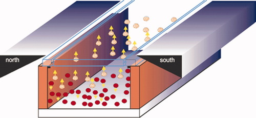
Schematic representation of the immunomagnetic separation principle: immunomagnetically labeled cells (yellow balls) move to the upper surface of the chamber, while other cells (red balls) move to the bottom under influence of the gravity force.
RESULTS
The configuration of the image cytometer (Fig. 2) and the different components that are used for building the instrument were chosen such that the demands on quality of acquired cell images, power consumption, compactness, and affordability are optimally satisfied.
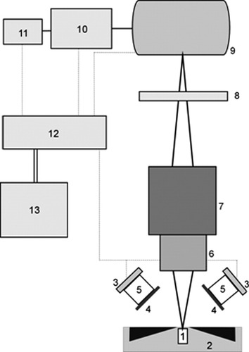
Functional design of the stand-alone image cytometer. An image of labeled T lymphocytes, which have been magnetically collected at the surface of the sample chamber [1] inserted into the magnetic yoke [2], is taken. LEDs [3] illuminate the sample, and excitation filters [4] suppress LED-emitted light in the spectral region that overlaps with the fluorescent signal. An emission filter [8] selects the fluorescent signal. Custom optics [5] collimates the LED output on the analysis area of the sample chamber. A standard microscope objective [6] images the lymphocyte fluorescence onto a CCD camera [9]. The objective is mounted on a stage [7] to adjust the focus. Acquired images are transferred to a single board computer (SBC) [10] that is operated via a touchscreen monitor [11]. These images are analyzed in the SBC using a dedicated image analysis algorithm, from which the number of T lymphocytes per unit volume is determined. The CCD camera, LED units, the SBC, and the touchscreen are connected to a 12 V rechargeable battery [13] via a custom-built electrical circuit [12]. All components are enclosed in a mechanical frame (not shown), with a separate frame for the batteries.
Illumination Configuration
The cytometer should give a high signal-to-noise ratio (SNR) for images of separate cells, so that they can reliably be counted. This means that the intensity of illumination should be both high and homogeneous over the analysis surface. A nonhomogeneous illumination would cause a nonuniform fluorescent signal and a nonuniform background, leading to problems in the image analysis. The illumination scheme implemented in our cytometer consists of four 5 W, 470 nm, Luxeon V Star LEDs (LXHL-LE5C, Lumileds, San Jose, CA) mounted symmetrically on top of the magnetic yoke. Each LED unit requires a typical operating voltage of 6.84 V at 700 mA and outputs a luminous flux of 48 lm (Lambertian radiation pattern).
We used a fiber coupling lens with a focal distance of 16 mm (Roithner Lasertechniek, Vienna, Austria) to collimate the output of each LED onto the upper surface of the sample chamber. A lens holder for Luxeon LEDs (Fraen Corporation, Reading, MA) assembles LED and lens, and this assures proper relative positioning of these components. A 470AF50 excitation filter (Omega Optical, Brattleboro, VT) was positioned in front of the lens to reduce the LED output overlapping with the fluorescence of PE, hence, contributing on reduction of the background. This filter blocks to optical density >4.0 for the wavelength range 350–440 nm and 500–800 nm, as measured with a spectrophotometer (Shimadzu UV-2401PC, Shimadzu, Kyoto, Japan). All these optical components were aligned and packed together using 25-mm shrink tubing (Farnell In One, Leeds, UK). A schematic representation of an assembled LED module is shown in Figure 3. The four legs of each module are heat-staked onto a metallic plate, which serves also as heat sink. In this way, an excellent optical assembly with high mechanical stability is obtained. The four LED modules are positioned such that the optical axis makes an angle of 45° with the plane of the stage. Given the illumination geometry and the magnetic yoke configuration, the 45° was optimal to obtain a maximum light intensity with relatively good uniformity at the top of the sample chamber. The distance between each LED module and the top of the chamber can be properly adjusted. The optimum distance was found to be ∼20 mm. For this distance, each LED module delivers ∼40 mW/cm2 at the top of the chamber, as measured with an optical power meter (model 840, Newport Spectra-Physics BV, Utrecht, The Netherlands). The overall light intensity distribution on the measuring area, where beams of four LED units overlap, has a coefficient of variation (CV) of <10% as determined with the WinCamD beam diagnostics (Gentec-EO, Québec, QC).
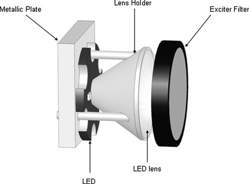
Schematic of the LED module implemented in the image cytometer.
Imaging Optics
The number of pixels used to image one cell is an important parameter in the design of the instrument. To obtain good discrimination of hot pixels, the number of pixels per cell should be maximized. This will lead to a decrease in the SNR when the light intensity per pixel is compared versus the noise in surrounding pixels. In addition, the accuracy is increased because the resolution increases, and it will become easier to separate two neighboring cells. On the other hand, the larger the amount of pixels used per cell, the fewer cells can be imaged on the CCD surface, which will lead to poor sampling statistics. Therefore, the number of pixels per cell was optimized to obtain the largest SNR with a minimum number of pixels per cell.
Fluorescently labeled cells, lying at the upper surface inside the chamber, are imaged onto the CCD camera using a 10× microscope objective (NA 0.2) (Lomo Optics, Germantown, MD) mounted on a stage that enables adjustment of the focus. A sample chamber with fluorescent beads is used to determine the focus upon which the adjustment is locked. In the cytometer, we use the objective to realize a magnification of 6.3×. The CCD covers a field of view (FOV) of 1.09 × 0.73 mm2 of the upper surface. Fluorescently labeled CD4+ T lymphocytes are randomly located on the object plane and imaged as spots of ∼25 pixels, which was found as a reasonable compromise between SNR and statistical variation. The lymphocytes within one FOV come from a volume of 0.80 μl of the labeled blood sample (FOV multiplied by the depth of the chamber). For each sample, cell counts were performed for three FOV areas and the counts were averaged. For blood with a CD4+ T lymphocyte count of 50/μl, this procedure should yield a statistical (Poisson) variation of <10% of the count.
Factors contributing to the background signal are autofluorescence from the labeled and nonlabeled cells at the upper surface of the chamber and from the serum with the red blood cells in the sample chamber, as well as reflected and stray LED light and room light. Use of a proper emission filter will suppress part of these factors and minimize average background signal. In our image cytometer, the PE fluorescence, emitted by labeled CD4 cells, was filtered by a 595AF60 emission filter (Omega Optical). This filter is blocked to optical density >4.0 for the wavelength range of 400–550 nm and 670–800 nm, being sufficient for achievement of a high SNR (see Instrument Characterization section). For PerCP, a 695AF55 emission filter (Omega Optical), having similar performance as the 595AF60, was used. A filter changer was mounted to switch between these two filters, enabling capturing of PE and PerCP signals.
The emission spectrum of a 470 nm LED, as measured with a monochromator (HR460; Jobin-Yvon, Paris, France), containing a blazed holographic grating with 1,200 grooves/ml, is presented in Figure 4, together with the characteristics of the excitation and emission filters, and the absorption and emission spectra of PE. The spectrum of the LED matches well with the absorption spectrum of PE. A higher yield could be achieved by using a LED with an output wavelength of 505 or 530 nm, also available from Lumileds. Then, however, a larger interference of the LED light with the emission of PE occurs, because the emission spectrum of these LEDs is broad (spectral width at half maximum intensity 30 nm). This results in a higher background in the images. As will be shown in Instrument Characterization section, the choice of the excitation wavelength is conditioned by the SNR of cell images.
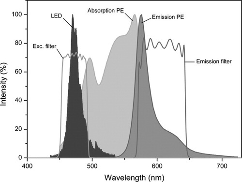
Emission spectrum of the 470 nm LED, absorption and emission spectra of PE, and transmission spectra of the 475AF50 excitation filter, and the 595AF60 emission filter implemented in our image cytometer. [Color figure can be viewed in the online issue, which is available at www.interscience.wiley.com.]
CCD Camera
The noise present in lymphocyte images arises from photon shot noise of the emitted (auto)fluorescent light and stray light that passes through emission filter, and from noise generated by the CCD camera (dark current noise, readout noise, and thermal noise). An additional contribution to the noise stems from the variance in sensitivity of separate pixels of the CCD chip. Therefore, it is important to use a CCD camera with low noise characteristics and minimal sensitivity variation. The CCD camera used (ST-402ME; SBIG, Santa Barbara, CA) was designed for astronomical purposes, where faint details of dim astronomical objects have to be determined. In analogy, we have to image the weak immunofluorescence of labeled cells. This camera is offering a high performance at relatively low costs. The imaging CCD chip (Kodak KAF-0402ME imaging CCD; Kodak, NY) has 765 × 510 pixels (9 μm × 9 μm), and combines a large well capacity (∼100,000 e−) with a low dark current (1 e−/pixel/s at 0°C) and a low readout noise (17 e− RMS). The camera has a 16 bits A/D converter. Owing to the implementation of a microlens array over the pixels, it has a high quantum efficiency (∼75% at the peak of PE emission). Dark image subtraction can be performed for images acquired with exposure times longer than 1 s. The camera can operate from a 12 V battery or other unregulated 12VDC source.
Single Board Computer and Touchscreen
For data collection and analysis, we use a single board computer (SBC). Compared to a normal computer or a laptop, the SBC is an inexpensive solution that can easily perform overall cytometer control. Furthermore, its size, weight, and power requirements allow development of stand-alone platforms. The cell images are downloaded from the CCD camera to the SBC. This is a Micro PC with a VIA Eden™ ESP6000 667 MHz processor (EES-3610, Evalue Technology, Taiwan); a 256 MB SDRAM SODIMM memory (SimpleTech, USA) and a 2.5″ hard disk (Toshiba, Japan). The Micro PC is a low-power fanless embedded system (operating with 5 V-DC at 5 A) with dimensions of 220 mm × 65 mm × 147 mm and weighs 1.7 kg. An 8.4″ LCD-TFT touchscreen monitor (B084SN03 V2, AU Optronics, Taiwan) with a JTHC084DRA1 touchscreen controller (AU Optronics) is connected to the SBC. The touchscreen is powered by a 12 V external voltage.
Housing and Power Supply
The total power required for cytometer operation is 55 W, from which about 50% is used by SBC and touchscreen. To minimize power consumption, the LEDs are controlled via a USBREL8LC relay card (Quancom, Germany) and operate only during the image acquisition.
The cytometer needs 5 V for the SBC, 6.8 V for the LED units, and 12 V for the CCD camera and LCD-TFT touchscreen. A home-built power unit contains one Yuasa NP 7-12 12 V rechargeable battery with a capacity of 7 Ah (Yuasa, Japan), that is charged by a LM12010-3T 12V 1A battery charger (MEC, Hong Kong). Two LT1083 voltage regulators (Linear Technology, USA) with an output 5 V and 6.8 V are used. The power supply is connected via a five-pole connector to the cytometer. In spite of the small battery, the current prototype runs for about 2.5 h, without the need for recharging the battery. In this time, 100 cell counts can be determined. An external car battery can be connected to the power unit to operate in case of power loss. A 30-Ah battery would then last for about 10 h operation.
A home-built preliminary aluminum housing of 25 cm × 25 cm × 20 cm accommodates all components of the cytometer, except for the power unit. The optical parts, including CCD and magnetic yoke, are positioned at the front part of the instrument. A schematic layout of this section is shown in Figure 5A. The user inserts a sample chamber from the front into the magnetic yoke. The SBC is mounted on the rear vertical plate, which serves as heat sink. The power unit, built in a separate housing, is mounted on the outside of the rear plate. The touch screen is positioned on top of the cytometer at an angle of 45°. A photograph of the cytometer is shown in Figure 5B. Total weight is 15 kg; instrument without power unit weighs 10 kg.
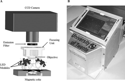
(A) A schematic layout of the optical part of the image cytometer. See text for more details. (B) A photograph of the instrument prototype.
Image Analysis
To obtain the number of CD4+ and CD8+ T lymphocytes per unit volume, we analyze the fluorescence images using a dedicated algorithm written in ImageJ, a public- domain Java image processing software package (NIH, MD) (16). The algorithm consists of the following steps.
Background subtraction: Corrects for nonuniform illumination, variation in the sensitivity of the CCD pixels, and presence of dust in the optical system.
Thresholding: Transforms the grey-scale image to a binary image. Here, all the objects (cells) that have higher intensity than a preset threshold are assigned as 1, and the rest of the objects that have lower intensity (background) are assigned as 0.
Watershedding: Separates cells that are close together (17). The watershedding transformation works by replacing all foreground (cell) pixels with a grey value that is proportional to their distance from the nearest background pixel. This is the so-called Euclidian distance map. From this, the centers of the cells are calculated by finding the ultimate eroded points, i.e. the points that are equidistant from the cell edges. These points are then dilated until they meet another dilated object, and there a segmentation line is drawn.
Counting: Enumerates all objects assigned as 1 (cell).
Separation: An additional step that first estimates the average area of a cell in the image and then divides the total area of overlapping cells by this average. This step is necessary for images with a high cell count to allow a better separation between overlapping cells.
All steps of the algorithm are implemented in a macro that enables an automated image analysis. Analysis of one image takes less than 10 s in the SBC. To determine the quality of the overall procedure of acquisition of an image and its analysis, we follow Young et al. (18) and define a quality index (QI) of an image with cells as QI = (〈Icell〉 − 〈Ibackg〉)/〈σnoise〉, where 〈Icell〉 and 〈Ibackg〉 are the average fluorescence intensity of the lymphocytes and the background from several representative areas in the image, and 〈σnoise〉 is the average standard deviation of the total noise present in the image. Note that the maximum lymphocyte intensity for each area is taken as 〈Icell〉. Using this definition, the QI can serve to determine how well an image was analyzed. We use the term QI instead of SNR as it also contains the accuracy due to the image analysis algorithm. A selection of the cells counted in the original image, serving as a qualitative assessment of the counting procedure applied, is provided from the algorithm.
In Figure 6, we illustrate the image analysis. It shows a typical image of CD4 T lymphocytes, magnetically selected using CD3-ES, and fluorescently labeled with CD4-PE. The results of background correction, thresholding, and watershedding are also presented. In this case, apparently, all cells have been identified by the image analysis procedure. Note that this image corresponds to a blood sample having around 1,500 T-lymphocytes/μl, illustrating that the algorithm works well, even for high CD4 counts. However, in general, we estimate that counts can reliably be made in the region of <1,500 cells/μl, and above this concentration deviations may occur (see also Evaluation of the CD4 and CD8 T-Cell Enumeration section).
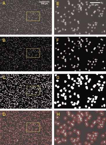
(A) Typical image of CD3-ES/CD4-PE immunolabeled CD4 T cells obtained with Configuration 5 of the instrument prototype; this image after applying a background correction (B) and thresholding (C). (D) A merge of the original image with, in a red circle, the cells that have been selected as positive by the image analysis algorithm (watershedding). (E–H) Enlarged images from the selected area as shown in A–D, respectively.
Software Shell
A software shell (LabView, National Instruments, Austin, TX) that integrates all hardware and software into a functional and simple user interface was developed. The measurement procedure is started by inputting the patient info and the sample number. Next, the exposure time needed for acquiring a sample image is set. After a dark image and sample images for PE and PerCP have been captured, the dark image is subtracted from the sample images. Finally, the image analysis takes place, and a report that contains the patient info, the CD4 count and CD4/CD8 ratio, and the images of the blood sample is presented. The whole procedure from image capture to the cell count result takes less than 2 min.
Instrument Characterization
During the development of the image cytometer, we built and tested several configurations of LED-filter-collimator configurations. The QI of representative cell images, being the guiding criterion for prototype development, was evaluated for each configuration. A summary of five different configurations that were explored is presented in Table 1.
| Instrument configuration | |||||
|---|---|---|---|---|---|
| 1 | 2 | 3 | 4 | 5 | |
| Components | |||||
| LED units | 2 Luxeon Star/Oa | 2 Luxeon Star/Oa | 4 Luxeon V Star | 4 Luxeon V Star | 4 Luxeon V Star |
| LED optics | Star/Ob | Fiber coup. lens | Fiber coup. lens | Fiber coup. lens | Fiber coup. Lens |
| Exciter filter | None | None | None | 470AF50 | 470AF50 |
| Emission filter | 575DF25c | 575DF25c | 575DF25c | 575DF25c | 595AF60 |
| QI | 23 | 26 | 37 | 62 | 69 |
- LEDs (470 nm) were used as excitation sources. Images were acquired with the ST-402ME CCD camera using a ×10 NA0.2 microscope objective. An exposure time of 10 s was used for all configurations. No excitation filters were used for Configurations 1, 2, and 3. Five microliter instead of 10 μl CD4-PE was used in Configurations 4 and 5. Note that use of LEDs with larger wavelengths resulted in a decrease of the QI of cell images for reasons discussed in Imaging Optics section (results not shown).
- a 1 W, 470 nm, Luxeon Star/O LEDs (LXHL-NB98, Lumileds, San Jose, CA).
- b Optics for Star/O Luxeon LEDs (Fraen Corporation, Reading, MA).
- c 575DF25 emission filter (Omega Optical, Brattleboro, VT).
The QI improved from 23 in Configuration 1 with two 1 W 470 nm LEDs, to 69 in Configuration 5 with four 5 W 470 nm LEDs. This is a result of several factors, such as a higher excitation power, better collimating optics, introduction of an exciter filter that reduces LED output overlapping with the PE fluorescence, and use of a more efficient emission filter. In Configuration 5, because of the high QI, the amount of CD4-PE used for immunofluorescent labeling was decreased from 10 to 5 μl. Configuration 5 also gives the best result with respect to background uniformity, with a CV of 5% (along the field profile as shown in Fig. 7) vs. a CV of 41% in Configuration 1. This improvement is due to use of better collimating optics and proper alignment of LED modules. Using this configuration, it was possible to detect the BD QuantiBrite beads, bearing ∼5,956, 26,653 and 69,045 PE molecules, with a QI > 30 (exposure time of 10 s). In this case, extrapolation of the experimental data indicates that it might be possible to discriminate beads bearing a few hundred of PE molecules.
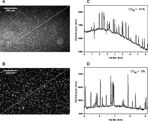
Raw images of CD3-ES/CD4-PE immunolabeled CD4 T cells obtained with Configurations 1 (A) and 5 (B) of the instrument prototype (Table 1) and the respective intensity field profile (C,D) along the diagonal line as indicated in these images. Note the negative peaks in (C) due to the presence of red blood cells. Contrast enhancement was applied to these images for clarity.
Next, the influence of the QI on the accuracy of cell counting was investigated by analyzing images with known number N of CD4+ T lymphocytes. Blood samples with a CD4 count that varies from about 50 to 500 cells/μl were used. We selected this range because it seemed most relevant for AIDS monitoring in resource-poor settings. From each image, several images with QIs varying from about 5 to 40 were generated by adding random noise to the original image. Next, these images were analyzed with the algorithm defined in Image analysis section, and a relative counting error was determined for each image. This error is defined as (|N′ − N|)/N × 100%, where N′ is the number of counted cells. Figure 8 shows that the relative error of cell counting decreases with increasing QI. For QI > 30, the error that results from the simulations is less than 2%. Considering that, in actual measurements, the QI of the cell images we obtain is usually better than 30, we expect that the image analysis inaccuracy is less than 2%. These simulations also illustrate the dynamic range of the image analysis algorithm in the clinically relevant range of 50–500 cells/μl. Calculations were also performed with images of fluorescent beads that have a similar size as T lymphocytes (Fig. 8). These simulations confirm the results achieved with images of CD4+ T lymphocytes.
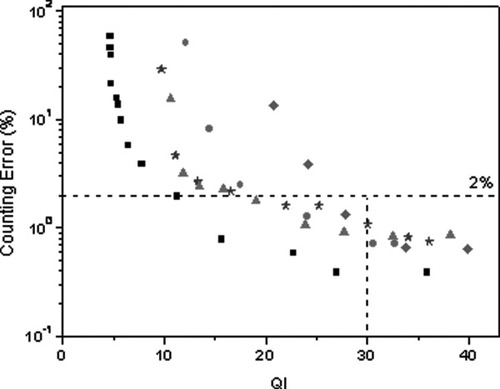
Relative error of cell counting vs. the QI for images with a count of 70 (•), 132 (★), 252 (▴) and 433 (♦) cells/image and an image with fluorescent beads (▪). For QI ≥ 30, the error is <2%.
We compared these results with simulations performed with generated cell images using Matlab software (Mathworks, Natick, MA). These generated images resemble the experimental settings, such as magnification, used for cell imaging and size of the CCD chip. The same image analysis procedure as for the real cell images was applied, and the error was estimated for various number of cells/μl. A good agreement between the results obtained with the generated and real cell images was found, confirming the accuracy achieved with the cytometer. Moreover, analysis of both generated and real cell images indicates that the sum of counting error and statistical (Poisson) variation is less than 10% in the range of 50–1,700 cells/μl.
Evaluation of the CD4 and CD8 T-Cell Enumeration
The performance of our SP ICM was evaluated by measuring samples of HIV-negative patients and comparing the results with the TruCount method. To test CD4 count, samples from 45 patients were analyzed. Parallel blood samples of each patient were processed in both instruments. The correlation coefficient and the regression line for results of our image cytometer and the flow cytometer are shown in Figure 9A (R = 0.98, P < 0.0001; slope 0.97). The correlation coefficient of 0.98 indicates a good agreement. The slope of 0.97 indicates that the deviation from FCM is 3%. The Bland–Altman plot (19) that compares absolute CD4+ T lymphocyte counts of image cytometer and FCM (cell counts varying from 148 to 2,220/μl) is shown in Figure 9B. A bias of −54 cells/μl and 95% limits of agreement of −261 to 153 cells/μl were found. For CD4 counts higher than 1,500 cells/μl, the FCM gives higher values than the image cytometer, and some results fall outside the 95% limits of agreement. This is probably due to the image analysis algorithm that cannot completely separate all overlapping cells in an image at these numbers.
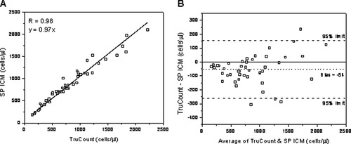
(A) Linear regression plot of CD4 T cell count for 45 HIV-negative patients obtained with the SP ICM and the TruCount method. (B) Bland–Altman plot comparing cell counts obtained with the SP ICM and the TruCount method. There is a bias of −54 cells/μl compared to FCM (dotted line). Dashed lines indicate upper and lower 95% limits of agreement, whereas solid line indicates zero bias.
Next, further tests were performed for determination of CD4 and CD8 count, and CD4/CD8 ratio by analyzing samples from 50 patients. In Figure 10, the regression line and Bland–Altman plot for CD8 count (cell count varying from 18 to 1,242/μl) and CD4/CD8 ratio are shown. A correlation coefficient of 0.96 (P < 0.0001) was found in both cases, and the slope was 0.90 and 1.12 for CD8 count and CD4/CD8 ratio, respectively. For CD4, correlation coefficient was 0.96 (P < 0.0001) and slope 0.98 (graph not shown). Bland–Altman comparison method shows a bias of 33 cells/μl (95% limits of agreement of −106 to 172 cells/ μl) and −0.38 (95% limits of agreement of −1.24 to 0.48) for CD8 count and CD4/CD8 ratio, respectively. This test demonstrates the ability of our instrument to reliably determine both CD4 count and CD4/CD8 ratio, being relevant for staging of HIV infection in infants. In addition, it confirms the good agreement between our instrument and gold standard methods such as FCM in this case. More extensive testing with HIV-negative and -positive patients for CD4 count is reported elsewhere (12).
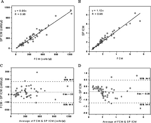
Linear regression and Bland–Altman plots of CD8 T cell count (A and C) and CD4/CD8 ratio (B and D) for 50 HIV-negative patients obtained with the SP ICM and the TruCount method. There is a bias of 33 cells/μl for CD8 count and −0.38 for CD4/CD8 ratio compared to FCM (see dotted lines in C and D). Dashed lines indicate upper and lower 95% limits of agreement.
DISCUSSION AND CONCLUSIONS
We have presented the design, realization, and characterization of an affordable, rugged, and portable SP ICM for point-of-care CD4+ and CD8+ T lymphocyte enumeration. The cytometer reliably enumerates immunofluorescently labeled cells that have first been immunomagnetically selected. This enables enumeration of CD4+ and CD8+ T lymphocytes as CD3+CD4+ and CD3+CD8+ T lymphocytes, thus avoiding counting CD4+ monocytes. A good correlation with results obtained with the TruCount method was shown, especially at concentrations most relevant for HIV patients.
The results were obtained using a simple 4 × 5 W LED illumination system and standard optics in the cytometer. LEDs (3 W), provided with proper optics, may be used as well, reducing the total power required for cytometer operation. Alternatively, fewer LED units could be used. The CCD camera, chosen for its large dynamic range and low noise characteristics, is still a relatively expensive element in the set-up. We anticipate, however, that advances in camera chip technology will yield more affordable cameras, with similar performance as the one currently integrated in the cytometer. The use of a SBC and a touchscreen allows integration of all components in a stand-alone platform that is battery-powered. Further decrease in physical dimensions of the instrument, currently mainly determined by the size of the SBC and the CCD camera, can be obtained by using board versions of both components. A simple algorithm written in ImageJ, running in the SBC, performs the image analysis.
Generally our images have QI values higher than 30, which yields an accuracy of better than 10% for T lymphocyte counts in the range of 50–1,700/μl. This result was confirmed by the simulations we performed by considering experimental conditions. Tests on patients show a good correlation with the TruCount method for both CD4 and CD8 count, including CD4/CD8 ratio. Comparison according to the Bland–Altman method shows a good agreement between the image cytometer and the TruCount method, especially in the relevant range below 500 cells/μl. In view of further characterization of the instrument with respect to high temperature and high humidity conditions, more tests will be performed both under simulated conditions and on HIV patients in Africa.
We conclude that we developed a point-of-care instrument that is suited to accurately perform on-site HIV monitoring. The development is made possible by combining an immunofluorescent detection method with the latest technology available for LED light sources, CCD camera chips, computer boards, and a dedicated digital image analysis algorithm. This is an automated microscope and no flow of the sample is required. After the user inserts the sample chamber into the instrument, the result of analysis is available in less than 2 min. This automated operation makes it easy to handle. The total component costs (single unit of the shelf price) are about $3,000. It is difficult to give an estimate of how much a commercial cytometer will cost when built from these components, as it will be heavily dependent on the number of instruments built.
Future work will be focused on further improvement of the cytometer performance, reduction of instrument costs, and exploring the possibilities for building a multipurpose system based on new advanced technologies. This will be implemented by upgrading several components of the instrument. For example, the height of the current sample chamber might be significantly reduced in combination with a lower magnification than used now (6.3×), which should eliminate the need for blood dilution and could substantially reduce the fluorescent background. Currently, sample handling is done by pipetting and mixing of reagents and blood. An alternative configuration could be a microfluidic cuvette based procedure for sample handling. In this case, the amount of blood sample and the amount of reagents used for sample preparation can be reduced. Consequently, the total costs per test will be substantially reduced, provided the microfluidic system is affordable. Rodriguez et al. (8) realized a microchip-based sample handling module that is read out in a microscope set up. LabNow announced the launch of a portable point-of-care analyzer, including its CD4 BioChip (9). We will work toward a microfluidic sample preparation procedure that allows injection of the blood sample in a mixing chamber that contains all reagents needed in tablet form or in freeze-dried conditions. Finally, we will explore the possibility to use 1:1 imaging (20), which can result in an improvement of the QI of images acquired, and at the same time, a better sampling statistics will be obtained. The feasibility of implementing these components into a microfluidic version of the instrument, including the efficiency and performance, will be investigated.
To conclude, the point-of-care image cytometer presented here is a compact, stand-alone, easy-to-handle, and affordable instrument, which can accurately perform CD4+ and CD8+ T cell enumeration in whole blood, making it a good candidate for staging of HIV in Africa and other resource-poor settings.
Acknowledgements
We gratefully acknowledge fruitful discussions about image analysis with Dr. Y. Garini, B. Vermolen, and Prof. I.T. Young from The Delft University of Technology, Delft, The Netherlands. We thank I. Vermes, M.D., Ph.D. and C.H.H. ten Napel, M.D., Ph.D., from the MST Hospital in Enschede, The Netherlands, for providing samples of HIV-negative patients.


