Efficiency of using adaptive artificial boundary conditions at computer simulation of contrast spatio-temporal laser-induced structures in a semiconductor
Funding information: Russian Science Foundation, 19-11-00113
Abstract
Many problems of modern laser physics are governed by equations or sets of equations in an unbounded domain. For solving these problems using the computer simulation, it is necessary to introduce the bounded domain, which size should be extended significantly to avoid the spurious wave reflection from the domain boundaries. Alternatively, the artificial (non-reflective or transparent) boundary conditions should be stated. This approach is also effective for enhancing computation performance at the numerical solution of the nonlinear partial differential equations (PDEs). In the current paper, we investigate the laser pulse propagation in a semiconductor, governed by the Schrödinger equation, under the appearance of spatio-temporal contrast structures of semiconductor characteristics. Their evolution is described by a set of PDEs. The optical pulse is partly reflected from the boundaries of these structures. Consequently, even a little reflection of the optical pulse from the artificial boundaries can essentially distort the numerical solution. Thus, these artificial boundary conditions must possess a high quality to minimize their reflection coefficients. With this aim, we propose the method for constructing adaptive artificial boundary conditions and discuss their advantages.
1 INTRODUCTION
Many problems of laser physics and nonlinear optics are governed by sets of nonlinear time-dependent PDEs. In particular, the pulse interaction with a semiconductor is governed by such sets of the PDEs. At certain parameters, the interaction can be accompanied by an optical bistability. This phenomenon is a base for the development of all-optical data processing devices and attracts the interest of many authors.1-6 Recently,7 it was shown that the laser beam longitudinal diffraction plays a fundamental role at the laser pulse interaction with a semiconductor under the appearance of the laser-induced high absorption domain because this leads to the reflection of laser energy from the domain boundaries. This phenomenon can essentially change the process of this interaction. To describe the laser pulse reflection from the high absorption domain, it is necessary to involve in the set of equations the nonlinear Schrödinger equation with the second-order derivative on the coordinate along which the optical pulse propagates. As a consequence of this, to increase the computer simulation efficiency, one needs to apply the artificial boundary conditions (ABCs) for the nonlinear Schrödinger equation.
It should be stressed that during the last decades, many authors pay attention to solving the wave equation and the Schrödinger equation in an unbounded domain (see, e.g., References 8-40). Applying computer modeling techniques for such problems requires also introducing artificial boundaries. In turn, this may lead to the occurrence of a spurious wave reflection from the boundaries. To avoid this reflection, one could solve this problem by shifting the artificial boundaries afar the domain in which the computation occurs. Obviously, this way is impractical from a computational point of view and leads to a significant increasing computational expense, which could become a crucial problem in solving multidimensional problems.
Another way to avoid a spurious wave that appeared due to a laser beam reflection from the artificial boundaries is the introducing transparent (non-reflecting) ABCs. Previously, various authors have proposed methods for transparent ABCs constructing. So, for the 1D linear Schrödinger equation, exact transparent ABCs were also developed. However, their implementation requires information about the solution on all previous time layers, which is unacceptable for the numerical solution due to the computational restrictions. Approximate ABCs could be constructed without all that information, but they lead to a reflected wave's appearance. At linear propagation of the laser beam, the presence of a reflected wave, which amplitude is about 3%–5% of the incident wave amplitude, may be acceptable. But at the optical wave propagation in a nonlinear medium described by the corresponding nonlinear Schrödinger equation, a reflected wave with such amplitude leads to significant distortion of the numerical solution. Therefore, the construction of effective ABCs, which could be easily applying in computer modeling, is an urgent problem.
In our opinion, using the information about the solution in the vicinity of the artificial boundary is one of the promising ways for adaptive ABCs construction.25, 36-39 In Reference 38, it was proposed to compute an effective wavenumber using the Fourier-Gabor transform. This approach is also effective for multidimensional problems because it is possible to write a chain of the corresponding 1D problems. However, such an approach has at least two disadvantages. Firstly, it is not always possible to compute analytically the required integral. Secondly, and this seems more important, in the case of the optical radiation nonlinear propagation, the problem exact solution is usually absent. Let us note that in Reference 39 the nonlinear multidimensional problem was reduced to a chain of 1D problems using the splitting method, and, therefore, the constructed finite-difference scheme was non-conservative according to certain invariants of the problem.
In the current paper, we develop the adaptive ABCs based on computing the time-dependent local wavenumber (or local group velocity) of the laser beam (or pulse) near the artificial boundary. An algorithm of local wavenumbers computing is based on the problem invariants parts. At their computation, we pay careful attention to the correctness of the spurious wave accounting. For clarifying the proposed method's efficiency, we compare the computer simulation results obtained by using non-adaptive ABCs or adaptive ones with the corresponding solution of the Schrödinger equation computed in large enough. Their effectiveness is also demonstrated at solving the 2D problem of the laser pulse propagation in a semiconductor. The necessity of introducing the adaptive ABCs for the Schrödinger equation is illustrated by considering the laser beam propagation under its strong diffraction.
The paper is organized as follows. Section 2 is devoted to the statement of the 2D problem of the laser-induced electron-ionized-donor plasma generation in a semiconductor. We discuss a mathematical model for the problem under consideration, including two ways for standing initial problem for the Schrödinger equation. Presented results of the computer modeling demonstrate the fundamental role of the laser beam longitudinal diffraction under investigation. In Section 3, we develop non-adaptive and adaptive ABCs for the 1D Schrödinger equation and propose the numerical method for their computation. On the base of the provided simulations, we proved the efficiency of the second approach. In Section 4, we briefly conclude the main results.
2 THE 2D PROBLEM OF LASER-INDUCED ELECTRON-IONIZED-DONOR PLASMA GENERATION IN A SEMICONDUCTOR
2.1 Mathematical model of 2D problem
First of all, let us stress that both Schrödinger equations with the corresponding choice of their diffraction coefficients and the initial conditions are equivalent. We demonstrate this below.
Above the dimensionless spatial coordinates x, z belongs to the ranges [0,Lx], [, ], respectively. The laser pulse propagates along z-coordinate. The parameter νz characterizes the laser pulse group velocity and denotes the dimensionless velocity of the laser pulse propagation. Coordinate x is perpendicular to z-coordinate, and it is named as transverse coordinate. Dimensionless time is notated by variable t. Lt characterizes a dimensionless time interval during which the laser pulse interaction with a semiconductor is analyzed. The electron diffusion coefficients , , and the diffraction coefficients , and the electron mobility coefficients μx, μz are non-negative parameters. ϵ is a dielectric permittivity of a medium. Parameter γ depends, in particular, on the maximal concentration of free charged particles. Parameter δ0 denotes the laser energy maximal absorption. According to the physical sense of the problem, the concentrations n(x, z, t), N(x, z, t) and the absorption coefficient δ(n, N) must be non-negative. Because of the chosen normalization of the parameters, the ionized donor concentration N(x, z, t) must not exceed unity.
However, for unbounded domain on a spatial coordinate, as a rule, it supposes that the function A and its n-th derivatives decrease exponentially at tending of the corresponding coordinate to plus or minus infinity.
It should be stressed that the size of the spatial domain in z-direction is determined by the requirement of optical pulse non-reflection from the domain boundaries at providing computations. Depending on different characteristics of the laser pulse interaction with a semiconductor, the values are chosen, and they could be rather big and have to be increased with growing of time interval. Obviously, using this extended domain increases essentially the computational cost of the problem solving.
Choosing parameter β as follows: β = 2πχ and taking into account the expression (13), we see that Equation (14) coincides with Equation (4″) except the last term corresponding to a homogeneous shift of the beam phase with time. But this shift does not influence both the laser beam profile and shape and the pulse interaction with a semiconductor. Nevertheless, using these equations ((4′) and (4″)) at computer simulation may lead to different requirement on a choice of the difference grid steps.
2.2 Computer modeling of the 2D problem
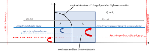
In Reference 7, we demonstrated that the optical pulse reflects partly from the boundaries of the contrast structures of the high electron concentration induced in a semiconductor by laser radiation. This occurs due to the longitudinal diffraction, which plays the main role in the laser radiation reflection. The process is shown schematically in Figure 1.
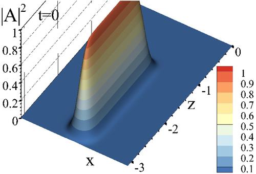
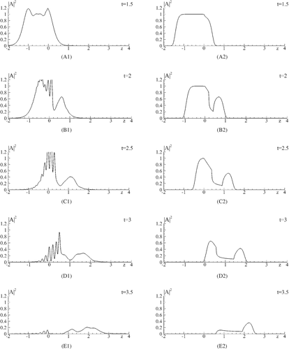
In Figure 2, the incident laser pulse distribution is depicted. Figure 3 demonstrates a formation and evolution of the free electron high concentration domain at the laser pulse interaction with a semiconductor, while the laser pulse profile is depicted in Figure 4. The high absorption domain appears with a certain delay with respect to the pulse front propagation. As a result, a part of the pulse firstly penetrates a semiconductor, and then a reflection of another part of the beam occurs from the domain boundary. We see that at a moment t = 1.5 (Figure 3(A1),(A2)) the laser pulse penetrates a semiconductor, and the free-electron high concentration domain starts to grow. At the time moment t = 2 (Figure 3(B1),(B2), Figure 4(B1)) this domain appears near the semiconductor face, and the traveling part of the optical beam reflects from the domain boundary. The reflected part of the beam propagates in the opposite direction to the incident laser pulse propagation direction. This leads to the interference between these beams and causes the intensity oscillation.
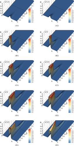
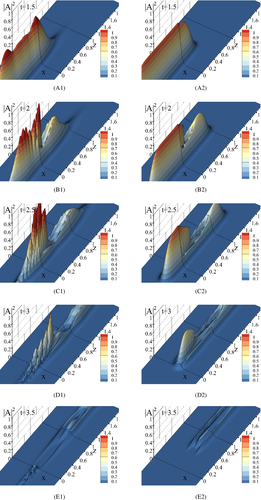
We can see the fundamental differences between the intensity distribution computed at taking into account or not the longitudinal diffraction for the description of the laser pulse propagation: if the longitudinal diffraction is under consideration, then the optical radiation reflected from the boundary of the contrast structure results in both the intensity oscillation (Figure 4(B1)–(D1)) and re-shaping of the free-electron high concentration domain (Figure 3(C1)–(D1)). If the computation of the laser pulse interaction with a semiconductor is provided without considering longitudinal diffraction, then there is not this optical radiation reflection and the domain profile differs from the previous case (Figure 3(B2)–(D2) and Figure 4(B2)–(D2)). In Figure 3(E1),(E2) and Figure 4(E1),(E2), a final stage of the process is depicted.
One more manifestation of the influence of the longitudinal diffraction on the laser pulse interaction with a semiconductor is demonstrated in Figure 5. We see a very pronounced difference between the profiles of the beams propagating with or without taking into account the longitudinal diffraction. The appearance of the reflected beam is the most interesting for us in the current paper. This part of the beam propagates in the direction opposite to the incident beam propagation direction. After three dimensionless units on time, the reflected beam passes distance, which is greater than one dimensionless spatial unit. As a rule, a computation is provided during about one thousand dimensionless units on time, we need to increase a domain size on z-coordinate by a few hundred times for a solution only a linear Schrödinger equation. This leads to enhancing many times a computation cost. That is why it is necessary to develop the ABCs for the problem under consideration. Let us stress that this problem is a typical one for nonlinear optics. Therefore, in the next paragraphs we discuss developing the adaptive ABCs for the 1D Schrödinger equation.
3 DEVELOPING ABC FOR 1D SCHRÖDINGER EQUATION
3.1 Statement of 1D problem and finite-difference scheme construction
The artificial boundaries in the spatial domain allow us to decrease the computational time. However, it could lead to the appearance of the spurious waves, reflected from the artificial boundary (red point-dash line in Figure 1), which can crucially change the computer simulation results. We believe that the adaptive ABCs can minimize the reflection wave and to avoid its influence on the problem solution.
Above , and , are the local group velocities and local wavenumbers, respectively, near the corresponding boundaries. Their values are chosen as constant at using non-adaptive ABCs, and they should be computed at using adaptive (time-dependent) ABCs.40 The sign of the group velocity νz in (15′) defines the beam propagation direction: it is moving in left direction if νz < 0, and in right direction if νz > 0. The question is what values of the local wavenumbers (local group velocities) are should be chosen to achieve the most effectiveness of the ABCs.
Using the following notations:
The Thomas algorithm is used for solving the stated above initial-boundary difference problems.
3.2 Computer simulation results at using non-adaptive ABCs
and mesh steps hz = 0.001, τ = 0.001 for the spatial domain at the solution of the problem (15′-17′). The incident laser pulse is located symmetrically with respect to the center of the spatial domain at the initial time moment. For definiteness, we should stress that the computations are provided using C++ realization of the finite-difference scheme (18′-20′) or (18″-20″) on multi-processors work-station Dell Precision T7910 2 x.
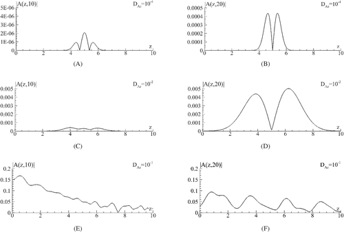
According to the set parameters, the beam propagates in the negative direction along z-axis. When the beam reaches the left artificial boundary, its certain part reflected, and it propagates in the positive direction of z-axis (Figure 6(A), (C), (E)). After reaching by this reflected (spurious) wave the right artificial boundary, then it also reflects. However, the reflected part of the beam may have a rather small amplitude compared with the maximal incident intensity (Figure 6(B),(D),(F)) if the diffraction of the beam is small enough (Figure 6(A),(B)), and these results are in agreement with the computational accuracy. The situation changes if the diffraction coefficient increases (Figure 6(C),(D)). In this case, the beam spreads due to diffraction action, and the beam local group velocity near the boundary differs from the wave packet velocity. As a result, a substantial part of the beam is reflected (Figure 6(E),(F)). Thus, the amplitude of the reflected wave depends strongly on the diffraction coefficient, and the non-adaptive ABCs are not effective enough under large diffraction.
Another illustration of the necessity of using adaptive ABCs at large diffraction of the beam is presented in Figure 8 by comparison of computational results obtained at the different (constant) local group velocities. We see that at the local group velocity (the green dashed line) the high efficiency of left ABC is observed in the vicinity of time point t = 5, but then its efficiency becomes worse (deviation from the reference solution increases). The same trend is observed for other values of the local group velocity (black solid and red dashed-point lines).
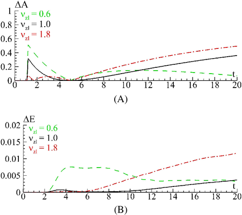
It should be mentioned that for the beam small diffraction, the ABCs with a constant value of the local group velocity may be applicable. This confirms by the computer experiments and follows from the obtained analytical expressions for the linear Schrödinger equation (we will discuss this below). Thus, based on the presented results, we can conclude that it is necessary to use the adaptive ABCs for decreasing the amplitude of the beam reflected from the artificial boundary. In this case, the local group velocities (local wavenumbers) must depend on both time and spatial coordinates.
3.3 Developing of the adaptive ABCs and computer simulation results
In our notation the local group velocity is defined from the equality: .
Let us mention that from formula (25) it is also seen that if is rather small, then a time coordinate does not influence the local wavenumber during computation in a long time interval, and ABCs with constant local wavenumbers (or local group velocity) provide the high computation accuracy. If has a big value, the local wavenumber varies essentially in time, and non-adaptive ABCs' efficiency decreases.
In Figures 9 and 10, the computer simulation results are presented at solving of the numerical problem (18″-20″) with the following parameters χ = 1, , az = 1, Lz = 10, Lt = 10, hz = 10−3, τ = 10−3. First of all, in Figure 9(A),(B) we depict and compare time-dependent computed using formula (26) for with P = Pz and analytical formula (25) for . It is clearly seen that both values of the local wavenumbers are in good agreement except a certain time interval, where values differ essentially regardless of whether we use ρ = 10−6 or ρ = 10−4. This computational inaccuracy appears because of the influence of the reflected beam on computation of the local wavenumbers. To decrease this impact, we propose to compute the integrals, involving in (24), not exact in the boundary node but at a certain distance from it, for example, in the point P ≤ Pz − 100. For P definition we use the criterion (27), but its maximal value is bounded by Pz − 100. The obtained results are shown in Figure 9(C),(D), and we see clearly, that they have an excellent correlation.
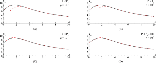
Thus, it could be inferred that the using integral ratio (24) for computation of the local wavenumber leads to the high accurate approximation of the real local wavenumber.
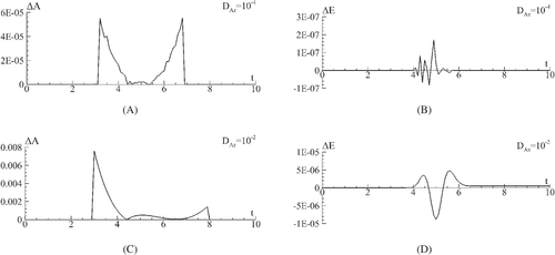
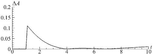
Furthermore, to estimate the correctness and accuracy of the proposed method for the adaptive ABCs computation, we also compare the reference solution with the solution computed at using the adaptive ABCs. As shown in Figure 10, the relative difference between the amplitude of the reflected part of the beam, which appears at using adaptive ABCs, and the reference solution's amplitude is about two times smaller than the best result obtained with non-adaptive ABCs (Figure 8(A)). Moreover, in this case ΔA does not grow in time as it is occurring at using non-adaptive ABCs.
3.4 Remark concerning the computational accuracy for different problem statements
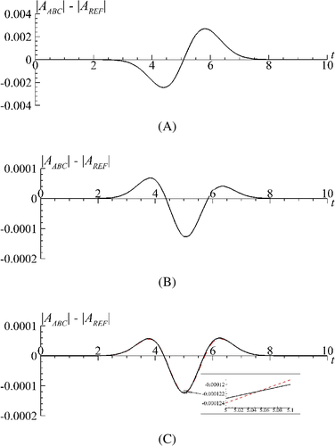
The statements of the 1D problem (15′-17′) and (15″-17″) are equivalent from a mathematical point of view. On the contrary, there are some peculiarities at the numerical solution of the problem. Analyzing Figure 11, we can see that at computing problem (15″-17″) the step of spatial mesh has a significant effect on obtained results: a difference between the amplitude of the reflected part of the laser pulse and amplitude of the reference solution computed on an extended domain decreases on order with decreasing hz from 10−3 to 10−4 (Figure 11(A),(B)). As it follows from Figure 11(C) at computing problem (15′-17′) obtained results do not depend critically on hz. It should be stressed that at solving the problem in the statement (15″-17″) with hz = 10−3 we obtained results with the same accuracy order as at solving (15′-17′) with hz = 10−4. This is an important feature of the problem under consideration and should be taken into account, especially at solving multidimensional problems.
3.5 Computer simulation results for 2D problem at using adaptive ABCs
4 CONCLUSIONS
We demonstrated that the longitudinal diffraction of a laser beam plays a fundamental role at the laser pulse propagation in a semiconductor under the occurrence of contrast structures of its characteristics. Its accounting leads to the appearance of the beam reflected from the boundaries of the laser-induced high absorption domain. We proved this statement by comparing the computer simulation results obtained for two mathematical models of the problem under consideration. Let us emphasize that the solving problem refers to the new field of nonlinear optics: nonlinear gradient optics.
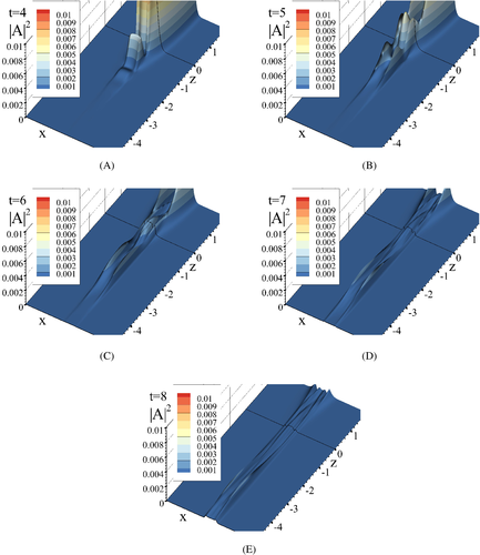
The appearance of the beam reflected from the contrast structure boundaries requires the extension of a spatial domain size that is governed by the time interval. It results in a decrease in computational efficiency. Therefore, it is necessary to use ABCs. We demonstrated that ABCs with constant parameters are not effective if the beam undergoes strong diffraction. To overcome these disadvantages of ABCs for the Schrödinger equation, the adaptive those were proposed. Their efficiency is demonstrated both on the solution of the 1D linear Schrödinger equation and the 2D problem of the laser pulse propagation in a semiconductor.
The developed method has wide applications for solution of various laser physics problems which are governed by a set of equations containing Schrödinger one.
ACKNOWLEDGMENT
Maria Loginova and Vladimir Egorenkov are thankful for the financial support to the Russian Science Foundation (Grant No. 19-11-00113).
Biographies

Vyacheslav Trofimov is a Professor at the South China University of Technology, Guangzhou, China. He received his PhD in Physics and Mathematics (with specialization in laser physics) in 1983 and Dr. Sc. in Physics and Mathematics (with specialization in Applied Mathematics) in 1995 from Lomonosov Moscow State University. Prof. Trofimov's research areas are mathematical models in physics, numerical methods, conservative finite-difference schemes, nonlinear optics and photonics, optical switching, terahertz spectroscopy and 3D printing. He has published over 600 research articles, most of them in high-rank international journals. Prof. Trofimov participated in more than 250 Russian and international conferences and was a member of scientific committees of 20 international conferences.

Maria Loginova received PhD in Physics and Mathematics (with specialization in mathematical modeling) in 2005 from Lomonosov Moscow State University. She is currently a scientific researcher in the faculty of Computational Mathematics and Cybernetics at Lomonosov Moscow State University. Her research interests are mathematical modeling of semiconductor plasma generation, optical bistability, and numerical methods for solving nonlinear PDEs. Dr. Loginova has more than 60 scientific publications including articles in high-rank international journals. She regularly participates in international conferences as a speaker.

Vladimir Egorenkov received a mathematics specialist degree from Lomonosov Moscow State University in 2014. He is currently working towards his PhD degree in Physics and Mathematics and is a predoctoral researcher in the faculty of Computational Mathematics and Cybernetics at Lomonosov Moscow State University. His research interest is the development of conservative finite-difference schemes for computer modeling of laser pulse interaction with the nonlinear medium. He has more the 30 scientific publications, among them 13 journal articles.


