Driving inward growth of lithium metal in hollow microcapsule hosts by heteroatom-controlled nucleation
Abstract
The application of Li metal anodes in rechargeable batteries is impeded by safety issues arising from the severe volume changes and formation of dendritic Li deposits. Three-dimensional hollow carbon is receiving increasing attention as a host material capable of accommodating Li metal inside its cavity; however, uncontrollable and nonuniform deposition of Li remains a challenge. In this study, we synthesize metal–organic framework-derived carbon microcapsules with heteroatom clusters (Zn and Ag) on the capsule walls and it is demonstrated that Ag-assisted nucleation of Li metal alters the outward-to-inward growth in the microcapsule host. Zn-incorporated microcapsules are prepared via chemical etching of zeolitic imidazole framework-8 polyhedra and are subsequently decorated with Ag by a galvanic displacement reaction between Ag+ and metallic Zn. Galvanically introduced Ag significantly reduces the energy barrier and increases the reaction rate for Li nucleation in the microcapsule host upon Li plating. Through combined electrochemical, microstructural, and computational studies, we verify the beneficial role of Ag-assisted Li nucleation in facilitating inward growth inside the cavity of the microcapsule host and, in turn, enhancing electrochemical performance. This study provides new insights into the design of reversible host materials for practical Li metal batteries.
1 INTRODUCTION
In recent years, the demand for batteries with high energy densities has increased significantly, along with the growing demand for electric vehicles. Li metal has garnered considerable research attention as a promising anode material for advanced rechargeable batteries because of its high theoretical specific capacity (3860 mAh g−1) and low electrochemical equilibrium potential (−3.040 V vs. standard hydrogen electrode [SHE]).1, 2 However, Li metal batteries still have several hurdles in their practical application because Li metal anodes experience infinite volume expansion, which induces continuous rupture and formation of solid-electrolyte interphase (SEI) layers. This leads to electrolyte consumption and corrosion of Li metal, resulting in a low Coulombic efficiency and poor cycling performance. In addition, the uncontrollable dendrite growth of Li metal may cause early battery failure and safety issues.3-5
The main strategies for addressing the problems with Li metal are as follows: (1) construction and engineering of artificial SEIs consisting of various substances (inorganics, organics, polymers, and their hybrids)6-9; (2) optimization of electrolyte additives to form highly ionic conductive SEI layers10, 11; and (3) rational design of three-dimensional (3D) porous hosts.12-15 In particular, introducing 3D host materials is a promising strategy for alleviating the severe volume changes of metallic Li because the host structure can trap Li deposits inside its pores and provide abundant reaction sites for Li+ reduction.16
Among the various 3D host materials under development, carbon-based materials with hollow structures have been investigated extensively because of their attractive features. The enlarged void space (cavity) of the hollow hosts can accommodate a significant amount of Li deposits while inhibiting volume changes during plating–stripping cycles.17 In addition, according to Sand's model, a reduced local current density, originating from the large surface area of carbon, can inhibit the formation of Li dendrites.18, 19 Hollow carbon possesses a much lower density than metal-based materials, thereby increasing the specific capacity and energy density. However, the lithiophobic nature of carbon, combined with its high resistance to Li+ transport through nanopores on the walls, significantly hinders the formation of Li deposits inside the cavity. Li may nucleate on the outer surface of the carbon particles in a nonuniform manner, thereby causing the growth of Li dendrites and electrochemically inactive Li deposits.17, 20 To resolve these issues, elaborate material structures have been proposed, such as hollow spheres with embedded lithiophilic Ni2P seeds, hierarchical root-like hollow fibers with interconnected structures, and double-shelled hollow scaffolds with preloaded sulfur as an electrolyte additive.21-23
Furthermore, carbon-based electrodes with Ag were widely used as anodes for reversible storage of Li. Ag can promote the reaction kinetics of the Li plating reaction by forming a solid solution with Li metal, thereby greatly reducing the energy barrier for the nucleation and subsequent growth of Li. Thus, the Ag composite anode was extensively investigated for batteries with Li metal anodes, including all-solid-state batteries.24, 25 In the previous study, we reported carbonized zeolitic imidazole framework-8 (ZIF-8) particles with galvanically displaced Ag as 3D carbon host structures and demonstrated that the atomic Ag clusters promote the reversible plating-stripping of Li metal in the internal micropores of the carbon host.26 However, such a “solid” host structure might be of less practical significance in terms of the energy density of batteries because Li metal can be accommodated only in micropores of the carbon host.
To increase the capacity and energy density of the carbon host, herein, we report metal–organic framework (MOF)-derived “hollow” microcapsule carbon hosts (MCCHs) with heteroatom clusters on the capsule walls, in which atomic Ag clusters drive selective nucleation and inward growth of Li metal. The cavity inside the microcapsule host, which was generated by etching with tannic acid (TA), provides large void spaces for Li metal storage.15 Atomic Ag clusters decorated by a galvanic displacement reaction serve as preferential nucleation sites with a reduced energy barrier and promote the inward growth of Li metal in the cavity while suppressing nonuniform Li plating on the outer surface. The nucleation and growth behaviors of Li metal were investigated comprehensively by electrochemical and computational studies, demonstrating that the synergetic role of Ag-controlled nucleation and hollow architectures improves the electrochemical performance.
2 EXPERIMENTAL SECTION
2.1 Synthesis of MCCHs
The solutions of 11.2 g of zinc acetate dihydrate (Zn(CH3CO2)2·2H2O, 99%, Sigma-Aldrich) and 3 g of 2-methylimidazole (C4H6N2, 99%; Sigma–Aldrich) were prepared by dissolving those separately in 50 mL of deionized (DI) water. After stirring for 2 h, Zn(CH3CO2)2·2H2O solution was added to the 2-methylimidazole solution and stirred at room temperature for 30 min. After 24 h, the precipitates were centrifuged, washed several times with distilled water, and dried at 60°C overnight. For the synthesis of hollow ZIF-8, 0.24 g of the prepared ZIF-8 was dispersed in 120 mL DI water by ultrasonication and vigorous stirring, while 1.2 g TA (Sigma–Aldrich) was dissolved in 120 mL of DI water. The TA solution was then gradually dropped into the ZIF-8 dispersion under continuous stirring, followed by aging for 5 min. Subsequently, the hollow ZIF-8 particles were collected by centrifugation, washed with DI water and methanol several times, and dried at 60°C. Finally, the obtained materials were placed in a tube furnace and heated to 800°C for 2 h under Ar at a rate of 2°C min−1 to yield MCCH particles.
2.2 Synthesis of Ag-MCCHs
The Ag-incorporated MCCHs were synthesized using a facile galvanic displacement method. The MCCH particles (200 mg) were dispersed in 40 mL ethanol by ultrasonication for 10 min to form a uniform suspension. AgNO3 (40 mg; 99%; Kojima Chemicals) was dissolved in 40 mL ethanol under vigorous stirring for 20 min. The AgNO3 solution was then added to the MCCH suspension to initiate galvanic displacement. The mixed suspension was then stirred for 12 h at room temperature. Finally, the product was collected by centrifugation, washed with distilled water, and dried overnight at 60°C.
2.3 Characterization
The morphologies of the samples were characterized using a field-emission scanning electron microscope (FE-SEM) (Hitachi S4800) and a high-resolution transmission electron microscope (HR-TEM) (Hitachi HF-3300). The specific surface area and pore volume were measured using an adsorption apparatus with the N2 adsorption–desorption method at 77 K using a porosity analyzer (ASAP2020). X-ray photoelectron spectroscopy (XPS) (ESCALAB 250Xi) was performed on the samples to detect the chemical states of C, N, Zn, and Ag. Raman spectra were obtained using a Raman spectrometer (Nicolet Almega XR).
2.4 Electrochemical measurements
Electrochemical measurements were conducted at room temperature using a coin-type test cell (CR2032) with Li metal as the counter electrode. The cells were then assembled in an Ar-filled glove box. A conventional slurry-casting method was used to fabricate the electrodes. The slurry consisted of a carbon host (80 wt%), Super P as a conductive additive (10 wt%), polyvinylidene fluoride as a binder (10 wt%), and 1-methyl-2-pyrrolidone as a solvent. The slurry was dried at 120°C under vacuum for 2 h and calendared before use. The thickness was adjusted to 20–25 μm by calendering and the loading mass was controlled to 0.7 mg cm−2 (density: 0.3 mg cm−3). A Celgard separator was used, and the electrolyte consisted of 1 M lithium bis(tri-fluoromethanesulfonyl)imide in a cosolvent of dimethyloxolane and dimethoxyethane (volume ratio: 1:1) with 1 wt% lithium nitrate as an additive. To standardize the measurements, 100 μL of the electrolyte was used in each coin cell. Before the electrochemical tests, the cells were preconditioned by three cycles of the formation steps in a voltage range of 0–2.0 V versus Li/Li+ with a current density of 0.2 mA cm−2. The nucleation overpotentials were characterized by galvanostatic plating at 0.4 mA cm−2, with an areal capacity of 2.0 mAh cm−2. To further investigate the nucleation behaviors, three-electrode cells were assembled with the Li reference electrode, and chronoamperometry was performed in a voltage range of 10 to −250 mV versus Li/Li+. Cyclic voltammetry was performed from −0.5 to 3.0 V versus Li/Li+ at a scan rate of 0.5 mV s−1. For the rate capability tests and cycle test, the cell was prepared by plating 2.0 mAh cm−2 of Li at 0.2 mA cm−2.
2.5 Modeling
3 RESULTS AND DISCUSSION
As shown in Figure 1A, Ag-MCCH was prepared by chemical etching, pyrolysis, and galvanic displacement. First, ZIF-8 was obtained as the precursor for fabricating MCCH by the precipitation reaction between zinc acetate dihydrate and 2-methylimidazole.27 Second, the obtained ZIF-8 particles were chemically etched by TA using synergetic interactions between the MOFs and polyphenols to form hollow ZIF-8.28 Third, hollow ZIF-8 was pyrolyzed at 800°C under an Ar atmosphere to produce MCCH.29 During pyrolysis, atomic Zn clusters in the hollow ZIF-8 are converted to ZnO, followed by thermal reduction to Zn.30 Given that the pyrolysis temperature is lower than the boiling point of Zn (908°C), residual Zn clusters exist in MCCH, and then, they are replaced with Ag during the subsequent galvanic displacement process. Finally, a displacement reaction between Zn and Ag+ was performed at room temperature to incorporate Ag into the capsule walls of MCCH.31, 32 The driving force of the galvanic displacement between Zn and Ag+ (Zn + 2Ag+ ↔ Zn2+ + 2Ag) is the difference in the electrochemical potential of Zn/Zn2+ (−0.76 V vs. SHE) and Ag/Ag+ (+0.86 V vs. SHE).
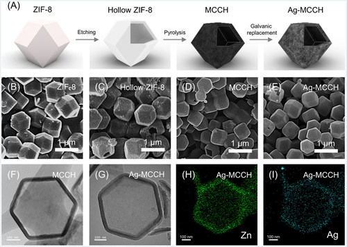
The morphology and microstructure of the synthesized materials were analyzed using an FE-SEM and an HR-TEM (Figures 1B–G and S1). The rhombic dodecahedral morphology of pristine ZIF-8 was maintained during the consecutive processing steps for the preparation of hollow ZIF-8, MCCH, and Ag-MCCH, whereas the particle size was reduced from approximately 600–450 nm after pyrolysis. Figure 1F clearly shows the large cavity in the hollow ZIF-8 particles with thin shells (approximately 30 nm), indicating successful chemical etching by TA. In addition, from the elemental mapping images obtained by energy-dispersive X-ray spectroscopy (EDS) combined with high-angle annular dark-field scanning transmission electron microscopy (HAADF-STEM), the presence of Zn in MCCH (Figure S2) and Zn/Ag in Ag-MCCH (Figure 1H,I) was confirmed. These results indicate that metallic Zn in MCCH was partially replaced with Ag after the galvanic displacement reaction.
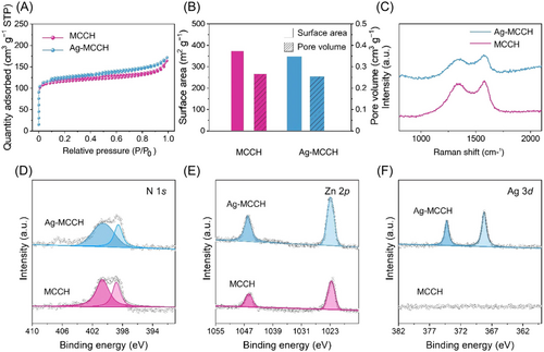
Figure 2A shows the N2 adsorption–desorption isotherms acquired for MCCH and Ag-MCCH. The specific surface areas calculated by Brunauer–Emmett–Teller analysis were 372.3 and 348.1 m2 g−1 for MCCH and Ag-MCCH, respectively, which are significantly higher than those of carbonized ZIF-8 without etching (225.5 m2 g−1).26 The high specific surface area of the microcapsules can lower the local current density of the host during Li plating–stripping, preventing dendritic growth of Li.19 In addition, specific pore volumes were calculated from Barrett–Joyner–Halenda analysis. The specific pore volumes of MCCH (0.27 cm3 g−1) and Ag-MCCH (0.25 cm3 g−1) were greater than that of carbonized ZIF-8 (0.13 cm3 g−1) without etching (Figures 2B and S3). The Raman spectra of MCCH and Ag-MCCH showed two typical bands located at 1350 and 1600 cm−1, ascribed to the defect-induced D and graphitic G bands of carbon, respectively (Figure 2C). The peak intensity ratios of D and G bands (ID/IG) of MCCH and Ag-MCCH were 0.948 and 0.938, respectively, indicating that the graphitization degree of the microcapsules was maintained after the galvanic displacement reaction.33 The chemical state and composition of the microcapsules were studied using XPS (Figure 2D–F). The N 1s peaks were deconvoluted into pyrrolic and pyridinic N peaks, which are known to improve the electrical conductivity of the amorphous carbon matrix.34 The Zn 2p spectrum exhibits two distinctive peaks at 1023.1 and 1046 eV, confirming the existence of metallic Zn constituents in both MCCH and Ag-MCCH.35 The two peaks in the Ag 3d spectrum of Ag-MCCH confirmed that galvanically displaced Ag clusters existed in metallic form, which was further supported by the X-ray diffraction patterns (Figure S4).36
To investigate the Li storage behavior of MCCH and Ag-MCCH, electrochemical tests were conducted using half-cells with Li foil as the counter electrode (Figure 3). For the fabrication of host electrodes, a conventional slurry-casting method was employed (Figure S5A,B). Prepared host electrodes exhibited no fracture or delamination after bending, demonstrating their mechanical robustness (Figure S5C). To understand the nucleation and growth behaviors, the potentiostatic current transients, that is, current (i) versus time (t), were analyzed (Figure 3A,B). To minimize the corruption of the current from the SEI formation and lithiation of carbon, the cells were charged to 10 mV versus Li/Li+ at 0.2 mA cm−2 and maintained until the current decreased to 10 μA to complete the lithiation of carbon hosts.37 The potential step of −0.25 V was then applied to initiate Li plating. According to the measured current transients, Li plating in both MCCH and Ag-MCCH followed instantaneous nucleation (Region 1) and diffusion-controlled growth (Region 2) mechanisms (Figure 3A).
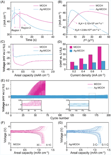
The nucleation rates (N0A) were calculated from the linear fitting of the transient current curve in Region 1 using Equation (4). The higher N0A value of Ag-MCCH (2.84 × 1010 cm−2 s−1) than that of MCCH (2.12 × 109 cm−2 s−1) is owing to the facile nucleation kinetics promoted by galvanically introduced lithiophilic Ag clusters (Figure 3B).
Figure 3C shows the voltage profiles of MCCH and Ag-MCCH during galvanostatic Li plating at a current density of 0.4 mA cm−2. Benefiting from the atomic Ag clusters, the half-cell with Ag-MCCH exhibited a smaller nucleation overpotential (4.8 mV), corresponding to the nucleation energy barrier, compared to that of MCCH (8.4 mV).39 The reduced nucleation barrier of Ag-MCCH implies that lithiophilic Ag clusters serve as selective nucleation sites, which play a vital role in governing the subsequent growth behavior.40 In addition, cyclic voltammetry was conducted to measure the exchange current density for Li plating (Figure S6). Ag-MCCH exhibited a significantly higher exchange current density (26.11 mA cm−2) than its counterpart (1.85 mA cm−2), indicating faster kinetics for Li plating.41, 42 The electrochemical performances of microcapsule hosts were evaluated by the plating–stripping cycling test at various current densities from 0.2 to 1.0 mA cm−2 with a fixed capacity of 0.2 mAh cm−2 (Figure 3D). Before the test, the host electrodes were preplated at 2.0 mAh cm−2. The overpotentials of the Ag-MCCH cell remained lower than those of the MCCH cell, which exhibited a rapid increase, particularly during high-rate operations. Furthermore, as shown in Figures 3E and S7, Ag-MCCH exhibited a long lifespan during repeated plating–stripping cycles, when compared to MCCH. The electrochemical performance of Ag-MCCH was compared with those of previous works in Table S1.43-46
Moreover, full cells were assembled with LiFePO4 cathode and host electrodes to assess the feasibility of Ag-MCCH for Li metal batteries (Figure 3F,G). Before cell assembly, host electrodes were preplated with the areal capacity of 2 mAh cm−2 in half cells with Li metal as a counter electrode. The [Ag-MCCH || LiFePO4] cell shows improved rate capability in comparison to the [MCCH || LiFePO4] cell, exhibiting a larger discharge capacity of 155.2 mAh g−1 at a high charging current of 3 C. The discharge capacity of the [Ag-MCCH || LiFePO4] cell was recovered to 164.7 mAh g−1 when the charging rate was returned to 0.5 C after high-rate cycles, evidencing the superior reversibility of Ag-MCCH compared to MCCH. Also, we conducted 0.5 C charge–discharge tests after the rate capability test. The full cell with the Ag-MCCH anode exhibited better capacity retention than that of MCCH (Figure S8).
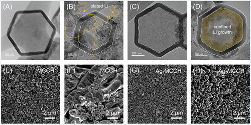
To elucidate the improved rate capability and cycling stability of Ag-MCCH in terms of Li nucleation behavior, ex situ microstructural analyses after Li plating were conducted using HR-TEM and FE-SEM (Figure 4). HR-TEM images of Li plating show that Li was unevenly plated on the outer shell of MCCH, which could be easily transformed to “dead” Li deposits during Li plating–stripping (Figure 4A,B). In contrast, Li plating on Ag-MCCH led to the inward growth of Li metal inside the cavity, effectively utilizing a porous structure and preventing the growth of Li dendrites (Figure 4C,D). The HAADF-STEM micrographs on plated MCCHs further evidence that Li grows inward in Ag-MCCH, whereas the outer Li is plated on the wall of MCCH (Figure S9). The uneven plating of Li on the outer shell of the MCCH eventually triggered the growth of Li dendrites, which may cause internal short-circuiting, leading to safety issues (Figure 4E,F). In contrast, the clear surface of the Ag-MCCH electrode upon Li plating indicates that the Li deposits were successfully confined in the cavities, improving the rate capability and cycling performance (Figure 4G,H). To investigate the effect of the Ag amount on the Li plating behavior, we performed galvanic displacement by increasing the concentration (2 g L−1) of the reaction solution; however, agglomerated Ag nanoparticles were formed (Figure S10A), and the plated Li was detected on the electrode even at low capacity of 0.5 mAh cm−2 (Figure S10B). To increase the amount of residual Zn and thus to increase the amount of galvanically displaced Ag, moreover, the TA concentration for the etching process was reduced from 5 to 2.5 g L–1. However, the resulting ZIF showed an incompletely etched shape (Figure S10C).
To demonstrate the role of atomic Ag clusters in regulating the initial nucleation and subsequent growth behavior of Li, electrochemical simulations were conducted based on finite element analysis using COMSOL Multiphysics software (Figure 5).47 For the simulations, a domain with a Li metal electrode, an electrolyte, and a porous electrode with a host particle was constructed (Figure S11). The distribution of interfacial reaction current density in MCCH and Ag-MCCH particles was predicted by the single-particle 3D simulation. Furthermore, to imitate the cross-sectional morphology of the MOF-derived microcapsules for the 2D simulation, the geometry of the host particle was set as a hexagon with SEI layers located on both sides of the wall.43 The lithiophilic character of Ag was replicated by the high exchange current density applied to the wall in both 2D and 3D models. In addition, the slow kinetics of Li+ transport through the SEI layers was considered with a low ionic conductivity and diffusion coefficient in the 2D simulation model.
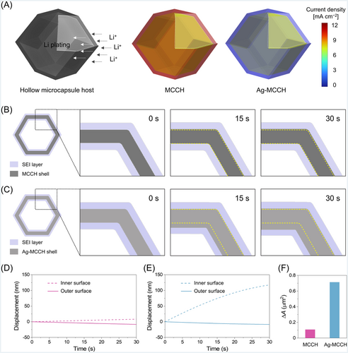
The 3D modeling results demonstrate that the inner wall of Ag-MCCH exhibits much higher current density than its outer surface, promoting preferential Li storage in its hollow cavity (Figure 5A). However, due to the ion transport resistance through the pores in the shell, the outer surface of the MCCH particle becomes the preferential site for Li plating, hindering Li storage in its hollow cavity. Figure 5B,C shows the morphological evolution of MCCH and Ag-MCCH, respectively, upon Li plating at 0.1 mA cm−2. The thickness of the MCCH wall remains unchanged upon Li plating because Li is barely plated on the host but deposited on the top surface of the porous electrode (Figure 5D). In contrast, Figure 5C clearly shows the inward displacement of the walls upon Li plating, confirming the beneficial role of Ag in driving the inward growth inside the cavity (Figure 5E). Figure 5F shows the increases in the cross-sectional area of the shell (ΔAshell) upon Li plating, which denotes the amounts of Li plated in the host particle. Compared to the MCCH, a greater amount of Li was plated on the Ag-MCCH particles owing to the Ag-assisted nucleation and subsequent growth of Li. The simulations suggest the inward growth behavior of Li only when the inner wall of Ag-MCCH is assumed to have a higher activity than the outer wall. Simulations were performed using another Ag-MCCH system, in which a high exchange current density was employed on both sides of the capsule wall. The host particle exhibited inward and outward thickening of the walls, which was not consistent with the experimental results (Figure S12). These results indicate that galvanically displaced Ag in Ag-MCCH is predominantly distributed toward the inner wall, facilitating the selective nucleation of Li inside the microcapsules.
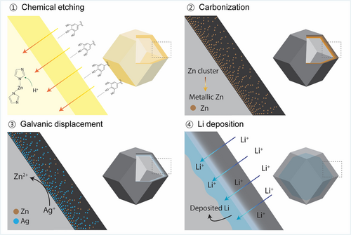
Figure 6 shows the synthesis–structure–property relationship of Ag-MCCH. Although each of the processes used for material synthesis has been known in the literature,15 the TA-assisted etching combined with galvanic displacement of Ag results in the formation of a unique host structure. According to conventional knowledge, the high ionic transport resistance of micropores on the lithiophilic walls of the hollow carbon host causes preferential nucleation and growth of Li on the outer surface and/or in the internal pores of the walls.48 During the chemical etching process, the organic linkers of ZIF-8 are decomposed by the released H+ and partially displaced by the phenol groups in TA, forming metal-phenolic frameworks that result in the formation of hollow ZIF-8. The TA molecules adsorbed on the outer shell of the hollow ZIF-8 decompose to amorphous carbon during pyrolysis, and thus a concentration gradient of Zn evolves within the wall.15, 27 In the subsequent galvanic displacement reaction, Ag was deposited on the Zn-rich inner walls, leaving the Zn-deficient outer walls less lithiophilic. As a result, the synthesis approach based on the combined TA-assisted etching and galvanic displacement enables the inward growth of Li within the cavity.
4 CONCLUSION
MOF-derived hollow carbon microcapsules with lithiophilic heteroatom clusters were proposed as host materials for reversible Li metal storage. Galvanically displaced Ag in Ag-MCCH reduces a nucleation barrier to boost the reaction kinetics of Li plating, resulting in improved electrochemical performances. The microstructural and computational studies revealed that the Ag-assisted nucleation on the inner wall with the increased nucleation rate enables inward growth of Li in Ag-MCCH, inducing further uniform Li deposition. Consequently, owing to the synergetic effect of Ag-assisted Li nucleation and elaborate hollow structures, Ag-MCCH exhibits an extended cycle life with low overpotentials during Li plating–stripping cycling. This study provides new insights into the development of hollow host materials with controlled Li plating kinetics for reversible Li metal anodes.
ACKNOWLEDGMENTS
This research was supported by the National Research Foundation (NRF-2018R1A5A1025594 and NRF-2022M3J1A1062644), Republic of Korea.
CONFLICT OF INTEREST STATEMENT
The authors declare that there are no conflicts of interests.


