Reshaping Li–Mg hybrid batteries: Epitaxial electrodeposition and spatial confinement on MgMOF substrates via the lattice-matching strategy
Abstract
The emergence of Li–Mg hybrid batteries has been receiving attention, owing to their enhanced electrochemical kinetics and reduced overpotential. Nevertheless, the persistent challenge of uneven Mg electrodeposition remains a significant impediment to their practical integration. Herein, we developed an ingenious approach that centered around epitaxial electrocrystallization and meticulously controlled growth of magnesium crystals on a specialized MgMOF substrate. The chosen MgMOF substrate demonstrated a robust affinity for magnesium and showed minimal lattice misfit with Mg, establishing the crucial prerequisites for successful heteroepitaxial electrocrystallization. Moreover, the incorporation of periodic electric fields and successive nanochannels within the MgMOF structure created a spatially confined environment that considerably promoted uniform magnesium nucleation at the molecular scale. Taking inspiration from the “blockchain” concept prevalent in the realm of big data, we seamlessly integrated a conductive polypyrrole framework, acting as a connecting “chain,” to interlink the “blocks” comprising the MgMOF cavities. This innovative design significantly amplified charge-transfer efficiency, thereby increasing overall electrochemical kinetics. The resulting architecture (MgMOF@PPy@CC) served as an exceptional host for heteroepitaxial Mg electrodeposition, showcasing remarkable electrostripping/plating kinetics and excellent cycling performance. Surprisingly, a symmetrical cell incorporating the MgMOF@PPy@CC electrode demonstrated impressive stability even under ultrahigh current density conditions (10 mA cm–2), maintaining operation for an extended 1200 h, surpassing previously reported benchmarks. Significantly, on coupling the MgMOF@PPy@CC anode with a Mo6S8 cathode, the assembled battery showed an extended lifespan of 10,000 cycles at 70 C, with an outstanding capacity retention of 96.23%. This study provides a fresh perspective on the rational design of epitaxial electrocrystallization driven by metal–organic framework (MOF) substrates, paving the way toward the advancement of cutting-edge batteries.
1 INTRODUCTION
Amid the escalating demand for next-generation energy storage solutions, batteries featuring light metals like sodium (Na) and magnesium (Mg) as anode materials have garnered considerable success.1-3 Notably, within this landscape, Mg-ion batteries (MIBs) have emerged as focal points of attention, owing to their exceptional attributes such as high gravimetric and volumetric capacities (2205 mAh g−1 and 3833 mAh cm−3), a substantial redox potential (−2.37 V vs. the standard hydrogen electrode), and cost-effectiveness.4-9 Nevertheless, the development of MIBs is severely hindered by ineffective cathode materials, higher charge density of Mg2+ ions, and poor intercalated/deintercalated kinetics.10-12 The potential architecture of Li–Mg hybrid batteries (LMBs) was an effective alternative, with a Mg anode and the Li intercalation/deintercalation cathodes.13-15 The combination of Mg metal anodes and Li+ ion cathodes endows the battery with excellent electrochemical kinetics to ensure outstanding rate and cycle performance. Moreover, the positive effect of Li salts has also been reported to enhance the ion transport kinetics.16 Nevertheless, fibrous Mg dendrites have been obviously detected on the Mg anode, which might pierce the separator.17 Furthermore, the presence of Mg dendrites could exacerbate issues such as corrosion and passivation, impeding the seamless movement of Mg2+ ions. As a consequence, the challenges stemming from Mg dendrites within LMBs persisted without resolution, potentially culminating in the occurrence of internal short circuits.
Considerable efforts have been made to inhibit Mg dendrites, such as fabrication of the protective solid electrolyte interface, construction of three-dimensional (3D) hosts, and optimization of liquid/solid-state electrolytes.18-24 According to Sand's model, design of 3D hosts or scaffolds for a Mg metal anode could reduce the local current density and prevent volume changes, so as to inhibit the growth of Mg dendrites during repeated cycles.25, 26 Song et al.'s27 group designed a 3D VNCA@C substrate, with N- and O-doped carbon fiber, to serve as a Mg anode, which could homogenize the current distribution and promote uniform deposition of Mg. Nonetheless, 3D scaffolds with sophisticated and magnesiophilic surfaces are still very much required to further improve the electrochemical performances of LMBs. Furthermore, the fundamental mechanism governing the process of Mg electrodeposition/dissolution onto the engineered host remains in its nascent stages.
Epitaxial electrodeposition has been carried out with the aim of promoting homogeneous deposition in rechargeable Zn- and Li-ion batteries.28-31 During the epitaxial electrodeposition procedure, an epilayer interphase with low lattice parameters that was a misfit with the substrate was designed to facilitate heteroepitaxial nucleation under low residual stresses. The well-aligned graphene-modified electrode was developed to ideally match the Zn metal, driving Zn deposition with the planform and locked crystallographic orientation.32 In addition, the homogeneous modified coatings were fabricated to enable homoepitaxial growth of Li metal during the electrodeposition procedure.31 However, the reported layers used for epitaxial electrodeposition were usually 2D nanosheet materials, such as graphene, SnS2, and so forth, with a relatively low specific surface area. In this vein, the hierarchically porous electrode was anticipated to promote heteroepitaxial electrodeposition through an interplay of factors, including reduction of local current density and facilitation of uniform deposition while maintaining a fixed orientation.
Metal–organic frameworks (MOFs), with abundant pore structures and functional groups, can be expected to offer enriched nucleation sites and a well-defined transmission channel, thus promoting homogeneous and reversible metal deposition. Moreover, the space-confinement effect generated by MOFs could promote preferential growth of Mg atoms in the successive nanochannels. Nevertheless, to the best of our knowledge, no studies on epitaxial electrodeposition driven by MOF matrices have been reported, whether in Li, Zn, Mg, or other metal ion batteries. Furthermore, the precise epitaxial mechanisms governing the atomic-scale regulation of Mg atoms by the MOF matrix remain a topic of ongoing research and are yet to be definitively established.
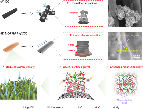
In this work, for the first time, we pioneered an innovative approach to achieve epitaxial electrocrystallization of Mg atoms onto a MgMOF substrate. Our chosen MgMOF substrate had the advantages of prominently exposed magnesiophilic centers and a remarkably low lattice-misfit rate with Mg, thereby facilitating the process of heteroepitaxial electrodeposition as illustrated in Scheme 1. Furthermore, the orchestrated interplay of a periodic electric field and intricately arranged nanochannels within the MgMOF induced a space-confinement effect, resulting in precise and homogeneous nucleation of Mg at the molecular scale. Specifically, on the basis of the “blockchain” concept in big data, conductive N-rich polypyrrole (PPy) was ingeniously designed as the “chain” to interlink the “blocks” of the MgMOF cavity to enhance the charge transfer and electrochemical kinetics. The as-fabricated MgMOF@PPy@CC host facilitated heteroepitaxial Mg electrodeposition, showing excellent Mg electrostripping/plating kinetics and remarkable cycle performance. Surprisingly, the symmetrical cell assembled with the MgMOF@PPy@CC electrode could work at an ultrahigh current density (10 mA cm–2) stably for 1200 h, outperforming previously reported results. Most importantly, integration of the MgMOF@PPy@CC anode with a Mo6S8 cathode yielded a composite battery system that showed excellent performance under rigorous conditions. Specifically, the battery showed unparalleled stability, enduring over 10,000 charge–discharge cycles at 70 C while retaining an exceptional capacity of 96.23%. This work introduces a novel and transformative outlook on the methodical design of epitaxial electrocrystallization, and hence paves the way towards fabrication of next-generation energy storage technologies.
2 RESULTS AND DISCUSSION
2.1 Design principles
- (1)
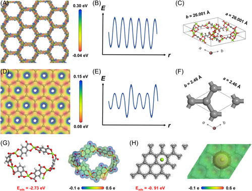
The electrostatic potential on the matrix is considered to be an essential factor to facilitate uniform Mg electrodeposition, thus preventing dendrite-induced short circuit. The electrostatic potential arrangements of both graphite and MgMOF were studied based on density functional theory (DFT) calculations. As for the graphite, which was made up of periodical sp2 C atoms, a uniform electrostatic potential field could be achieved (Figure 1D). Despite this, the thermal variability and inevitable defects that could emerge during practical applications could lead to a nonperiodic electrostatic potential field, thus inevitably inducing dendritic Mg electrodeposits (Figure 1E). Ionic-crystal MgMOF, with a periodic 3D structure, was chosen in this work, due to the small lattice misfit with Mg (discussed below) and the uniformly distributed electrostatic-potential field (Figure 1A,B). Moreover, because of the larger electronegativity difference between metal ions and ligands, MgMOF showed a higher amplitude of electrostatic potential than the graphite sheet. As a consequence, the Mg2+ ions could be adsorbed, thus promoting homogeneous Mg deposition.
- (2)
Low lattice misfit between the matrix and Mg is a critical prerequisite to promoting epitaxial Mg electrodeposition.32 The substrate should show similar atomic arrangement to and small lattice misfit as Mg, which was endowed with the following lattice parameters: a = b = 3.220 Å, c = 5.230 Å, α = β = 90°, and γ = 120° (Figure S1).33 Considering these requirements, MgMOF was selected as an attractive candidate, with the following lattice parameters: a = b = 26.001 Å, c = 6.827 Å, α = β = 90°, and γ = 120° (Figure 1C);34 however, graphite showed rather poor lattice match with Mg crystal, as high as 12.73%, and failed to create a coherent lattice interface due to the large lattice strain (Figure 1F).
- (3)
The substrate, endowed with a magnesiophilic nature and successive nanochannels with the space-confinement effect, is also a crucial factor for homogeneous Mg electrodeposition. In general, the powerful interactions between Mg and the substrate could effectively lower the nucleation barrier, thereby achieving uniform Mg electrodeposition. The charge density distribution showed a remarkable electron transfer from the Mg atom to MgMOF (Figure 1G, pictured right). Thid result reconfirmed the strong Mg–MgMOF interaction, which was possibly due to the empty O 2p orbitals in MgMOF. In comparison, less charge transfer and poor interaction were observed between the graphite and Mg (Figure 1H, pictured on the right). As shown in Figure 1G,H, the MgMOF crystal showed a strong adsorption energy of −2.73 eV, while that of the graphite was −0.91 eV. The synergism of strong magnesiophilic sites and the spatial-confined nanostructure not only improves the ion diffusion kinetics but also promotes homogeneous Mg nucleation and electrodeposition.
2.2 Fabrication and characterizations
The synthetic steps for fabricating the MgMOF@PPy@CC electrode have been described in detail in the experimental section. Briefly, MgMOF was grown in situ on carbon cloth (CC) through the hydrothermal reaction. Then, the purified pyrrole monomer was filled and polymerized in the activated MgMOF cavity. The successful synthesis of the uniformly distributed MgMOF@CC was attributed to the optimized procedure. With the conventional preparation process, the bulk MgMOF crystals with a disorganized orientation were decorated on the CC, which failed to provide the periodic electrostatic potential field (Figure S2). The reason might be ascribed to the low deprotonation rate of 2,5-dihydroxyterephthalic acid. Thus, some modulators, such as the salicylic acid (SA), triethylamine, hexadecyl trimethyl ammonium bromide, and Tween 80, were optimized to serve as morphological adjusters to tune the growth direction of MgMOF on the CC. The results are shown in Figures S3 and 2C, and the SA modulator showed the best performance (Figure 2C), which was chosen in the following experiment. When the mixed solvent of dimethylformamide (DMF)/ethanol/SA was used without a H2O solvent, the bulk MgMOF particles agglomerated directly in the solvent without growing on CC, as shown in Figure S4. The result indicated that water also played a significant role in confining the growth orientation through absorption on the metal coordination sites, in addition to acting as an effective stripping agent during the solvothermal reaction process. The reaction solvent was carefully optimized and only the selected solvents with DMF/ethanol/H2O/SA could realize uniformly distributed MgMOF@CC. MgMOF fabrication on the CC substrate was also thoroughly modulated by regulating the reactant concentrations of MgMOF (Table S1). When we synthesized MgMOF@CC-1, only a small amount of MgMOF grew on the CC, because of the insufficient source materials (Figure S5A). Then, the reactant concentration of MgMOF was increased to fabricate MgMOF@CC-2 and MgMOF@CC-3, and thus the CC was covered by more MgMOF particles, with bare CC space still present (Figure S5B,C marked by the red dotted line). When the concentration of MgMOF reactants was further increased, the MgMOF particles grew uniformly on the CC substrate (Figure 2C), and thus the optimized reaction solvent was used as shown in the experimental section.
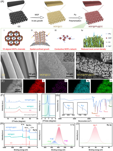
In the preparation of MgMOF@PPy@CC, an optimization method to prepare PPy without the use of aqueous solution was adapted to prevent the decomposition of MgMOF. After polymerization, the MgMOF@PPy@CC sample became black ultimately (Figure S6), indicating polymerization of the pyrrole monomer. MgMOF@PPy@CC showed a Brunauer–Emmett–Teller surface area and porous volume of ca. 222.21 m2 g−1 and 0.179 cm3 g−1, respectively, lower than those of MgMOF@CC (ca. 397.91 m2 g−1 and 0.354 cm3 g−1), due to the polymerization of PPy in the MgMOF cavity (Figure S7). However, the specific surface area of MgMOF@PPy@CC was still much higher than that of the CC material (ca. 16.92 m2 g−1, Figure S8), which could decrease the local current density and thus inhibit the detrimental growth of Mg dendrites.35, 36 The mass loadings of MgMOF and PPy were ∼19.50 wt% (3.78 mg cm−2) and 6.65 wt% (1.29 mg cm−2), respectively (Figure S10).
According to scanning electrode microscopy (SEM), MgMOF was evenly distributed on CC (Figures 2C and S11), while the untreated CC showed a smooth surface (Figure 2B). The morphology of MgMOF@PPy@CC was similar to that of MgMOF@CC (Figure 2D), confirming that PPy was mainly distributed in the MOF cavity (Figure 2D). The O, C, N, and Mg elements were distributed uniformly, confirmed from the elemental mapping analysis (energy-dispersive X-ray spectroscopy [EDS]) (Figure 2E). Owing to the intrinsic electric conductivity of PPy, MgMOF@PPy@CC showed improved electronic conductivity of 3.68 S cm−1 over MgMOF@CC (0.018 S cm−1), which is beneficial for the electrochemical application. The characteristic X-ray diffraction (XRD) peaks of MgMOF@PPy@CC were consistent with those of pristine MgMOF@CC, with a slight red shift of 0.25° (Figure 2F). The result indicated that the infiltration of PPy did not damage the topological framework of MgMOF. No spectral peak of PPy was observed due to its amorphous characteristic (Figure S12).
Moreover, the Fourier-transform infrared (FTIR) spectra of MgMOF@PPy@CC were found to be in the range between 400 and 4000 cm–1 (Figure 2G). Two peaks located at 580 and 486 cm−1 appeared because of the presence of Mg–O vibration.37 The feature peak appeared at 1213 cm−1, corresponding to C–H stretching vibration, and the peaks at 884 and 818 cm−1 were attributed to the C–H bending vibration of the benzene ring.37 The peak at 1575 cm−1 was associated with the C═O bond in the organic ligand of MgMOF and the C═C stretching vibration of the pyrrole ring.37, 38 Additionally, compared with the FTIR spectra of CC (Figure S8B) and MgMOF@CC (Figure S9), specific peaks at around 3529 and 1710 cm−1, attributed to N–H and C–N stretching from PPy, were observed, which further confirmed the successful decoration of PPy.39, 40 The comparison of solid-state ultraviolet–visible absorption spectra also confirmed the polymerization of PPy in the MgMOF@PPy@CC system (Figure S13). In short, MgMOF@PPy@CC has been elaborately designed and successfully prepared.
As shown in the X-ray photoelectron spectroscopy (XPS) spectra, Mg, O, N, and C elements were observed in MgMOF@PPy@CC, while the N element was absent in MgMOF@CC and CC materials, confirming the integration of PPy into the former (Figure 2H). Moreover, in addition to a major peak ascribed to the pyrrolic-NH moiety (399.8 eV), subpeaks related to C═N (398.5 eV), C–N+ (401.2 eV), and C═N+ (402.2 eV) were also observed in the N 1s spectrum (Figure 2I).41 As for the Mg 2p, the peak attributed to the Mg–O bond (binding energy at 50.2 eV) was examined in MgMOF@PPy@CC (Figure 2J).42 The contact angle was determined and MgMOF@PPy@CC showed a contact angle of 0° (Figure S14). The good wettability between the substrate and the electrolyte was conducive to improving the diffusion kinetics of Mg2+ ions, thus facilitating epitaxial electrodeposition of Mg atoms onto the MgMOF@PPy@CC substrate.43 Moreover, the N2 adsorption–desorption curve indicated that MgMOF@PPy@CC was endowed with a 3D porous structure (Figure S7), which was also confirmed by the SEM images of CC and schematic architectures of MgMOF and MgMOF@PPy (Figures S16–S18). The ingeniously designed structure enabled sufficient contact with the electrolyte and induced more active sites, thus enhancing the uniform deposition of Mg.
Furthermore, MgMOF@PPy still showed an adsorption energy of −2.52 eV towards Mg atoms, which was much higher than that of the bare CC substrate (−0.91 eV) and slightly lower than that of the MgMOF substrate (−2.73 eV) (Figure S19 and Table S2). The high adsorption energy endowed the MgMOF@PPy matrix with a strong magnesiophilic nature to reduce the nucleation barrier, thus promoting uniform Mg deposition.
2.3 Electrochemical properties
To evaluate the electrochemical performance, asymmetrical Mg//CC and Mg//MgMOF@PPy@CC cells were assembled. The nucleation overpotentials are shown in Figure 3A. Under a current density of 1.0 mA cm−2, the MgMOF@PPy@CC electrode showed a lower nucleation overpotential of 70 mV, while that of the CC electrode was 527.9 mV. When the current density was increased to 5 and 10 mA cm−2, the nucleation overpotentials of the MgMOF@PPy@CC electrode were 224 and 404 mV, while those of the CC electrode were 650 and 1106 mV, respectively (Figure 3B). The results confirmed the enhanced Mg nucleation kinetics facilitated by the MgMOF@PPy@CC nanoarray substrate. The Mg electrostripping/plating kinetics was also studied by the cyclic voltammetry (CV) curves. The onset reduction potentials for MgMOF@PPy@CC and CC electrodes were calculated to be −54 and −107 mV, respectively (Figure 3C). Compared with the CC electrode, the MgMOF@PPy@CC electrode showed higher current density both in the cathodic and anodic sweep processes. Moreover, the quicker charge-transfer kinetics was also confirmed by electrochemical impedance spectroscopy results (Figure S20). According to the Tafel curves, compared with the CC electrode, the MgMOF@PPy@CC electrode showed higher exchange current density, confirming the enhanced interfacial charge-transfer kinetics (Figure 3D).44 As shown in Figure 3E, under a current density of 8.0 mA cm–2, the MgMOF@PPy@CC//Mg cell could run stably for 2200 h, while the Mg//CC cell was only able to cycle stably for 48 h. This result experimentally confirmed the superior electrochemical reversibility of the well-designed MgMOF@PPy@CC electrode. The Coulombic efficiency (CE) is an important index to estimate the reversibility of Mg electroplating/stripping processes. The MgMOF@PPy@CC electrode showed constant high CE values for 1100 cycles (average CE values of 99.7%, Figure S21), with negligible fluctuation, further revealing its strong ability to accommodate high amounts of Mg electrodeposits. Conversely, the bare CC showed poor CE within only 24 cycles, because of nonuniform Mg dendrites. For the MgMOF@PPy@CC electrode, the 3D porous structure, endowed with vertically aligned MgMOF, could effectively reduce the local current density. Furthermore, MgMOF, characterized by its magnesiophilic nature and intricately spatially constrained frameworks, showed a seamless and uniform Mg nucleation process, thereby contributing to a highly efficient and reversible cycling performance.

More excitingly, the MgMOF@PPy@CC symmetric cell worked stably over 1500 h, with little fluctuation, at a current density of 5 mA cm−2 (Figure 3F). The voltage hysteresis was maintained at around 200 mV in the whole circulation procedure, confirming stable Mg electrodeposition/dissolution without degradation. However, the CC//CC cell showed an initial polarization voltage of ∼259 mV that gradually fluctuated to 500 mV, which failed only after 96 h. When the current density was increased to as high as 10 mA cm−2, the MgMOF@PPy@CC electrode could work for 1200 h (Figure 3G). Nevertheless, the CC electrode could operate just 23 plating/stripping cycles at such a high current density (Figure 3G). To date, compared with the reported studies, the MgMOF@PPy@CC electrode has shown the best Mg electroplating/stripping performance (Figure 3H).22, 27, 45-49 Moreover, the types of electrolytes are listed in Table S3, which significantly affected the deposition performance of Mg.50-52 At the same time, the plating and stripping rate performance was also tested at 5, 10, and 15 mA cm−2 (Figure 3I). The MgMOF@PPy@CC electrode showed lower overpotentials under all the current densities, while the CC symmetric cell showed larger overpotentials and failed to work at a current density of 15 mA cm−2, probably because of dendritic electrodeposits.27 The above results demonstrate that MgMOF@PPy@CC has enhanced electron/ion transfer kinetics, effectively curbing dendrite growth. This finding could be attributed to the synergistic interplay of spatial confinement effects and epitaxial electrodeposition mechanisms.
To study how MgMOF affects the Mg nucleation and growth process, the deposition morphology evolution of Mg electrodeposits on MgMOF@PPy@CC and the CC electrode was compared with different specific capacities. Uniform Mg electrodeposition was found on the surface of the MgMOF@PPy@CC substrate (Figure 4A–C), due to heteroepitaxial electrodeposition in a strain-free state facilitated by the regular interface electrostatic field as well as spatially confined growth of Mg electrodeposits. When the specific capacity was increased to 5 mAh cm−2, the electrodeposits also appeared to have a smooth surface (Figure 4B). Surprisingly, the Mg deposits showed a homogeneous and smooth layer on the MgMOF@PPy@CC surface, even when the capacity was as high as 10 mAh cm−2 (Figure 4C). Moreover, the deposited MgMOF@PPy@CC electrode could recover to the initial state with no extra Mg deposits left after stripping, confirming the excellent reversibility of Mg plating/stripping (Figure 4D). On the contrary, the deposited CC electrode could not completely return to the original state, with the random Mg aggregates covered on CC (Figure 4D), further confirming the poor affinity between Mg and the CC substrate. The results indicated that the MgMOF@PPy@CC electrode could effectively promote uniform Mg electrodeposition/dissolution while simultaneously increasing electrochemical kinetics.
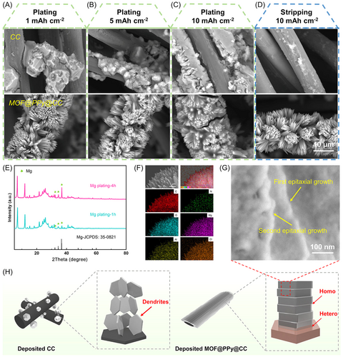
To study the epitaxial electrodeposition of Mg, ex situ experiments were performed. XRD patterns were also obtained after Mg electrodeposition for 1 and 4 h (Figure 4E). The characteristic peaks of Mg could be observed after Mg electrodeposition for 1 h, and the peaks strengthened after Mg deposition for 4 h. This result indicated that the MgMOF@PPy@CC substrate maintained its initial phase, confirming its structural stability. As shown in Figure 4F, the discharged MgMOF@PPy@CC was composed of Mg, C, O, N, Al, and Cl elements. The difference in elemental contents before and after Mg deposition showed that the elemental content of Mg increased after deposition, which further explained Mg deposition (Figure S23). After discharge to 30 min at 1 mA cm−2, a lamellar Mg nanosheet was formed hetero-epitaxially on the MgMOF@PPy@CC substrate (Figure 4G). As schematically shown in Figures 1A and 4H, the as-fabricated 3D MgMOF@PPy@CC substrate had excellent magnesiophilic characteristics, low crystalline lattice misfit with Mg, regular electrostatic field, and the space-confinement effect. The ingenious design effectively facilitated heteroepitaxial Mg electrodeposition, resulting in the formation of compact and uniformly distributed deposits. In contrast, the agglomerated Mg electrodeposits showed a random distribution on the CC matrix, potentially leading to short circuits and diminished battery performance.
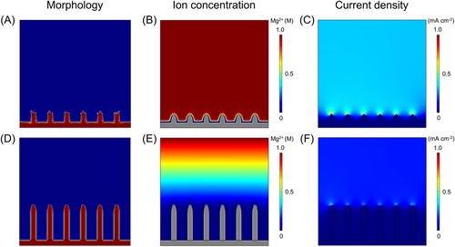
The Mg2+ ion distribution, current density, and deposition morphology during Mg electrodeposition onto MgMOF@PPy@CC and CC electrodes were studied using the phase-field method in COMSOL Multiphysics 6.1. Consistent with the morphology observed in the experiment, the model with vertically oriented MgMOF crystals was constructed on the CC electrode (Figure 5D), with bare CC as the control group (Figure 5A). The results showed that the concentration of Mg2+ ions was uniform within the 3D MgMOF@PPy@CC electrode, attributed to the decreased current density in the channel and the magnesiophilic nature of the substrate (Figure 5E).53 By comparison, increased polarization of the Mg2+ ion concentration was observed on bare CC (Figure 5B), with more Mg atoms depositing on the crystal tip and fewer Mg atoms depositing at the bottom, inducing nonuniform Mg dendrites (Figure 5A). Moreover, the current density was uniformly distributed around the 3D MgMOF@PPy@CC electrode (Figure 5F). In contrast, dendritic Mg deposited on bare CC, with higher distribution polarization of current density (Figure 5C). It can be concluded that the construction of the 3D porous MgMOF@PPy@CC electrode promoted homogenization of Mg2+ ion flux and decreased concentration polarization, effectively promoting uniform Mg deposition.
To study the potential of the MgMOF@PPy@CC electrode in practical applications, full cells, assembled with the Mo6S8 cathode, were examined. As shown in Figure 6A, the Mo6S8//MgMOF@PPy@CC battery showed higher current density as well as a smaller anodic/cathodic gap than the Mo6S8//Mg battery. This result confirmed that the MgMOF@PPy@CC electrode had quicker charge/ion transfer kinetics. The rate capabilities of Mo6S8//MgMOF@PPy@CC and Mo6S8//Mg batteries were investigated and the current densities ranged from 5 to 70 C, as shown in Figure 6B. The Mo6S8//MgMOF@PPy@CC battery showed higher specific capacity than the Mo6S8//Mg battery, due to the smaller charge-transfer resistance and the unique 3D-porous structure. Most significantly, the MgMOF@PPy@CC anode, coupled with the Mo6S8 cathode, could operate stably over 10,000 cycles at 70 C, showing an excellent capacity retention of 96.23% (Figure 6C). By comparison, the Mo6S8//Mg battery failed only after 800 cycles, which might have been caused by dendritic Mg deposition (Figure S24). All the results revealed that the MgMOF@PPy@CC anode showed improved cycling and rate performance at high current density compared with the pure Mg anode, due to inhibited Mg dendrite growth and homogeneous electrodeposition.
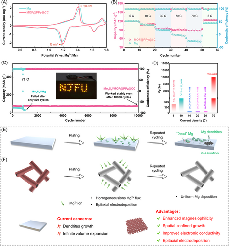
The conventional Mg anode was generally exposed to Mg dendrites and showed inevitable volume expansion during the electroplating–stripping cycling process (Figure 6E). In contrast, the MgMOF@PPy@CC electrode could serve as an excellent substrate for Mg electrodeposition/dissolution due to the synergistic effect of the interconnected CC, uniformly distributed MgMOF, and epitaxial electrocrystallization (Figure 6F). The MgMOF@PPy@CC electrode showed excellent electronic conductivity, which could ensure enhanced electrochemical kinetics and homogeneous Mg2+ ion flux. Moreover, due to the interconnected CC and large specific surface area of MgMOF, it could act as a favorable substrate to lower the surface current density and provide sufficient space for Mg electrodeposition. MgMOF, with ordered 1D nanochannels and the space-confinement effect, promoted preferential growth of Mg crystals in the successive channels. The chosen MgMOF substrate had a notably low lattice-misfit rate, enabling the feasibility of heteroepitaxial electrodeposition for Mg atoms.
3 CONCLUSIONS
In summary, the as-fabricated MgMOF@PPy@CC electrode successfully achieved epitaxial electrodeposition and spatially confined growth of Mg crystals. The exceptional compatibility between MgMOF and Mg, marked by a minimal lattice geometrical misfit of 0.93%, provided essential conditions for epitaxial electrodeposition. Detailed DFT calculations unveiled the substrate's highly magnesiophilic nature and a periodic electrostatic potential field that enabled efficient capture of Mg2+ ions and their reduction to enriched electron sites. The spatially confined framework of MgMOF promoted the preferential growth of Mg metal within successive nanochannels, skillfully preventing the formation of dendritic structures. Finite element simulations corroborated this phenomenon, demonstrating a uniform Mg2+ ion distribution, even current density, and consistent deposition morphology within the intricate 3D architecture of the MgMOF@PPy@CC electrode. Remarkably, the resultant MgMOF@PPy@CC electrode showed exceptional cycling stability, even under the demanding conditions of ultrahigh current density, outperforming previously reported benchmarks with a remarkable 1200-h stability at 10 mA cm−2. This achievement was attributed to the porous MgMOF framework and uniform Mg deposition driven by the epitaxial electrodeposition process. Most importantly, the assembled cell, with a MgMOF@PPy@CC anode and a Mo6S8 cathode, showed an unprecedented operational longevity of over 10,000 cycles, with an impressive capacity retention rate of 96.23%. This work not only offers a pioneering perspective on the rational design of epitaxial electrocrystallization propelled by the MOF matrix but also potentially provides an avenue for the advancement of next-generation battery technologies.
ACKNOWLEDGMENTS
This work was supported by the National Natural Science Foundation of China (Grant No. 31770608), the Jiangsu Specially-appointed Professorship Program (Sujiaoshi [2016]20), and the Postgraduate Research & Practice Innovation Program of Jiangsu Province (Grant No. KYCX22_1081).
CONFLICT OF INTEREST STATEMENT
The authors declare that there are no conflicts of interests.


