How to perform a sonographic morphological assessment of the fetus at 11–14 weeks of gestation
Abstract
Introduction
First-trimester ultrasound is widely accepted as part of standard care in many countries. With improvements in equipment, expertise and increasing number of technical studies describing imaging techniques, the detection rate for major fetal anomalies in the first trimester continues to rise and can be as high as 60% in high-risk populations.
Methods
We set out to create a systematic pictorial guide for trained ultrasound providers to describe the common anatomical structures that are identifiable in the first trimester with provided images. In addition to normal anatomical structures, a number of anomalies with high detection rates are listed.
Conclusion
A large proportion of the major fetal abnormalities can be detected in the first trimester. A systematic approach is essential to ensure that anomalies are equally likely to be detected for patients of any risk background.
Introduction
Routine first-trimester ultrasound has widely become accepted as standard care in pregnancy in most countries. With the introduction of non-invasive prenatal testing (NIPT) by analysis of cell-free fetal DNA (cffDNA) in maternal blood, and with increasing resolution of ultrasound imaging, the role of the first-trimester ultrasound has shifted beyond simply assessing viability, gestational age, fetal number and aneuploidy risk by nuchal translucency. Assessment of fetal anatomy has become increasingly more accurate, and a significant proportion of major fetal abnormalities can now be detected in the first trimester.1, 2
Overall detection rates of major fetal anomalies in the first trimester can be as high as 60%3 and are highest for abdominal wall, central nervous system, cardiac and skeletal anomalies.1, 4 Historically, these abnormalities were discovered on further detailed examination of the fetus with raised nuchal translucency; however, the first-trimester ultrasound is evolving into a screening opportunity for morphological anomalies and these findings are increasingly being discovered during initial assessment.5
Multiple guidelines exist listing anatomical structures for assessment such as the practice guidelines published by the International Society of Ultrasound in Obstetrics and Gynaecology (ISUOG).6 Additionally, many authors have previously described the assessment of specific anatomical structures in the first trimester; however, few have developed complete pictorial guides to anatomical imaging in the first trimester.
This article aims to assist trained sonographers in a systematic and universal approach to assessing fetal anatomy, to unify the current literature in a unique pictorial guide and to list common anomalies that providers should be mindful of in the first trimester.
Methods
This pictorial essay was compiled from images of first-trimester ultrasounds performed between 11 + 0 and 13 + 6 weeks of gestation using two different ultrasound machines: GE Voluson E10® and E6® (General Electric, Boston, MA, USA).
In addition to describing standard planes for the assessment of normal views of anatomical structures (Table 1),6 common fetal anomalies detectable in the first trimester are listed (Table 2).
| Head | Present |
| Cranial bones | |
| Midline falx | |
| Choroid-plexus-filled ventricles | |
| Neck | Neck normal appearance |
| Nuchal translucency thickness (if accepted after informed consent and trained/certified operator available) | |
| Face | Eyes with lens |
| Nasal bone | |
| Normal profile/mandible | |
| Intact lips | |
| Spine | Vertebrae (longitudinal and axial) |
| Intact overlying skin | |
| Chest | Symmetrical lung fields |
| No effusions or masses | |
| Heart | Cardiac regular activity |
| Four symmetrical chambers | |
| Abdomen | Stomach present in left upper quadrant |
| Bladder | |
| Kidneys | |
| Abdominal wall | Normal cord insertion |
| No umbilical defects | |
| Extremities | Four limbs each with three segments |
| Hands and feet with normal orientation | |
| Placenta | Size and texture |
| Cord | Three-vessel cord |
| Structure/Abnormality | Reported detection rate at 11–14 weeks (%) |
|---|---|
| Head | |
| Encephalocele | 100 |
| Acrania | 96.9–100 |
| Holoprosencephaly | 77.8–100 |
| Cerebellar hypoplasia | 50 |
| Hydrocephaly | 16 |
| Ventriculomegaly | 9.1–15 |
| Neck | |
| Cystic hygroma | 100 |
| Face | |
| Facial cleft | 13–24.3 |
| Spine | |
| Hemivertebrae | 66.7 |
| Sacrococcygeal teratoma | 50 |
| Open spina bifida | 25–36.8 |
| Thorax | |
| Diaphragmatic hernia | 0–50 |
| Heart | |
| Ectopia cordis | 100 |
| All congenital heart disease | 84, 97 with NT >2.5 mm |
| AVSD | 95 |
| HLHS, single ventricle | 100 |
| TOF | 43 |
| Great artery defects | 25 |
| Abdomen | |
| Megacystis | 88–100 |
| Duodenal atresia | 33 |
| Renal agenesis (bilateral) | 28.6 |
| Hydronephrosis | Bilateral 27.3, Unilateral 6 |
| Multicystic dysplasia | 14.3–33 |
| Abdominal wall | |
| Body stalk anomalies | 100 |
| Exomphalos | 100 |
| Gastroschisis | 85.7–100 |
| Cloacal extrophy | 100 |
| Limbs | |
| Club hand | 100 |
| Skeletal dysplasia | 50–86 |
| Absent hand/foot | 33–77.8 |
| Polydactyly | 60 |
| Short long bones | 0–50 |
| Talipes | Bilateral 14.3–25, Unilateral 3.8–6.5 |
| Achodroplasia | 25 |
| Genitalia | |
| Cloacal defect | 100 |
| Umbilical cord | |
| Single umbilical artery | 57.1 |
- AVSD, Atrioventricular septal defect; HLHS, Hypoplastic left heart syndrome; TOF, Tetralogy of Fallot.
Equipment
It is recommended that ultrasound equipment should satisfy the following list of capabilities:
- Real-time, greyscale, two-dimensional ultrasound
- Transabdominal (usually 3–10 MHz curvilinear) and transvaginal (3–12 MHz) transducers.1 Where image acquisition is difficult transabdominally, transvaginal ultrasound has been shown to significantly improve imaging quality for adequate completion of the first-trimester ultrasound7
- Adjustable acoustic power output controls with power display standards
- Freeze frame and zoom capabilities
- Electronic callipers
- Capacity to print and store images
- Regular maintenance and servicing.6
Scanning pre-sets
Ultrasound exposure should be limited in accordance with ALARA principles (As Low As Reasonably Achievable).8 Modern ultrasound machines will have a first trimester pre-set, which optimises images for this stage of pregnancy. B and M mode settings appear safe at all gestational ages9; however, the use of Doppler ultrasound should be limited wherever possible due to concerns related to increased temperatures generated.10
Viability
Fetal heart motion and rate should be documented to confirm viability.
Gestational age
Crown rump length (CRL)
CRL measurement is most accurate when the embryo or fetus is oriented to allow a horizontal measurement line at 90° to the ultrasound beam in a midsagittal section. For accurate assessment, the image of the fetus should be magnified to occupy most of the width of the ultrasound screen. The fetus should be in a neutral position with the head neither flexed nor extended. Inferior limbs should not be visible. There should be amniotic fluid visible between the fetal chin and chest. Linear callipers are applied to the greatest width between the crown and rump (Figure 1). This measurement can be acquired through abdominal or transvaginal ultrasound. Precision is essential, as the adequate dating of the pregnancy with early ultrasound is shown to reduce the rates induction of labour due to post-dates pregnancies and inaccurate measurements can lead to incorrect diagnosis of small or large for gestational age fetuses later in pregnancy.6, 11

Biparietal diameter (BPD) and head circumference (HC) plane
This plane can be used if the CRL is above 84 mm to accurately determine gestational age. HC is more accurate than BPD for determining gestational age.6 Measurement can be transabdominal or transvaginal. The measurement should be of the largest true symmetrical axial view of the fetal head without compression from the ultrasound probe. The falx should be orientated midline in the fetal cranium. Both anterior horns, low occipital lobes, cerebral ventricles, thalami and third ventricle should be visible in the correct plane. The cerebellum should not be included.6 The BPD measurement should be performed in the widest biparietal diameter with the callipers placed in the outer part of one parietal bone and in the inner part of the other parietal bone. The HC measurement can be taken with the placement of an ellipse following the outer part of the skull bones or by adding the occipitofrontal diameter (OFD) measurement to the previously measured BPD.
Anatomical survey
Head
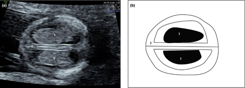
The fetal skull begins to ossify at 11 weeks of gestation and a symmetrically ossified skull is visible in axial and coronal planes. The lateral ventricles are prominent and filled with symmetrical echogenic choroid plexuses (“butterfly sign,” Figure 2). Symmetrical hemispheres are clearly delineated by the interhemispheric fissure and falx. Ensuring that the skull is complete and intact is key in ruling out major defects like anencephaly and encephalocele, and visualisation of the integrity of the falx in its whole extension excludes alobar holoprosencephaly.
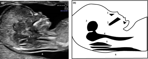
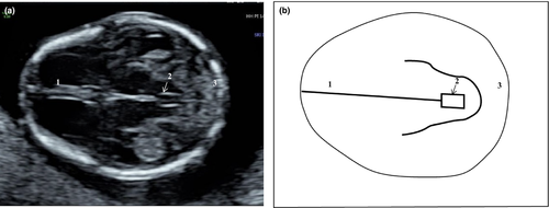
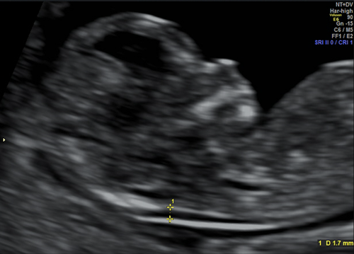
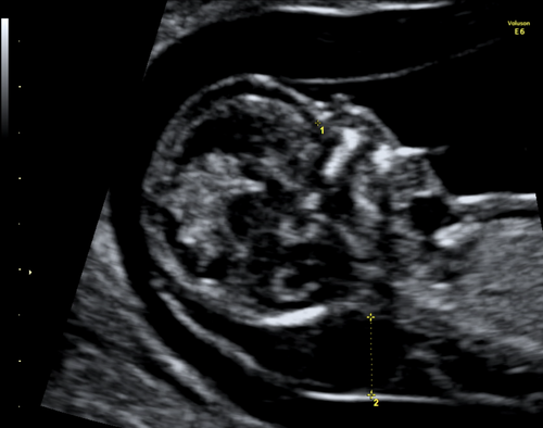
The posterior fossa structures may not be visible at this stage, but a reduced or absent posterior intracranial translucency (IT) can be suggestive of open neural tube defects. The IT should ideally be visualised in the midsagittal view (the same plane where nuchal translucency is measured, Figure 3).12 In the axial plane, visualisation of the aqueduct of Sylvius (Figure 4) and its distance to the occipital bone can also be of help in the detection of open spina bifida, in which case the examination of the spine with transvaginal ultrasound may increase the detection rate.6
Neck
Nuchal translucency (NT) remains an important measurement to screen for chromosomal abnormalities and other anomalies, in particular congenital heart defects.13 NT is most accurate when the neck and trunk are aligned. Ideally, the vertebral column and the fetus should be aligned in a midsagittal plane, confirmed by visible nasal bone and tip of the nose, hard palate and diencephalon. The maxilla should not be seen, and the magnification should be such that only the fetal head and upper thorax appear in the screen, occupying at least 75% of it. The neck should neither be flexed or extended. Amniotic fluid should be visible between the fetal neck and uterine wall (Figures 3, 5 and 6). Callipers are placed inside the hyperechoic edges, vertically, in the widest portion of the NT.14, 15 A transverse suboccipitobregmatic section of the fetal head may be useful in detecting increased nuchal translucency. Although some studies suggest that septations, known as cystic hygroma, increase the risk of fetal chromosomal abnormalities, the NT measurement itself is the main independent marker for abnormalities.15
Face
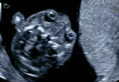
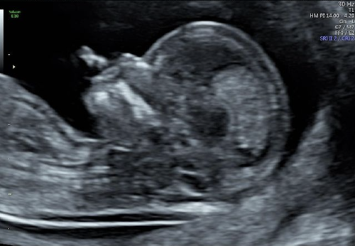
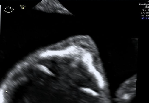
The presence of two orbits and the eye lenses can be evaluated in the first trimester (Figure 7). The nose, nasal bone, mandible and mouth and lips can also be assessed in profile. Profile view can be achieved by aligning the orbits in an axial plane and rotating the ultrasound probe 90°. The nasal bone should be visualised clearly with the fetal profile occupying the majority of the acquired image, and should appear thicker and more echogenic than the overlying skin (Figures 3 and 8). The fetal face profile and the normal appearance of the chin can be seen in midsagittal plane with visualisation of the tip of the nose. Ideally, the profile should be at 45° from the probe.6 The palate can be seen in both the sagittal view as a hyperechoic rectangle (Figures 3 and 8) or axial views (Figure 9), and major facial clefts can be suspected already in the first trimester, triggering an early morphology assessment at 16–18 weeks of gestation.16 A coronal view of the anterior part of the face including the nasal bones and the palate is known as the retro-nasal triangle and can also be used in assessing the integrity of the palate (Figure 10). Although detection of major cleft lips is possible, assessment of the fetal lips in the first trimester is limited and can be misleading.
Absent nasal bone—additional markers increase the accuracy of first-trimester combined screening for fetal aneuploidies but should not be used for risk calculation if cell-free fetal DNA test has already been performed.17 In these cases, a new risk should not be generated by ultrasound markers or maternal biochemistry, except in cases of cffDNA test failure. The accuracy of cffDNA test relies on the proportion of fetal DNA in the maternal circulation,18 known as fetal fraction, and when below certain thresholds, the test manufacturers will not issue a test result.17
Spine
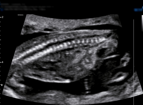
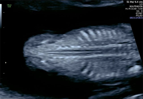
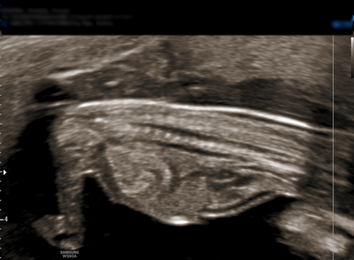
Longitudinal (sagittal and coronal—Figures 11 and 12) and axial views of the spine are important to demonstrate alignment and integrity of the overlying skin (Figures 11 and 13).6 As mentioned above, when assessing the fetal head, an abnormal intracranial translucency should increase suspicion of neural tube defects.12 Transvaginal ultrasound also improves image resolution for more accurate assessment of the fetal spine.7
Thorax
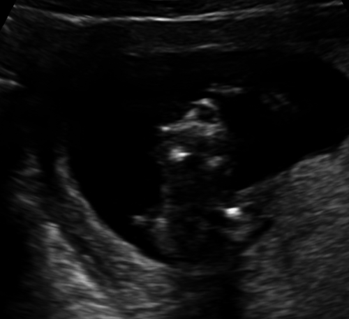
The chest can be evaluated for a continuous diaphragm and homogenous echotexture of the lungs. The position of the stomach and fetal liver assists in demonstrating an intact fetal diaphragm and correct situs of the heart and abdominal organs. It is important not only to confirm that both heart and stomach are on the same side, but that they are both on the left side of the fetal body (Figure 14).6
Heart
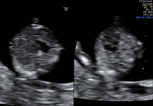
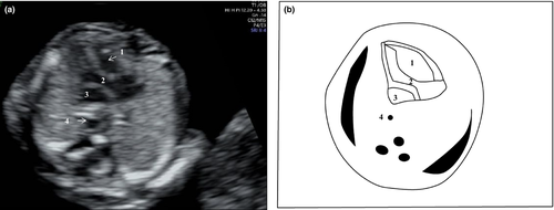
Situs of the fetal heart should be confirmed in the left hemithorax. Cardiac anatomical assessment of the four-chamber view with symmetrical ventricles is now considered achievable at this gestation19 (Figures 15 and 16). Acquire a transverse plane of the fetal thorax with the ossifying fetal ribs lengthened as a guide to ensure the probe is aligned correctly.6 The heart axis should be of 45° with an imaginary line perpendicular to the vertebra, and an abnormal cardiac axis can be associated with cardiac defects. The anatomy of the heart and the offsetting of the atrioventricular valves can be assessed in a single cephalad sweep (Video S1).
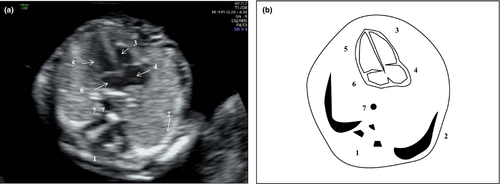
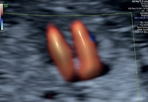
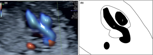
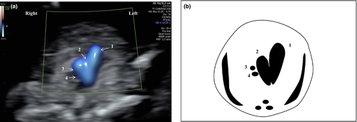
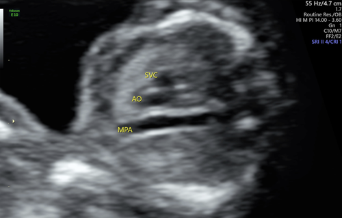
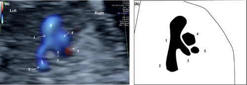
In addition, the left (Figures 17 and 18) and the right (Figures 19, 20 and 21) ventricular outflow tracts and their crossover can be visualised with colour Doppler to demonstrate that both pulmonary artery, ductus arteriosus and aortic arch have forward blood flow (“V sign,” Figure 19). A three-vessel view can also be achieved by sweeping the probe cephalad from the four-chamber view (Figure 20). This is useful when transposition of the great arteries, Tetralogy of Fallot and early presentation of severe coarctation of the aorta are suspected.
Abdominal wall
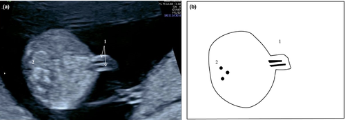
Umbilical cord insertion should be noted during routine first-trimester ultrasound (Figure 22). A physiological hernia may be visible until 11 weeks of gestation but should not be present with CRL measurement above 54 mm.6
Abdomen
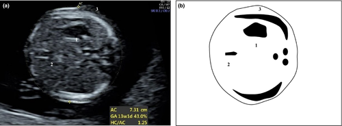
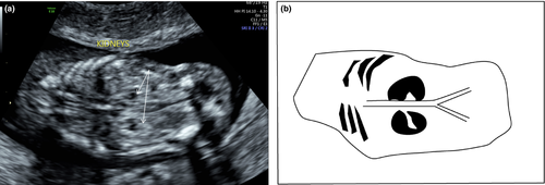
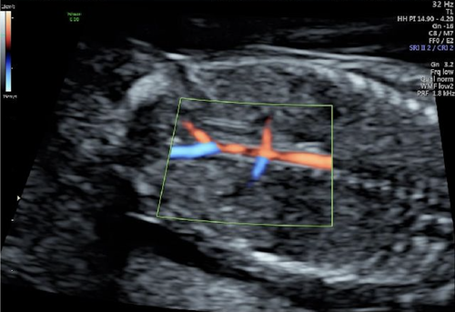
Ultrasound imaging of the abdomen should include identification of the stomach on the left side of the fetus (Figures 14 and 23), and the fetal bladder midline in the lower abdomen can be identified in both longitudinal and transverse sections of the fetal pelvis (Figures 24 and 25). In case of prominent bladder, a persistent measurement of more than 6 mm indicates the presence of megacystis. This finding is associated with chromosomal abnormalities, such as trisomy 18, or suggests lower urinary tract obstruction, such as posterior urethral valves.2 Fetal kidneys are visible as paraspinal hyperechoic structures in the coronal view (Figure 26),6 and in cases of suspected renal agenesis, the use of colour Doppler to demonstrate the presence or the absence of the renal arteries may be helpful (Figure 27).

Umbilical cord
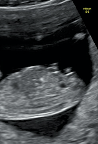
The number of cord vessels can be determined by highlighting the paravesical region with colour Doppler (Figure 25).10
Genitalia
Fetal external genitalia is best evaluated in the midsagittal plane (Figure 24); however, it may be difficult to discern in the first trimester. Currently, no morphological assessment of the genitalia can be performed in the first trimester and identification of the fetal gender can be misleading.6
Limbs
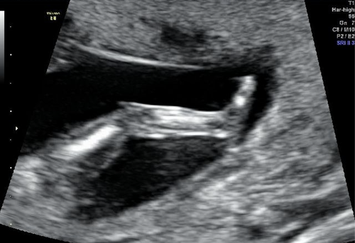
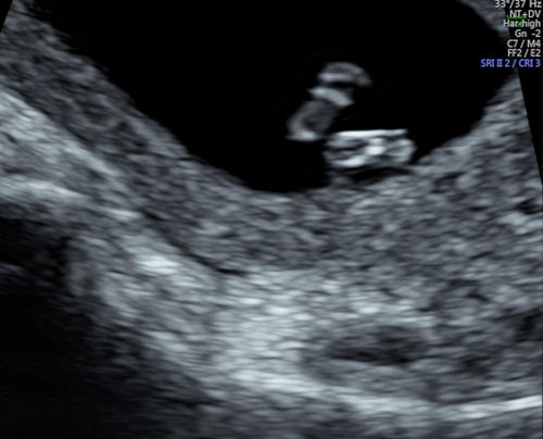
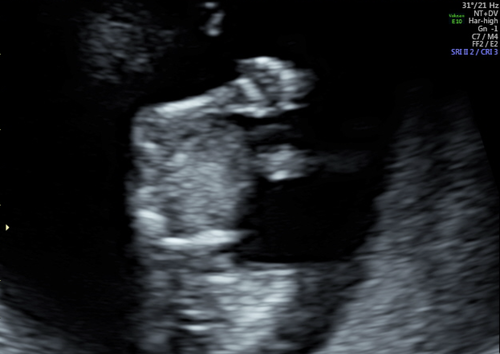
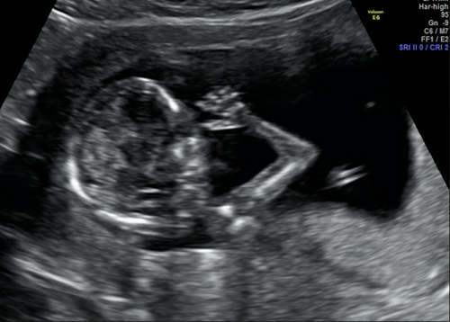
It is crucial to ensure that both lower limbs (Figures 28 and 29) and both upper limbs (Figure 30 and 31) are present. The bony segments of the upper and lower limbs and extremities should be visualised as well as the terminal phalanges of the hands. Caution is recommended when there is suspected talipes or polydactyly, as these conditions are difficult to diagnose in the first trimester in the first trimester.6
Conclusion
The first-trimester ultrasound has developed into an opportunity to screen for a number of significant fetal anomalies associated with fetal and neonatal morbidity and mortality. Although the sensitivity of Down syndrome screening by ultrasound techniques has been outperformed by fetal cell-free DNA technologies, first-trimester ultrasound remains pivotal in the early detection of fetal structural anomalies. Detection rates for certain lethal fetal anomalies can be as high as 100%, which affords healthcare providers the opportunity to identify and counsel patients earlier in the pregnancy which has significant implications with regard to management options.
A systematic approach is essential in ensuring accuracy and reproducibility between ultrasound providers. The above is a useful approach to assessing anatomical structures that are visible at this early gestation.
Conflict of interest
The authors report no conflict of interests.
Author contributions
EAS: Design of the study, writing of the manuscript, collection of ultrasound images, review and approval of the final version of the manuscript. DLR: Conception and design of the study, writing of the manuscript, collection of ultrasound images, review and approval of the final version of the manuscript. MR: Collection of ultrasound images, review and approval of the final version of the manuscript. SG: Collection of ultrasound images, review and approval of the final version of the manuscript. MM: Collection of ultrasound images, review and approval of the final version of the manuscript. JK: Collection of ultrasound images, drawing of the schematic figures, review and approval of the final version of the manuscript. SM: Design of the study, collection of ultrasound images, review and approval of the final version of the manuscript. MT: Collection of ultrasound images, review and approval of the final version of the manuscript. FSC: Conception and design of the study, collection of ultrasound images, review and approval of the final version of the manuscript.


