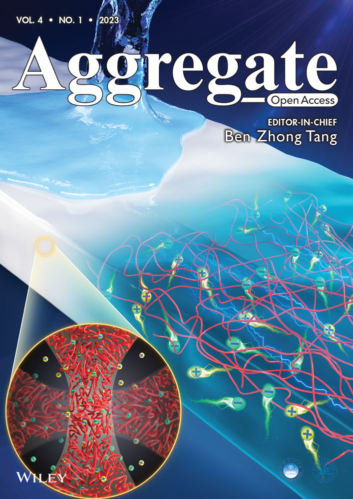
Fabrication of luminescent patterns using aggregation-induced emission molecules by an electrolytic micelle disruption approach
Abstract
Herein, we report an electrochemical strategy that could control the location of aggregation-induced emission (AIE) molecules on patterned electrodes in a precise and facile way, producing photoluminescent and electrochemiluminescent patterns with a variety of colors. A micelle composed of electroactive surfactants was broken during the electrooxidation process, in which AIE molecules inside these micelles were released on patterned electrodes. These patterned electrodes were pretreated by not only metal, but also multifarious conducting polymers (CPs). An in-depth investigation clarified a correlation between the variety of CPs used as electrodes and the oxidation rate of the electroactive surfactant due to different catalytic performances of CPs. Furthermore, combined with wireless and gradient features of bipolar electrochemistry, a gradient luminescent pattern was easily achieved. The current studies suggest more abundant luminescent patterns using AIE luminophores can be developed by such an electrochemical method, in both of graphical shapes and emitting colors.
1 INTRODUCTION
Luminescent materials are broadly used for fundamental studies and practical applications, such as chemical sensing,[1-3] light emitting device,[4-6] and especially bio-imaging.[7] Classic studies of organic luminescence have generally been conducted in a solution state, because these organic luminophores performed very negative light-emitting behaviors at a high concentration or a solid state.[8-11] The above-described phenomenon is well known as “aggregation-caused quenching” (ACQ).[12] Since the ACQ effect is harmful to some practical applications, many researchers have made great efforts to tackle the problem and break the intrinsic limitation. In 2001, Tang's group firstly proposed a concept of “aggregation-induced emission” (AIE) in the study of 1-methyl-1,2,3,4,5-pentaphenylsilole, which revealed the possibility of chromophoric organics giving a strong light-emission in the solid state.[13-15] To date, a rich series of AIE luminogens (AIEgens) have been developed. These organic emissive materials are normally used as thin solid films in devices, in which aggregation is inherently accompanied with the film formation. In particular cases, patterning these AIEgens to display and transfer signal events is much more interesting, such as the visualization of latent fingerprints.[16] The fabrication of colorful luminescent patterns could be achieved by several strategies. The most adopted approach is using the AIEgens as an ink, then coating could be achieved by drawing or spraying the ink solution on a substrate, affording a targeted luminescent pattern.[17] But the controllability and the precision are inadequate. On the other hand, electrochemical approach is a more straightforward way to construct such luminescent films by electrochemical polymerization of AIE monomers on the pretreated electrode surface,[18] which is possible to obtain AIEgens-based polymeric luminescent patterns. However, a considerable drawback of electropolymerization process is its strict requirements for the polymerizable monomer of AIE molecules.[19, 20] Therefore, a precisely controlled and generally applicable way to draw luminescent patterns is worth exploring.
Saji's group has reported a unique electrochemical approach to fabricate thin films, known as the electrolytic micelle disruption method.[21, 22] In the system, organic compounds were incorporated in a micelle consisted of electroactive surfactants with a ferrocenyl group. Organic compounds were released from the micelle and deposited on the electrode surface to form a film when the ferrocenyl group in the surfactants was electrochemically oxidized. In our previous study, three kinds of AIEgens including tetraphenylethene (TPE),[23] tris(4-nitrophenyl) phenylethene (TPE3N),[24] and hexaphenylsilole (HPS)[25] have been successfully introduced to α-(11-ferrocenylundecyl)-ω-hydroxypoly(ethylene glycol) (FPEG) micelles, producing AIE films using the electrolytic micelle disruption method.[26] In fact, the approach can be generalized to a large variety of AIE molecules, as long as they can be solubilized or dispersed by electroactive surfactants.
Here, we contrived a strategy that patterned electrodes were designed, and subsequent functionalization of electrodes was followed using the electrolytic micelle disruption method to deposit colorful luminescent patterns derived from TPE, TPE3N, HPS and benzothiadiazole–triphenylamine (BTD-TPA). AIEgens of BTD-TPA having dual photo-responsive and electro-responsive emission features were firstly employed for the micelle disruption method using FPEG micelles. In this work, the insulating glass surface was decorated using gold and conducting polymers (CPs) to form customized patterns. Employing an electrolytic micelle disruption process, AIEgens precisely deposited on the gold/CP-decorated patterns, endowing the pristine conductive surface with a luminescent property. Taking advantages of the distinguished catalytic performances of different CPs, the release rate of AIEgens from micelles on various CP surfaces can be further regulated. Furthermore, integrated with a bipolar electrochemical system, a gradient luminescent pattern was directly accessed.
2 RESULTS AND DISCUSSION
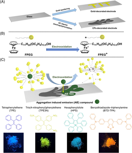
The general concept of the work is described in Figure 1. Patterned electrode surfaces were drawn using gold or the CPs. A gold decorated electrode was fabricated by the gold sputtering, while a CP-modified one was made by the electropolymerization of aromatic monomers (Figure 1A, Figure S2). Then, electroactive FPEG experienced an electrochemical oxidation on the patterned electrode (Figure 1B). The structure of an FPEG micelle was broken following the oxidation process, resulting in the release of incorporated AIEgens. These free AIEgens were only located on the electroactive area where electrochemical process occurred, endowing the original region with a perceptible luminescence under ultraviolet (UV) light. A large variety of AIEgens were introduced to such a system, including TPE, TPE3N, HPS, and BTD-TPA (Figure 1C).
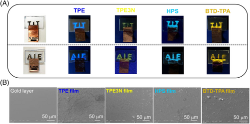
Firstly, “AIE/TIT” electrodes were adopted for the electrolysis with a three-electrode system using micellar solutions. Here, the applied potential (E) was 0.5 V versus SCE, while the electricity passed (Q) was 0.5 C for “TIT” pattern and 1 C for “AIE” pattern in all cases. As a result, AIEgens were released from micelles and deposited on “AIE/TIT” areas, producing colorful patterns endowing with bright blue, yellow, sky-blue, and orange light under UV irradiation (λ = 365 nm), which corresponded to emission colors of various AIEgens (Figure 2A). Such a functionalization process could be extended infinitely to more complicated cases, combined with advanced and delicate patterning techniques aiming to individual demands. On the basis of scanning electron microscopy (SEM) images in Figure 2B, the AIEgen layers formed uniformly and smoothly. The TPE case was flatter without grains and coating blister, compared with the TPE3N, HPS, and BTD-TPA cases. During the film formation, the debris with apparent rectangular edges appeared firstly, then small molecules inserted into the spaces between debris as electrolysis continued.[26] Therefore, the method could give the high quality of luminescent patterns. In a first set of proof-of-principle experiments, we investigated the fabrication of luminescent patterns on metal-modified surfaces to validate the general concept.
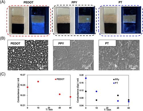
CPs as popular electrode materials have attracted much attention owing to their tunable morphological features, high charge densities, and low costs.[27] The discussed approach was then extended to CPs. In this part, we firstly prepared three kinds of CP films, that is, poly(3,4-ethylenedioxythiophene) (PEDOT), polypyrrole (PPY), and polythiophene (PT), acting as electrodes with a consistent surface area (10 mm × 10 mm). Interestingly, after 1 h electrolysis (E = 0.2 V vs. SCE) using the micellar solution incorporating TPE, the largest amount of TPE deposited on the PEDOT surface, having the brightest blue emission under UV irradiation (λ = 365 nm), while a weak blue emission on PPY and PT surfaces (Figure 3A). The experimental results were supposed to be electrocatalytic performances of CPs.[28-30] In fact, the electrocatalytic activity of CPs was affected by specific surface areas[31] and conductivities.[32] To better understand it, surface morphologies and electric properties of PEDOT, PPY, and PT films were systematically studied. The surface of the PEDOT film was the roughest with a plenty of grains, while the resultant PPY and PT films had relatively smoother surfaces (Figure 3B). A rougher specific surface area of PEDOT film provided more exposed active sites for enhancing its catalytic activity. On the other hand, in situ conductance measurements were carried out using Pt interdigitated microelectrode (IDME) during the electrolysis in micellar solutions. The experimental results demonstrated that the conductance of all CP films generally decreased during the electrolysis (E = 0.2 V vs. SCE), which was caused by the deposition of the TPE films on the CP film surfaces. And the conductance of PEDOT film was significantly higher than that of PPY and PT films (Figure 3C). High conductivity of PEDOT film was beneficial to the charge transfer at the interface between the electrolyte and the electrode, accelerating the electrooxidation of the FPEG surfactant. In conclusion, the larger specific surface area and the higher conductivity of the PEDOT film made it a superior performance on the oxidation of FPEG, which released more TPE molecules to give a brighter luminescent film.
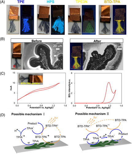
Associated with an originally well-developed CP-patterning technique from our group, PEDOT patterns were drawn on a glass substrate surface by an AC bipolar electropolymerization (Figure S2).[33] The fabricated PEDOT pattern was used as an anode for a constant voltage electrolysis (E = 0.2 V vs. SCE, Q = 0.1 C) using micellar solutions with AIEgens. As a consequence, clear and gorgeous AIE patterns under UV irradiation (λ = 365 nm) were achieved, perfectly reflecting the microscopic branching structure of PEDOT patterns (Figure 4A). SEM image of the branching PEDOT film before and after electrolysis verified that the backbone of the PEDOT branching was kept intact in an appreciable manner (Figure 4B). Therefore, the proposed method to fabricate luminescent patterns in electrochemical manners was successfully extended to CPs fields. Besides, BTD-TPA compound with an electron-withdrawing BTD core and two electron-donating TPA wings could generate the aggregation-induced electrochemiluminescence (AIECL),[34, 35] which was also observed in the fabricated BTD-TPA pattern. When the BTD-TPA pattern was used as the working electrode for cyclic voltammetry (CV) measurements, ECL profiles were obtained simultaneously in the presence of tri-n-propylamine (TPrA) as a coreactant. At the initial period, the oxidation current should come from the doping of PEDOT. Then, the current significantly increased again at about 0.9 V, in which ECL signal started. The secondary improvement of current was resulted from the oxidation of TPrA, while the oxidation of BTD-TPA is possible with the increasing applied potential, giving ECL emission. And the intensity of ECL emission reached the maximum at 1.2 V (Figure 4C). For the AIECL phenomenon on PEDOT surface, two possible mechanisms are proposed here.[34] For a direct pathway, both the BTD-TPA luminogen and the coreactant, TPrA, are directly oxidized on the surface of PEDOT to generate BTD-TPA•+ and TPrA•+. TPrA•+ undergoes deprotonation to generate an intermediate TPrA•, which acts as a reducing agent for BTD-TPA•+ to produce an excited state (BTD-TPA*). BTD-TPA* returns to the ground state through radiative decay, accompanied by light emission. For another revisited pathway, only the coreactant is oxidized, and the resulting radical TPrA• reacts with the luminogen to generate light emission (Figure 4D). Compared with other three patterns, the produced BTD-TPA pattern demonstrated not only a photoluminescent property, but also an ECL feature.
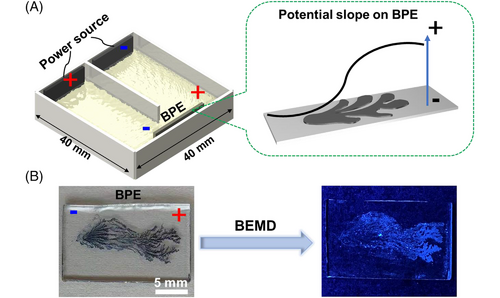
To enrich the family of luminescent patterns, we finally intended to make a gradient pattern using a bipolar electrochemical micelle disruption approach.[26] A general U-shaped bipolar electrochemical setup includes a pair of driving electrodes connected to a power supply, and a bipolar electrode (BPE) embedded in an electrolytic solution.[36] A sigmoidal potential distributes on the wireless BPE surface, which offers an in situ generated controllable template to conduct gradient micelle disruptions (Figure 5A).[37-41] When a PEDOT branching pattern was used as the BPE for electrolysis, the disruption rate of FPEG micelles carrying TPE was gradient along the surface of PEDOT pattern, following the local potential distribution. The brightest position appeared at the anodic terminal of the BPE, then luminescent intensity decreased toward the cathode of the BPE, giving a gradient AIE luminescent pattern in a facile way (Figure 5B).
3 CONCLUSION
In summary, we constructed a facile and general electrochemical strategy to endow conductive patterns with colorful luminescent properties. Both specially shaped metal electrodes and CP electrodes were precisely decorated by a wide range of AIEgens after experiencing a micelle disruption process. More inspiringly, benefiting from the superior catalytic performance of PEDOT film on the oxidation of FPEG surfactants, the amount of AIE molecules released on the PEDOT surface was significantly improved than that on other CP surfaces. In addition, the gradient TPE pattern can also be achieved, combining the proposed method and the wireless bipolar electrochemical system.
The presented straightforward approach can be generalized to more complex patterns with the combination of other advanced pretreatment techniques, such as 3D printing of PEDOT patterns on the soft hydrogel.[42] This makes it a promising technique to construct AIEgens patterns, not only in the field of display, but even for more sophisticated concepts. Certainly, applicative AIEgens in the micelles could be greatly extended from small molecules to polymers, moving a step forward to more plentiful luminescent patterns.
4 EXPERIMENTAL SECTION
4.1 Materials
Tri-n-propylamine (TPrA), tetrabutylammonium perchlorate (Bu4NClO4), tetrabutylammonium tetrafluoroborate (Bu4NBF4), tetrabutylammonium hexafluorophosphate (Bu4NPF6), lithium bromide (LiBr), TPE, HPS, organic solvents, 3,4-ethylenedioxythiophene (EDOT), thiophene, pyrrole, indium tin oxide (ITO) conductive glass, glass, and copper tape were obtained from commercial sources. All chemicals and reagents were used without further purification. TPE3N and FPEG were synthesized according to our previous report.[20] Benzothiadiazole–triphenylamine (BTD-TPA) was synthesized according to the literature (Figure S1).[28, 29] Platinum (Pt) IDME was purchased from BAS company. ITO glass and glass were washed using methanol, deionized water, and acetone in sequence, then dried for use. Electrolytic solutions were deaerated by an intensive argon bubbling before use.
4.2 Instruments
Nuclear magnetic resonance spectroscopy was measured on a Bruker biospin AVANCE III 400A. Constant potential electrolysis was carried out with a HOKUTO DENKO HABF-501A. An Autolab PGSTAT101 in combination with the NOVA software was used for ECL experiments. Conductance measurement was realized by an ALS/DY 2325 bi-potentiostat. An EC1000SA AC/DC power source from NF Corporation was employed for a bipolar electrolysis. A UV lamp (SLUV-4, AS ONE) acted as a UV light source. Gold (Au) thin layer was spattered using an Eiko IB-3 ion coater. SEM observation measurement was conducted using a JEOL JSM 6610.
4.3 Preparation of micellar solutions
An aqueous solution containing 2.0 mM FPEG, 0.1 M LiBr, and 10 mM AIEgens (TPE, TPE3N, HPS, or BTD-TPA) was sonicated for 2 h and stirred for 5 days to prepare a micellar solution. The supernatant was then separated for the electrolysis.
4.4 Preparation of CP films on ITO surfaces
A three-electrode system was employed to prepare PEDOT, PPY, and PT films, using an ITO (10 mm × 20 mm) as a working electrode, a Pt plate (20 mm × 20 mm) as a counter electrode, an SCE as a reference electrode. An MeCN solution with 10 mM EDOT and 0.1 M Bu4NClO4 was electrolyzed by applying a potential of 1.6 V (vs. SCE) on the working electrode to obtain a PEDOT film. An MeCN solution with 10 mM pyrrole and 0.1 M Bu4NClO4 was electrolyzed at 1.8 V versus SCE to give a PPY film. An MeCN solution with 400 mM thiophene and 0.1 M Bu4NBF4 was electrolyzed at 2.0 V versus SCE to prepare a PT film. The electropolymerized area was (10 mm × 10 mm), and passed electric charge was kept at 0.5 C in all cases. These CP films were carefully washed in MeCN and dried for use.
4.5 Conductance measurement using an IDME
PEDOT, PPY, and PT films were prepared on a Pt IDME (65 pairs of Pt bands on glass substrate, 10/5 μm, electrode/gap) by electropolymerization. The electropolymerization conditions were consistent with the preparation of CP films on ITO surfaces. For the Pt IDME, the electropolymerized area was (2.5 mm × 2.0 mm), and passed electric charge was 25 mC. Then, Pt IDME covered with CP films was used as a working electrode in micellar solutions for electrolysis (E = 0.2 V vs. SCE). During the process, the conductance of them was measured in aqueous solution with 0.1 M LiBr at various periods. The conductance measurements were carried out by using the CP-coated Pt IDME as a working electrode, a Pt plate (20 mm × 20 mm) as a counter electrode, and an SCE as a reference electrode. For the conductance measurement, potential difference between pairs of Pt bands (Vbias) was maintained at 0.01 V, and scan rate was 50 mV/s with a range from 0.15 V to 0.25 V.
4.6 ECL measurement
An electrolytic cell containing a mixed solution of MeCN/H2O (v/v = 7:1) with 0.1 M Bu4NPF6 as a supporting electrolyte and 20 mM TPrA as a coreactant was used. The ECL cell was placed in front of the photomultiplier tube. Both ECL profiles versus potentials and the corresponding cyclic voltammograms (CV) were recorded simultaneously. Potentials were scanned between 0 V and 1.5 V at a scan rate of 100 mV/s, using the BTD-TPA pattern as a working electrode, an Ag/AgCl electrode in 3 M NaCl solution as a reference electrode, and a Pt plate as a counter electrode (20 mm × 20 mm).
ACKNOWLEDGMENTS
This work was supported by a Kakenhi Grant-in-Aid (JP20H02796) from the Japan Society for the Promotion of Science (JSPS) and PRESTO (No. JPMJPR18T3) of the Japan Science and Technology Agency (JST). YZ acknowledges fellowship support from the China Scholarship Council (201806280051) for study at the Tokyo Institute of Technology and acknowledges the support from the Kato Foundation for Promotion of Science (KS-3102).
CONFLICT OF INTEREST
The authors declare that the research was conducted in the absence of any commercial or financial relationships that could be construed as a potential conflict of interest.
Open Research
DATA AVAILABILITY STATEMENT
The data that support the findings of this study are available from the corresponding author upon reasonable request.


