Structural performance of split orthogonal beam joints in continuous beam-type circular concrete-filled steel tubular beam-to-column connections
Abstract
A continuous beam-type connection has been proposed as a new type of concrete-filled steel tubular beam-to-column connection without a diaphragm exhibits good seismic performance. However, in a 2-way configuration, the performance of the connection in a direction orthogonal to the continuous beam may be suboptimal due to beam splitting. In this study, a new detail of a split orthogonal beam joint was proposed and 4 specimens were constructed and tested under quasi-static conditions. All the specimens attained the full-plastic flexural strength for the beams and exhibited a stable inelastic behavior. The specimen in which the depth of the orthogonal continuous beam was 100 mm greater than that of the split beam exhibited good inelastic cyclic behavior, whereas two other specimens with a split beam exhibited slipping and pinching. Minor fractures were observed in the tube wall; however, the strength and stiffness did not deteriorate significantly, though a slight pinched hysteresis was observed. In addition, a finite element analysis was conducted. The split beam was largely rotationally constrained by the bearing pressure of the concrete above and/or below the beam flange. If the split beam's flange was sufficiently inserted into the connection panel, the stiffness and strength were ensured.
1 Introduction
Beam-to-column connections using diaphragm plates are a common type of moment connection in concrete-filled steel tubular (CFST) structures. The diaphragm plates transfer the sectional forces from the beam end to the column steel tube. Design procedures for connections using diaphragm plates have been established. However, the design formulae for diaphragms in CFST structures are complicated because of the necessity of perforations for concrete filling.1
A continuous beam-type connection has been proposed as a new type of CFST beam-to-column connection without a diaphragm.2, 3 In this connection, the I-section beam passes through the column steel tube. The connection can be constructed using only fillet welding, which simplifies the construction procedure. This connection can ensure that the steel beam easily develops a plastic moment capacity and it simplifies the design procedure for CFST beam-to-column connections. However, in a 2-way configuration, the beam in this connection in the orthogonal direction to the continuous beam cannot pass through the column because of the existence of the continuous beam. The beam must be split and jointed using fillet welding on only one side of the column steel tube. The beam that passes through the column is defined as the “continuous-beam,” while the beam that is orthogonal to the continuous beam is defined as the “split-beam.”
The conventional method of fixing the end of a split-beam involves a simple method of bolt-joining an I-section steel beam web and a single plate welded to a column steel tube. Instead of a single plate, an angle or tee section welded/bolted to the column tube can be used as well.4 Such a connection, called a “single-plate shear connection,” simplifies the construction procedure. However, it is difficult to ensure the moment capacity of the I-section beam. This type of connection is generally used with bracing to sufficiently resist lateral forces.
Fujinaga and Clifton proposed a new detail for the split-beam in the orthogonal direction of a square CFST beam-to-column connection. A specimen of the proposed detail showed sufficient strength and stability owing to the lever action but exhibited slightly pinched hysteresis at small rotation angles.5 The depths of the continuous and split beams were identical to those reported in Ref. [5]. However, the depth of the continuous beam may differ from that of the split-beam.
In this paper, for the connection between a circular CFST column and an I-section steel beam, simpler split-beam joint details are proposed for cases in which the depth of the orthogonal continuous beam is greater than that of a split-beam. Four CFST beam-to-column connection specimens were fabricated and tested quasi-statically. The basic joint performance and stress transfer mechanism of the split-beam joint orthogonal to the continuous beam were discussed and examined. In addition, a finite element analysis was also conducted to investigate the stress transfer mechanism around the connection panel.
2 Sub-Assemblage Test for Beam-to-Column Connections
2.1 Specimens
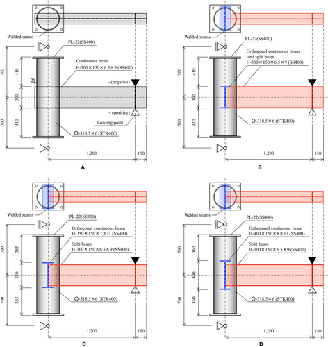
Figure 1 shows the specimen dimensions. T-shaped configurations were designed to replicate the circular CFST beam-to-column connections containing a continuous-beam (see Table 1). The specimen required cutting an I-section beam slot in the column steel tube by gas cutting with a tolerance of 2 mm in order to pass the beam through the column. After inserting the I-section beam through the slot, the I-section beam was fillet-welded around its perimeter to the outer faces of the column. For the split-beam specimen, which was orthogonal to the continuous-beam, a short continuous-beam was arranged as a transverse beam. The concrete was cast using a conventional pouring method.
| Specimens | Column | Continuous-beam or split-beam | Orthogonal continuous beam | Concrete compressive strength (MPa) |
|---|---|---|---|---|
| T-21 | 318.5 × 6 | H-300 × 150 × 6.5 × 9 | – | 31.7 |
| O-21-300 | 318.5 × 6 | H-300 × 150 × 6.5 × 9 | H-300 × 150 × 6.5 × 9 | 31.8 |
| O-21-350 | 318.5 × 6 | H-300 × 150 × 6.5 × 9 | H-350 × 150 × 7 × 11 | 30.6 |
| O-21-400 | 318.5 × 6 | H-300 × 150 × 6.5 × 9 | H-400 × 150 × 8 × 13 | 33.1 |
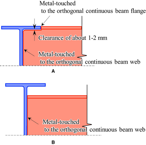
Specimen T-21 was a continuous beam-type specimen, whereas Specimens O-21-300, O-21-350, and O-21-400 were split-beam-type specimens, which was equipped with the continuous-beam with depths of 300, 350, and 400 mm, respectively. For Specimens O-21-350 and O-21-400, the split-beam orthogonal to the transverse continuous-beam was metal-touched to the web of the continuous-beam (see Figure 2). For Specimen O-21-350, the gap between the split-beam flange and the continuous beam flange is 14 mm, which is smaller than the maximum aggregate size of the concrete. For Specimen O-21-300, the part of the flange of the split-beam that overlapped with the continuous-beam was cut, and the web of the inserted split-beam was metal-touched to the web of the transverse continuous-beam, with a clearance of approximately 1–2 mm between the flange of the transverse beam and the web of the inserted split-beam.5
Standard tensile and compressive tests were conducted on steel and concrete to ascertain the mechanical properties of the materials used. Table 2 presents the measured results.
| Specimens | Yield strength (MPa) | Yield strain | Elastic modulus (GPa) | Ultimate strength (MPa) | Elongation (%) | |
|---|---|---|---|---|---|---|
| Column tube | 384 | 0.00189 | 203 | 486 | 30.1 | |
| H-300 × 150 × 6.5 × 9 | Flange | 335 | 0.00183 | 183 | 480 | 25.5 |
| H-300 × 150 × 6.5 × 9 | Web | 404 | 0.00219 | 185 | 513 | 23.6 |
| H-350 × 150 × 7 × 11 | Flange | 320 | 0.00174 | 184 | 462 | 25.5 |
| H-400 × 150 × 8 × 13 | Flange | 320 | 0.00180 | 178 | 471 | 25.7 |
2.2 Loading method
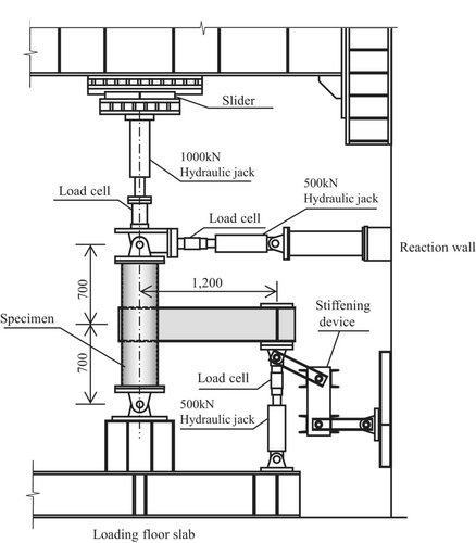
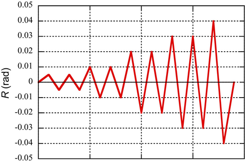
Figure 3 shows the loading apparatus used in this study. The column top end of the specimen was supported by a hinge and roller, whereas the bottom end was supported by a hinge. A shear force was applied using a hydraulic jack positioned at the beam end. Stiffening devices were installed at the beam end to restrict the displacement in the out-of-plane direction. The loading was controlled by the rotational angle, with targeted rotation angles of 0.005, 0.01, 0.02, 0.03, and 0.04 rad (see Figure 4). Two cycles were applied for each targeted rotation angle of R = 0.005, 0.01, 0.02, and 0.03 rad, while only 1 cycle was applied for R = 0.04 rad. The second cycle was used to assess whether strength and/or stiffness deteriorated compared to the first cycle. In contrast, only 1 cycle was applied for extremely large deformation R = 0.04 rad. The rotational angle R was calculated using the vertical displacement of the beam end and the distance between the loading point and the column center (1200 mm). An axial load equivalent to 10% of the squash load was applied to the CFST column of all the specimens, assuming conditions typical of mid-rise to low-rise buildings. The squash load is defined as the sum of the steel tube and concrete core strengths.
3 Test Results
3.1 Relationship between the shear force and rotation angle
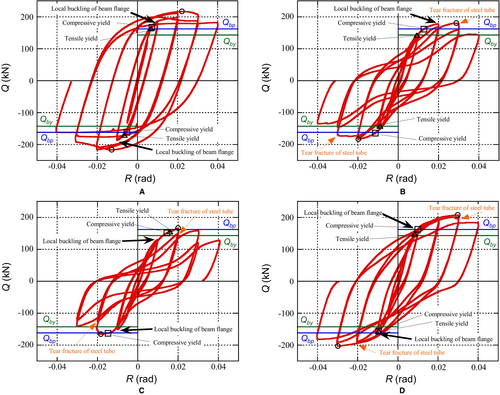
Specimen T-21 of the continuous beam type exhibited a stable hysteresis with a high energy dissipation capacity. Specimen O-21-350 exhibited a slipping behavior with a low energy dissipation. It reached the full-plastic flexural capacity at R = 0.02 rad; however, the energy absorption at large deformation range was poor. Specimen O-21-400 exhibited an inelastic behavior similar to Specimen T-21 and significantly improved behavior compared with Specimen O-21-350. Specimen O-21-300, with its details proposed in Ref. [5], showed a slightly improved behavior. It reached the full-plastic capacity but exhibited a pinched hysteresis behavior at large deformation range. This can be attributed to the tearing of the steel tube wall in the vertical direction immediately next to the split-beam flange as the beam was pulled out.
3.2 Strength comparison
Table 3 presents a comparison between the experimental results and the values predicted from the calculations. The calculated values of the yield and ultimate strengths were derived using the flexural yield moment My and full-plastic moment Mp. The experimental yield strength was represented by the force at which the strain gauge, which was attached 75 mm from the outer edge of the steel tube, reached the yield strain. For the continuous-beam-type specimen, the yield strength was predicted to be 10% higher, whereas the yield strength was accurately predicted for the split-beam-type specimens.
| Specimens | eQy (kN) | Mby (kNm) | Qby (kN) | eQy/Qby | eQu (kN) | Mbp (kNm) | Qbp (kN) | eQu/Qbp | Mcu (kNm) | Qcu (kN) |
|---|---|---|---|---|---|---|---|---|---|---|
| T-21 | 162 | 149 | 143 | 1.133 | 216 | 169 | 163 | 1.325 | 304 | 645 |
| O-21-300 | 142 | 149 | 143 | 0.993 | 180 | 169 | 162 | 1.111 | 304 | 645 |
| O-21-350 | 151 | 149 | 143 | 1.056 | 165 | 168 | 162 | 1.019 | 302 | 642 |
| O-21-400 | 147 | 149 | 143 | 1.028 | 204 | 169 | 162 | 1.259 | 306 | 649 |
The experimental maximum strengths of all the specimens exceeded the calculated ultimate value. For the continuous-beam-type specimen, the maximum experimental value exceeded the calculated value by 33%. In the case of split-beam-type specimens, the maximum strengths of Specimens O-21-400, O-21-350, and O-21-300 were 1.26, 1.02, and 1.11 times the calculated values, respectively.
3.3 Failure mechanism
For Specimen T-21 of the continuous beam type, the fillet weld between the continuous I-section beam and the outer faces of the column tube was completely intact until the test was completed. In Specimens O-21-300, O-21-350, and O-21-400 of the split-beam type, the fillet weld between the continuous I-section beam and the outer faces of the column tube fractured, causing a tear in the steel tube wall (see Figure 6). The tear fracture of the steel tube initiated at the edge of the flange at approximately R = 0.03 rad. As the tear fracture propagated, the continuous I-section beam was pulled out of the column tube. The fillet weld above or below the split I-section beam flanges developed a crack in the middle of each flange, that propagated toward each edge of the flange. While the fracture propagated over the entire weld length at R = −0.04 rad in Specimen O-21-300 and at R = −0.03 rad in Specimen O-21-350, and no sudden strength deterioration was observed. In Specimen O-21-400, the fillet weld on the outer side did not fracture completely. The stiffness deterioration resulted in a slipping behavior with a low energy dissipation. Specimen O-21-400 showed a slower progress of the fracture on the tube wall and the crack at the fillet weld on the outer side of the beam flanges, compared with the other two specimens, resulting in a small stiffness deterioration and significantly improved behavior. In addition, sufficient local buckling was also observed in the split I-section beam flanges.
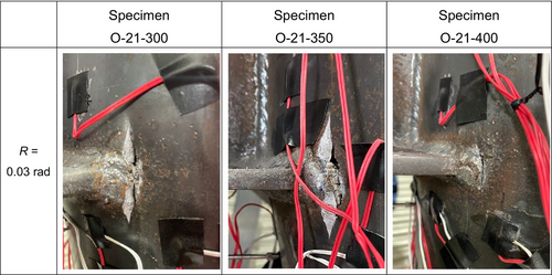
Generally, a frame with a split-beam-type connection is designed with bracing. Therefore, no significant deformation is expected.
3.4 Stress distribution of the steel tube above and below the beam
Figure 7 shows the stress distributions above and below the split I-section beam on the steel tube surface at the first cycle of positive loading R = 0.005 rad. Assuming a plane stress state, the axial and circumferential stresses were calculated using the strain values measured using 2-axis strain gauges attached to the steel tube surface 25 mm above and below the beam flanges (see Figure 8). The red line represents data on the bending-tension side surface below the beam, whereas the blue line represents data on the bending-compression side surface above the beam.
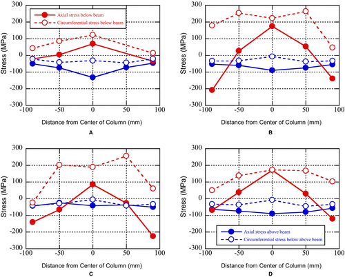
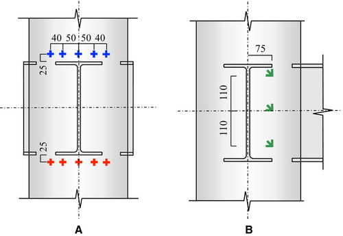
On the bending-tension side, the steel tube wall below the split I-section beam effectively transferred the tensile force from the beam flange in both the axial and circumferential directions. On the bending-compression side, the filled concrete directly resisted the compressive force from the beam flange, resulting in a low stress on the steel tube wall above the split I-section beam. On comparing the stresses below the I-section beam on the bending-tension side, we found that the stresses in the split-beam-type specimens O-21-300, O-21-350, and O-21-400 were higher than those in the continuous-beam-type specimen T-21. The greater stress transfer from the beam to the column can be attributed to two factors: the absence of fillet welding on the opposite side of the column tube and the small insertion depth of the split-beam. This corresponds to the experimentally observed phenomena, such as cracks and/or fractures in the fillet weld and the tearing of the steel tube wall. In addition, the circumferential stresses on the bending-tension side were relatively high, and the circular steel tube contributed to the transmission of the tensile forces from the beam flange.
3.5 Principal stress on the steel tube around the connection panel
Figure 9 shows the principal stresses on the steel tube surface around the connection panel at the first cycle of positive loading R = 0.005, 0.01, and 0.02 rad for the split-beam-type specimens O-21-300, O-21-350, and O-21-400. The principal stresses were calculated using the strain values measured by rosette strain gauges attached to the steel tube surface positioned 75 mm from the center of the continuous-beam web (see Figure 8). The red outward arrows and blue inward arrows indicate the tensile and compressive principal stresses, respectively.
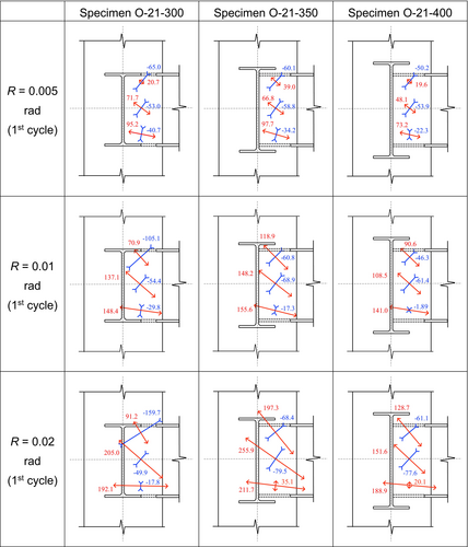
On the bending-tension side, the maximum principal stresses were approximately horizontal and the values of the tensile principal stresses were significant. This result suggests that the tensile force from the flange of the split-beam was effectively transferred as the circumferential stress. On the center and bending-compression sides, the maximum principal stresses were inclined diagonally toward the split I-section beam flange on the bending-tension side. It can be inferred that the steel tube effectively transferred the tensile force from the split-beam flange even at distant locations in the connection panel. The maximum principal stress under tension was the lowest in Specimen O-21-400 among the three specimens.
For the split-beam-type specimens O-21-350 and O-21-400, the minimum principal stresses under compression were lower on the bending-compression side than at the center of the connection panel. However, for Specimen O-21-300, the minimum principal stresses were highest on the bending-compression side and lower at other locations. It is inferred that the filled concrete in the connection panel can resist the compressive force from the split-beam flange on the bending-compression side. Therefore, the steel tubes in the split-beam-type specimens O-21-350 and O-21-400 did not significantly contribute to the compressive resistance.
4 Stress Transfer Mechanism Around the Connection Panel
4.1 Analytical modeling
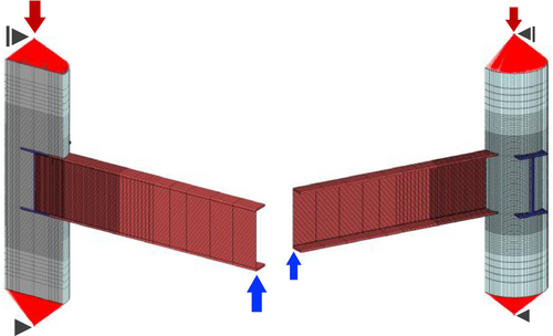
The nonlinear finite element analysis program MSC.MARC2022.36 was used for the modeling in this study. Figure 10 shows the finite element meshing of the CFST beam-to-column connection. The steel tube, the I-section beam, and the filled concrete were modeled using eight-node hexahedral or six-node wedge isoparametric solid elements. The friction coefficient between the steel and concrete in a composite structure is often 0.6.7, 8 However, in cases, such as partially filled CFST columns and shear connections in composite structures subjected to push-out tests, lower coefficients are more appropriate for evaluating the experimental values.9, 10 Komuro et al. and Guezouli et al. have conducted parametric studies using several friction coefficients as parameters; a value of approximately 0.3 provided a good predictions.11, 12 In our study, the friction coefficient between the steel and concrete was set to 0.25, as recommended by Ellobody and Young13 and Hassanein and Kharoob.14 The friction coefficient between the steels in the split-beam-type specimens was set to 0.35 and was used for the contact between the metal-touched continuous and split beams. The fillet weld between the column steel tube and the steel beam was modeled using the GLUE option, as the elements' shapes near the fillet weld deform due to node sharing.
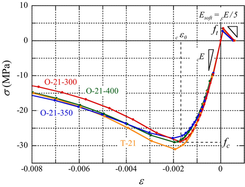
For the steel material model, the stress-strain relationship was assumed to be perfectly elastic-plastic. The constitutive law for the plastic region is based on the von Mises yield criterion. Figure 11 shows the uniaxial stress-strain relationship for the filled concrete model. The stress-strain curve was drawn using data obtained from the cylinder compression test until the peak was reached. The modified Ahmad model was used to define the post-peak stress-strain relationship.15 The Young's modulus cE was derived from the unloading curve of the stress-strain relationship up to a stress of 1/3 of the compressive strength fc, and the tension-softening modulus Esoft was 20% of the Young's modulus cE. The tensile strength ft was based on the splitting tensile strength of the cylinder. The CRACK DATA option was used to consider the tension softening and crushing. The constitutive law for the plastic region was based on the Mohr–Coulomb's failure criterion with an internal friction angle (φ) of 30° and α value of 0.16.
4.2 Analytical results
The shear force and rotational angle behaviors derived from the finite element analysis were compared with the experimental envelope curves during positive loading, as shown in Figure 12. Analytical behaviors for the fully fixed beam are also shown as ideal joint behaviors. The positive loading applied to the analytical model were monotonic, whereas those applied to the experimental specimens were cyclic.
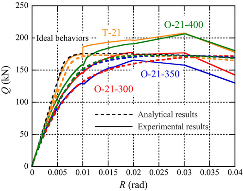
The analytical behaviors corresponded well to the experimental behaviors, especially up to R = 0.005 rad. In the FE analysis, little difference was observed between the Specimens O-21-350 and O-21-400. The difference in the behavior observed in the experiments may have been due to the incomplete filling of the concrete. For Specimens O-21-350 and O-21-400, the dominant factors in the stress transfer were the bearing pressure and the friction of the concrete around the split-beam flange. Sufficient stiffness and strength cannot be ensured if the concrete filling in the specimen is incomplete because of the presence of bleeding water and the smaller space for concrete filling. It is considered that in the case of Specimen O-21-400, which has a greater difference in the beam depth than O-21-350, a risk of the incomplete filling of concrete in the experiment tends to be small.
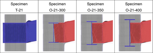
Figure 13 shows the von Mises stress distributions in the column steel tube and beam at R = 0.005 and 0.02 rad. Figure 14 shows the minimum principal stress distributions of the filled concrete at R = 0.005 and 0.02 rad. Figure 15 shows the deformation state in the joint panel at R = 0.04 rad, with the deformation scaled up by 500%.
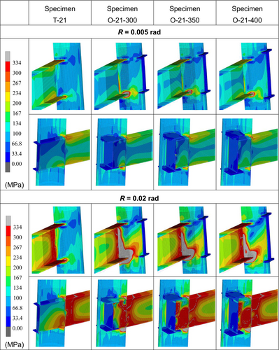
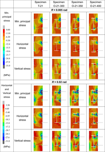
In all the specimens, the stresses at the split-beam end reached a sufficient yield stress, forming a plastic hinge. The split-beam transmitted the stresses to the center of the connection panel and the equivalent stresses were relatively high even within the steel tube. The beam transmitted a horizontal compressive stress to the concrete above and below the upper flange of the split-beam. The split-beam flange transferred the compressive stress to the concrete on the opposite side of the continuous-beam web. In addition, the concrete above and below the upper flange and below the lower flanges of the split-beam resisted the compressive force with a sufficient bearing pressure. The column steel tube transmitted the tensile force from the split-beam flange and stress concentrations were observed immediately next to the beam flange. The stress concentration location coincided with the location at which a crack was observed in the column steel tube during the test. With the increase in the rotational angle, a larger area contributed to stress transfer. The stress transfer in the steel tube was more effective on the bending-tension side than on the bending-compression side.
In the case of the continuous beam-type specimen T-21, the beam transmitted a stress on the bending-tension side to the concrete on the opposite side of the column. Stress concentrations were observed immediately adjacent to the beam flange in the column steel tube on the bending-tension side. However, even as the rotational angle increased, the plastic regions showed little expansion compared to those in the split-beam specimens.
The analytical results for Specimens O-21-350 and O-21-400 demonstrated extremely similar behaviors. The stress transfer by the concrete between the flanges of the continuous-beam and the split-beam was effective at small rotational angles. The concrete formed a compression strut that resisted the pulling out of the split-beam, and the concrete above and below the upper flange of the split-beam strongly constrained the rotation of the flange.
In the case of the split-beam-type specimen O-21-300, the top part of the split-beam web inserted between the flanges of the continuous-beam transmitted compressive stresses to the concrete on the opposite side of the continuous-beam web, in addition to the flange of the split-beam on the bending-compression side. Although the concrete above and below the upper flange of the split-beam constrained the rotation of the flange, the flange of the split-beam overlapping with the continuous-beam flange has been cut. Consequently, the web of the split-beam was constrained more weakly and the compression strut of concrete was not formed, resulting in a significant pull out of the split-beam flange. The column steel tube transmitted the tensile force from the split-beam flange across a broader area on the bending-tension side, compared to other split-beam-type specimens.
At the end of the split-beam inside the joint panel, the center of the rigid body rotation was around the compression flange near the center of the joint panel in Specimens O-21-350 and O-21-400; however, it was the compression flange near the column steel tube wall in Specimen O-21-300 and the degree of rigid body rotation was the highest with a significant pull out of the split-beam. This indicates that the absence of the split-beam flange in the connection panel caused the split-beam web to slip downward on the bending-compression side and the degree of fixation at the edge of Specimen O-21-300 was lower than that in the other two specimens. A deterioration in the stiffness is considered to have occurred at a small rotational angle.
5 Conclusions
- The experimental maximum strengths exceeded the calculated ultimate value and no sudden strength deterioration was observed in any of the specimens. Specimens O-21-300 and O-21-350 exhibited a slipping behavior with a low energy dissipation, whereas Specimen O-21-400 exhibited a stable hysteresis with a high energy dissipation capacity, similar to Specimen T-21.
- For Specimen T-21, the fillet weld between the continuous I-section beam and the outer faces of the column tube was completely intact. However, in the split-beam-type specimens, the fillet weld fractured, causing a tear in the steel tube wall at approximately R = 0.03 rad. The tearing of the steel tube was the smallest in Specimen O-21-400 among the three specimens.
- On the bending-compression side, the filled concrete directly transmitted the compressive force, whereas the steel-tube wall effectively transferred the tensile force from the beam flange on the bending-tension side. The circular steel tube contributed to the transmission of the tensile forces from the beam flange.
- Even at distant locations in the connection panel, the steel tube effectively transferred the tensile force from the split-beam flange and the maximum principal stresses were particularly significant on the bending-tension side. For Specimen O-21-300, the area of the flange inserted into the steel tube was smaller than that in the other two specimens. Therefore, the steel tube had a greater contribution to the compressive resistance.
- In Specimens O-21-350 and O-21-400, the split-beam flange was largely rotationally constrained by the bearing pressure of the concrete above and/or below the flange of the split-beam. In Specimen O-21-300, the pull out of the split-beam was the most significant among the split-beam-type specimens, primarily due to the cutting of the flange tip.
Acknowledgments
This research was funded by the Japan Society for the Promotion of Science (JSPS) Grant-in-Aid for Scientific Research (C) [grant numbers: 23K04120 and 20K04771].
Disclosure
The authors have no conflict of interest to declare.
Open Research
Data Availability Statement
Data that supporting the findings of this study can be made available from the corresponding author upon reasonable request.


