Design of Triple-Band Slotted Planar Antenna for WLAN/WiMAX and 5G Applications
Abstract
This paper presents a new small, low-profile planar triple-band microstrip antenna for WLAN/WiMAX and 5G applications. Nowadays, various wireless services are being integrated into a single device, so these devices require multiband resonant antennas to maintain their compact and portable size. Therefore, the aim of current research was to combine WLAN WiMAX and 5G communication standards together into a single wireless device by designing an antenna that can stimulate triple-band operation. The proposed antenna consists of circular-shaped rectangular slotted radiator encircled by a rectangular ring and a defected ground plane. The designed antenna has a compact size of 20 × 32 mm2 (0.16λ0 × 0.256λ0). The optimum dimensions were obtained using parametric studies of the key parameters of the antenna. The proposed antenna offers three different bands—I 2.3–2.70, II 3.2–3.92, and III 5.1–5.9 GHz, which clearly covers the entire WLAN (2.4/5.2/5.8 GHz), WiMAX (2.5/3.5/5.5), and 5G bands. Finally, a proposed antenna was built and studied experimentally to verify the design concept as well as validate the simulation results. The good agreement of the simulation results with the measured results proved that the antenna can simultaneously operate on WLAN (2.4/5.2/5.8 GHz), WiMAX (2.5/3.5/5.5 GHz), and 5G frequency bands. This antenna is a suitable candidate for a device that can be used for these three services simultaneously.
1. Introduction
Wireless local area networks (WLANs) and worldwide interoperability for microwave access (WiMAX) systems typically use planar antennas. The spectrum designated by the Federal Communications Commission (FCC) focuses on 2.4, 5.2, and 5.8 GHz for WLAN and 2.5, 3.5, and 5.5 GHz for WiMAX. The field of mobile and wireless communications is growing rapidly to cover many technological areas. Worldwide interoperability (WiMAX) technology for WLANs and microwave access is the fastest growing area in modern wireless communications. It provides users with the agility to move around in a wider coverage area for mobility and still stay connected to the network. It provides a lot of freedom and flexibility. For the home user, wireless devices have become popular due to ease of installation and freedom of location. Antenna is a very important component in wireless devices. Therefore, the need for efficient and high-performance antennas is ever increasing. Compact size, light weight, low cost, wide bandwidth, and the ability to resonate at multiple frequencies are generally desirable properties of antennas that every technology requires.
In [1], the performance of the upper band is improved by using parasitic patches and a director, while a modified U-shaped reflector is used to excite new resonances and to improve front-to-back of the lower band. The new resonant frequency in the antenna is excited using a capacitively coupled feeding structure and is combined with shorting pins and parasitic patches to increase the operating bandwidth of the antenna in [2]. In [3], triple-band operation and good impedance matching is achieved by carve-insert two inverted U-shaped slots of different sizes on the radiating patch and ground plane to simultaneously implement WLAN/WiMAX communication standard in a single device. In [4], high gain antenna for WLAN and WiMAX applications are designed using complimentary stubs on a single dielectric medium and fed with microstrip slot whereas a unidirectional radiation pattern is obtained by using a reflective ground plane. A resonant frequency and polarization reconfigurable antenna on a flexible polyethylene terephthalate (PET) substrate for WLAN and WiMAX devices is proposed and distribution of surface current is controlled by PIN-diode in [5]. In [6], a coplanar waveguide fed bow tie–shaped slot antenna carved by two slotted right angle triangles is proposed for WLAN/WiMAX applications. In [7], two F-shaped slotted rectangular patches are proposed to excite triple-band operation and gap-coupled circular-shaped stubs with a rectangular ground plane for impedance matching. The agility of the pattern in four directions is achieved by using four PIN-controlled tapered stubs and circular discs for WiMAX and WLAN devices [8] and in [9] space and polarization diversity is achieved by rotating the four multiband antenna elements around a circle to form a MIMO structure. In [10], multiple frequency operation for 2G/3G/4G/5G and WLAN/WiMAX wireless devices is commanded and generated using integrated parasitic patches with shorting pins, coupled feeding strips and planar folded dipoles. The antenna is proposed for GPS (L1-L5), PCS, IMT-2000, Bluetooth, WLAN, WiMAX, UWB, and X-band applications using a subsectional tapered feed line to resonate at the low frequency band [11]. In [12], a two-element array configuration of microstrip-fed slotted antenna is used for WLAN/WiMAX application and U-shaped slot is used for wideband multiple-input–multiple-output antenna [13]. In [14], an E-shaped coupled resonator and an L-shaped slot resonator are used to excite triple-band operation in ACS-fed bevelled monopole antenna for WiMAX operation. A triple-band antenna using rectangular complimentary ring resonator at the ground plane and an inverted T-shaped slotted radiator was proposed for WLAN/WiMAX applications in [15]. In [16], a meander line structure over a low-cost FR4 substrate with partial ground plane as a defected ground structure is proposed for multiband operation. A quad-band antenna made of two L-slots and a slit at the radiator is proposed in [17] for WiMAX/WLAN/GSM applications. In [18], asymmetrically CPW-fed SRR antenna made of a meander line, square-shaped split ring, and CPW ground plane is presented to radiate at dual-band resonance for WLAN and WiMAX applications. In [19], a beveling rectangular patch, a Pi-shape slot element, and an inverted-L slot element are used to excite triple-band resonance at WLAN and WiMAX applications. In [20], a square-shaped split ring resonator is used for size miniaturization and inward stub with rectangular type slotted partial ground plane for multiband operation. In [21], an inverted L-shaped slotted radiator beneath defected ground structure is proposed to incorporate WLAN and WiMAX communication standards in a single device. A triple-band hexagonal ring-shaped radiator is proposed for WLAN/WiMAX and 5G applications [22]. As the above literature review confirms that several antennas have been presented for various applications, there is a need to design an antenna that has compact size and multiband operation and is easy to manufacture. Moreover, comparison with the antennas reported in the literature listed in Table 1 clearly shows that the proposed antenna is compact in size and covers the entire WLAN/WiMAX and 5G bands.
| Ref. no. | Size (mm × mm) | Frequency band (GHz) |
|---|---|---|
| [3] | 10 × 26 × 1.6 | 2–2.52, 3.4–3.6, 5–6 |
| [4] | 96 × 73 × 1.5 | 2.45–3.5, 5.2–5.77 |
| [5] | 59 × 31 × 1.5 | 2.27–2.5, 3.5–3.77 |
| [9] | 76 × 76 × 1.5 | 2.4–2.5, 3.4–3.7, 5.1–5.9 |
| [10] | 31 × 11 × 1.6 | 2.3–2.7, 3.3–3.8, 4.9–5.85 |
| Proposed antenna | 20 × 32 × 1.6 | 2.3–2.7, 3.2–3.92, 5.1–5.9 |
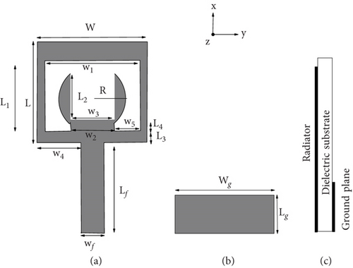
In this article, a small, low-profile planar triple-band microstrip antenna for WLAN/WiMAX and 5G applications is proposed. The aim of current research was to combine WLAN WiMAX and 5G communication standards together into a single wireless device by designing an antenna that can stimulate triple-band operation. The proposed antenna consists of circular-shaped rectangular slotted radiator encircled by a rectangular ring and a defected ground plane. The proposed antenna consists of circular-shaped rectangular slotted radiator encircled by a rectangular ring and a defected ground plane. The designed antenna has a compact size of 20 × 32 mm2 (0.16λ0 × 0.256λ0). The optimum dimensions were obtained using parametric studies of the key parameters of the antenna and enlisted in Table 2. The proposed antenna offers three different bands—I 2.3–2.70, II 3.2–3.92, and III 5.1–5.9 GHz, which clearly covers the entire WLAN (2.4/5.2/5.8 GHz), WiMAX (2.5/3.5/5.5), and 5G bands. The antenna design will be discussed in the following section, followed by results and discussion in the next section.
| Parameters | Unit (mm) | Parameters | Unit (mm) |
|---|---|---|---|
| L | 17.0 | W | 16.8 |
| L1 | 14.4 | w1 | 12.8 |
| L2 | 9.8 | w2 | 7.6 |
| L3 | 1.2 | w3 | 7.5 |
| L4 | 1.4 | w4 | 6.9 |
| Lf | 13.6 | w5 | 2.6 |
| Lg | 9.5 | Wg | 20.0 |
| R | 6.1 | wf | 3.0 |
2. Antenna Configuration and Design Approach
Figure 1 shows the geometry of the proposed printed monopole antenna connected to the feed via a 50-ohm microstrip line. It is composed of a grooved circular-shaped strip surrounded by a rectangular ring. These elements with the ground plane on the other side of the substrate are fabricated on FR4 dielectric material with dimensions of 32 × 20 mm2. To achieve better impedance matching performance, Wf is fixed at 3 mm as the thickness of the substrate and the relative permittivity of the substrate is chosen as 1.6 mm and 4.4, respectively. For a better understanding of the working mechanism of this multifrequency antenna, the design process is presented in Figure 2 and its corresponding S11 curves are presented in Figure 3.
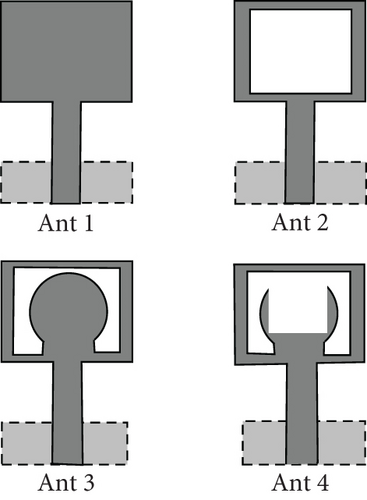

The antenna design development process to achieve triple-band operation for WLAN/WiMAX applications is shown in Figure 2, and the corresponding S11 results are shown in Figure 3. It is clearly evident that Antenna I is a modified rectangular printed monopole antenna with defective ground plane as shown in Figure 2. It has two operating bands 2.60–3.60 and 5.1–6.39 GHz as illustrated in Figure 3. Antenna I has now been modified to Antenna II to achieve greater compactness by cutting a wide slot in the geometry to form a rectangular ring monopole antenna as shown in Figure 2b. It is a common compact antenna with simple structure and has two operating bands 2.44–3.04 and 5.33–58 GHz. Additionally, Antenna 2 has been modified to Antenna 3 by adding a circular-shaped stub to excite an additional resonance band at approximately 3.3 GHz as shown in Figure 2c. These three resonant bands of Antenna 3 are observed as follows: 2.40–2.53, 3.10–3.91, and 4.77–5.86 GHz; see Figure 3 (red curve). Finally, the circular-shaped bar of Antenna 3 was slotted by a rectangular shape to achieve better impedance matching at higher bands as shown in Figure 2. Now, illustrated in Figure 3, Antenna 4 is excited at all three resonance bands with good impedance matching at 2.36–2.70, 3.21–3.92, and 4.91–5.94 GHz. These bands clearly meet the frequency band requirements for WLAN/WiMAX and 5G applications.
2.1. Surface Current Density
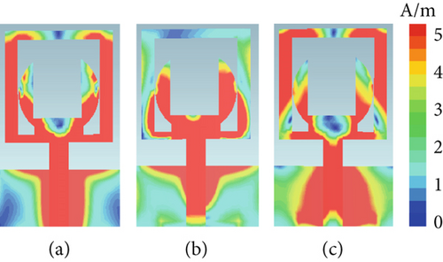
Furthermore, an attempt was made to study the excitation of the resonant bands by various parameters of the antenna with the help of the surface current distribution on the proposed antenna. Thus, we study simulated surface current distributions which are plotted at sampling frequencies 2.55, 3.42, and 5.53 GHz, as shown in Figure 4. After analyzing Figure 4a, we see that strong surface currents are distributed around the rectangular-shaped ring strip concluded to be primarily responsible for the excitation of the lower band at 2.5 GHz, as expected. Furthermore, study the current distribution on the proposed antenna at 3.42 GHz resonant frequency (see Figure 4b). It is clear now that the surface current distributed in the left over portion after cutting of rectangular slot in the circular strip is responsible for the excitation of these frequencies. This explanation also matches the design steps discussed above in that the resonance is generated by the left over portion of circular-shaped strip. The current distribution shown in Figure 4c gives an estimate that it is about the excitation of the third band around 5.5 GHz, which is mainly caused by the lower rectangular ring-shaped radiator and ground plane.
2.2. First Resonance
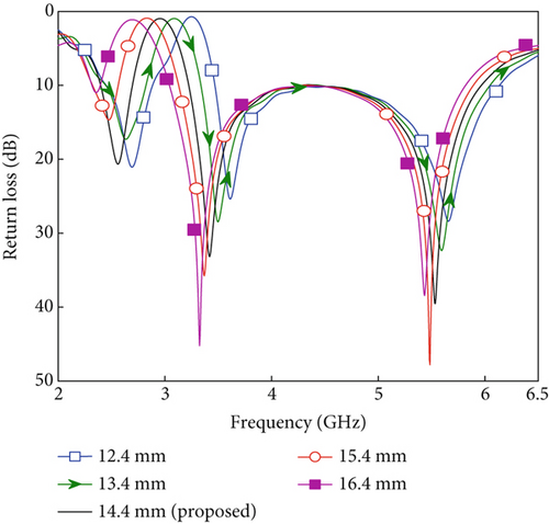
The suggested Equation (1) can be verified by looking at Figure 5 for the lower resonant frequency of the proposed antenna. The effect of varying slot length L1 from 12.4 to 16.4 mm on the return loss parameter of the projecting antenna is displayed in Figure 5. It is evident that the boundary conditions required for the excitation of the lower band are circumvented by changing the value of slot length L1. Thus, the slot length L1 was considered to be 14.4 mm to excite the lower resonance band at 2.5 GHz. The simulated frequency and frequency evaluation using the proposed design equation for different values of slot length L1 are tabulated in Table 3.
| L1 (mm) | Lr1 (mm) | Resonant frequency (GHz) | |
|---|---|---|---|
| Design equation | Full-wave simulation | ||
| 12.4 | 39.95 | 2.53 | 2.66 |
| 13.4 | 40.95 | 2.47 | 2.58 |
| 14.4 | 41.95 | 2.41 | 2.5 |
| 15.4 | 42.95 | 2.36 | 2.38 |
| 16.4 | 40.95 | 2.30 | 2.25 |
The simulated frequency and the frequency calculated using the proposed design equation are in good agreement with each other as is evident from Table 3 and Figure 5.
2.3. Second Resonance
The suggested Equation (3) can be verified by looking at Figure 6 for the middle band resonant frequency of the proposed antenna. The effect of changing the length W2 from 5.6 to 9.6 mm on the return loss parameter of the projecting antenna is shown in Figure 6. It is clear that the boundary conditions required for the excitation of the middle band are circumvented by changing the value of the length W2. Thus, the length W2 was considered to be 7.6 mm to excite the middle resonance band at 3.5 GHz. The simulated frequency and frequency evaluation using the proposed design (Equation 3) for different values of length W2 are tabulated in Table 4.
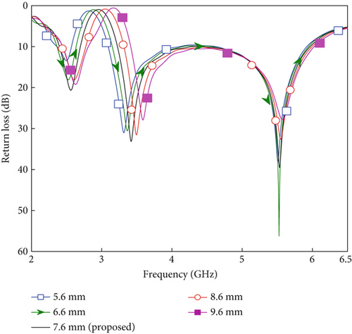
| W2 (mm) | Lr1 (mm) | Resonant frequency (GHz) | |
|---|---|---|---|
| Design equation | Full-wave simulation | ||
| 5.6 | 26.8 | 3.28 | 2.66 |
| 6.6 | 27.8 | 3.39 | 2.58 |
| 7.6 | 28.8 | 3.51 | 2.5 |
| 8.6 | 29.8 | 3.60 | 2.38 |
| 9.6 | 30.8 | 3.77 | 2.25 |
The simulated frequency and the frequency calculated using the proposed design equation are in good agreement with each other as is evident from Table 4 and Figure 6.
2.4. Third Resonance
The suggested Equation (4) can be verified by looking at Figure 7 for the upper resonant frequency of the proposed antenna. The effect of changing the length L from 15 to 19 mm on the return loss parameter of the projecting antenna is shown in Figure 7. It is evident that the boundary conditions required for the excitation of the upper band are circumvented by changing the value of the length L. Thus, the length L of the strip was considered to be 17 mm for the excitation of the upper resonance band at 5.5 GHz. The simulated frequency and frequency evaluation using the proposed design (Equation 4) for different values of L are tabulated in Table 5.
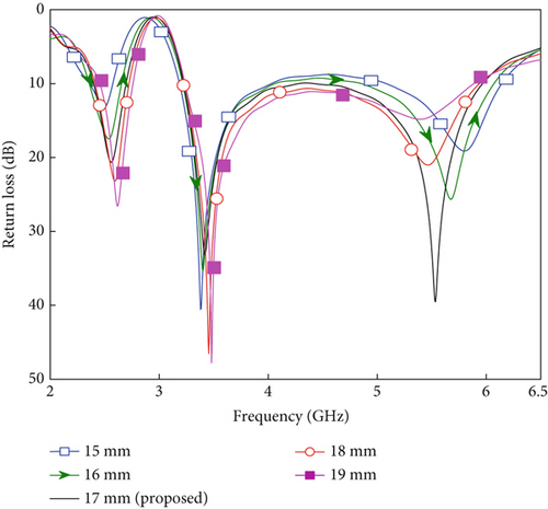
| L (mm) | Lr3 (mm) | Resonant frequency (GHz) | |
|---|---|---|---|
| Design equation | Full-wave simulation | ||
| 15 | 17.00 | 5.95 | 5.74 |
| 16 | 17.67 | 5.72 | 5.59 |
| 17 | 18.33 | 5.52 | 5.5 |
| 18 | 19.00 | 5.32 | 5.44 |
| 19 | 19.67 | 5.14 | 5.38 |
The simulated frequency and the frequency calculated using the proposed design equation are in good agreement with each other as is evident from Table 5 and Figure 7.
3. Experimental Results and Discussion
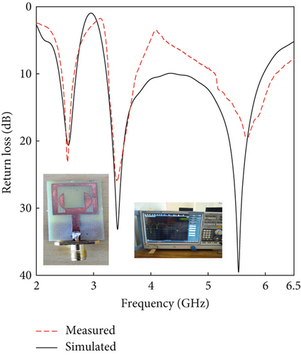
The above sections relate to antenna designing, which is explained with the help of simulated results obtained using CST software. Now, it is time to verify the above results with measurements. Hence, the proposed design was fabricated and measured using PCB machine and vector network analyzer inside an 100 dB RF shielded anechoic chamber available in the laboratory of our institute. There are two positioners inside the anechoic chamber, one of which is fixed and the other is a rotatable positioner. A comparison of measured return loss versus simulated is shown in Figure 8. It is clearly visible that the measured return loss corroborates well with the simulated results. Also from Figure 8, it is firmly established that the antenna can simultaneously support WLAN (2.4/5.2/5.8 GHz), WiMAX (2.5/3.5/5.5 GHz), and 5G sub-6 GHz (450 MHz to 6 GHz) frequencies. As per the measured results, it is found that the proposed compact antenna can effectively cover three distinct bands, I from 2.3 to 2.70, II from 3.2 to 3.92, and III from 5.1 to 5.9 GHz.
Another important parameter to measure antenna performance is the radiation pattern which was measured and compared with the simulated for all three bands at different sampling frequencies, that is, 2.48, 347, and 547 GHz. The antenna under test (AUT) is positioned in front of a calibrated reference horn antenna with known gain, at a minimum distance of d = 2D2/λ inside an anechoic chamber. Here, D denotes the largest dimension of the AUT, d is the separation between the AUT and the reference antenna, and λ is the operating wavelength. To measure the YZ plane radiation pattern, the AUT is fixed at φ = 00 and rotated from θ = 00 to 1800 (vertical scan), as shown in the upper left and lower right parts of Figure 9. Similarly, for the XY plane radiation pattern, the AUT is fixed at θ = 900 (horizontal scan) and rotated from φ = 00 to 3600, as depicted in the upper right and lower left sections of Figure 9. This entire measurement process was controlled by a computer located in the lab outside the chamber. Further, the step size during the measurement was taken very small which gives a very smooth graph. As seen from Figures 9a, 9b, and 9c, it is almost omnidirectional. Radiation patterns obtained in the copolar plane and bidirectional in the cross-polar plane at all three frequencies. As for the targeted antenna, radiation pattern should be omnidirectional. These results confirm the good radiation performance at the targeted band.
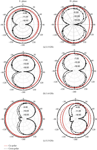
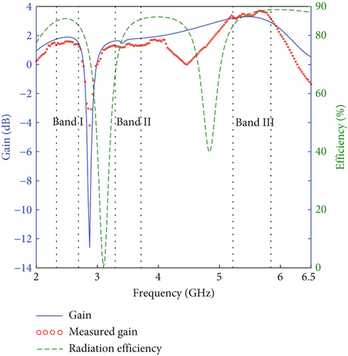
Figure 10 shows the combined graph of measured and simulated gain and efficiency. It is observed that the gain for the proposed antenna shows an appreciable gain from 1.5 to 3.5 dBi for all three bands, whereas the antenna radiation efficiency remains more than 85% for all three resonant band. The radiation efficiency of the antenna must be greater than 50% for effective radiation.
4. Conclusion
According to the above research, an antenna aimed at combining WLAN, WiMAX, and 5G communication standards into a single wireless device that can promote triple-band operation was successfully designed and achieved. The proposed antenna was consist of circular-shaped rectangular slotted radiator encircled by a rectangular ring and a defected ground plane. The designed antenna has a compact size of 20 × 32 mm2 (0.16λ0 × 0.256λ0). The optimum dimensions were obtained using parametric studies of the key parameters of the antenna. The proposed antenna offers three different bands—I 2.3–2.70, II 3.2–3.92, and III 5.1–5.9 GHz, which clearly covers the entire WLAN (2.4/5.2/5.8 GHz), WiMAX (2.5/3.5/5.5), and 5G bands. Good agreement of the simulation results with the measured results was obtained, and it was proved that the antenna can simultaneously operate on WLAN (2.4/5.2/5.8 GHz), WiMAX (2.5/3.5/5.5 GHz), and 5G frequency bands. This antenna is a suitable candidate for a device that can be used simultaneously for these three services including WLAN, WiMAX, and 5G services.
Conflicts of Interest
The authors declare no conflicts of interest.
Funding
No funding was received for this manuscript.
Open Research
Data Availability Statement
Data sharing is not applicable to this article as no new data were created or analyzed in this study.


