Automatic Antenna Orientation Using the Algorithm Compatible With the Wireless Energy Harvesting System
Abstract
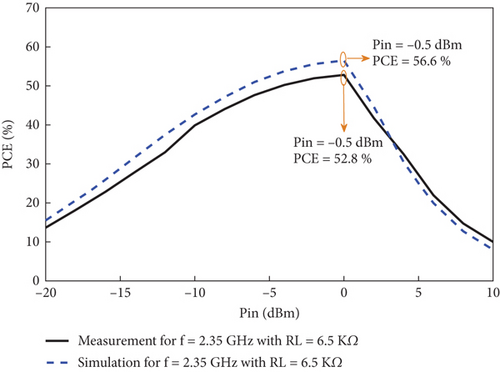
In wireless telecommunication systems, the precise adjustment of the antenna direction has a direct effect on the quality of the received signal. In this article, a new routing algorithm is designed using the wireless energy harvesting (WEH) technology from electromagnetic waves to adjust the orientation of the receiver antenna. The algorithm is simulated for routing in TDD LTE cellular network at 2.35 GHz frequency. The proposed antenna in this article is a cross-dipole type with dual-polarization RHCP and LHCP, and its measured impedance bandwidths are 1.97–2.70 GHz at Port 1 and 1.96–2.72 GHz at Port 2. Also, 7.45 dBic peak gain and end-fire radiation capability of the proposed antenna are among the advantages of the automatic routing system. The proposed rectifier for WEH uses the voltage doubler technique. A new construction of microstrip elements has been used for the impedance matching network (IMN). The fabricated rectifier at 2.35 GHz can provide PCE = 52.8% at −0.5 dBm input power, which is suitable for WEH.
1. Introduction
It is expected that wireless sensing and positioning will be more practical in future generations of telecommunication systems [1–3]. The technology of finding the direction of maximum radiation of electromagnetic waves can be used to identify the exact position of radars in addition to the networks providing telecommunication services. For example, in systems equipped with solar tracking, the maximum power point tracking (MPPT) method is used to achieve maximum power. The use of single-axis and two-axis detectors in the accurate detection of the maximum angle of sunlight increases the output efficiency in these systems [4–6]. In wireless communication systems, determining the correct direction of antenna placement plays a significant role in acceptable reception and transmission of radio signals. In directional antennas, the precise installation of the antenna in the direction of receiving the maximum signal radiation increases the signal-to-noise ratio (SNR). In this article, by using the wireless energy harvesting (WEH) technique and without using the analysis of SNR, the receiver antenna is set in the optimal position. In telecommunication systems where the exact position of the service antenna is not known for the receiver antenna, such as cellular networks and WIMAX and radar systems, the best position for installing the receiver antenna can be determined using the WEH system. The mobile cellular network comprises hexagonal cells, and each BTS system often includes three sectors, each covering about 120° [7]. Limiting the radiation power of cells in the advanced mobile phone system (AMPS) is done to prevent interference between the transmitters of each network cell and its neighboring cell [8]. Therefore, to set the client’s antenna in the optimal position, the angle of azimuth and elevation of the antenna should be determined so that the maximum energy is received by the antenna. In this article, the WEH technique and algorithmic design are used for fast convergence to achieve the position of receiving the maximum radio signal power. WEH requires designing a rectenna system consisting of a radio receiving antenna and a rectifier circuit with an impedance matching network [9]. This paper presents a new design of a cross-dipole antenna with circular polarization (CP) and a 2.35 GHz frequency coverage used in the TDD LTE network. The proposed rectifier uses the Cockcroft–Walton voltage multiplier model and uses a compact impedance matching network with a new design, which reduces the dimensions of the rectifier structure.
2. Designing the Maximum Point Detector Algorithm
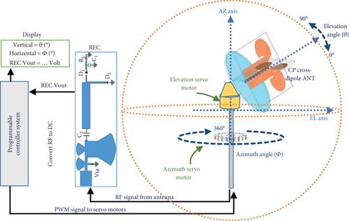
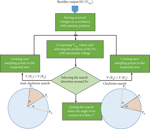
The algorithm presented in this paper is based on the perturbation and observation (P&O) algorithm, which is optimized for comparing local maxima and tracking the absolute maximum with the least number of samplings. The P&O algorithm is a process in which one variable is defined as disturbance, and the effect of disturbance is observed in other variables [10]. The proposed algorithm, assuming that in the test environment, there is electromagnetic wave radiation caused by the radiation of at least one transmitter antenna at a particular frequency, can harvest wireless energy by rotating 360° on the azimuth axis and 90° on the elevation axis and by analyzing the WEH output voltage tracks the exact radiation path. In this analysis, the target point is expressed by three parameters (Vout, ɸ, and Ɵ). Vout is the DC voltage of the rectenna output, which is considered an observation parameter in the algorithm; ɸ is the azimuth angle; and Ɵ is the elevation angle. ɸ and Ɵ are considered turbulence parameters. Figure 1 shows the general structure of the proposed design of this article. In the test environment with waves caused by several transmitters at the same frequency, we must design a comparison algorithm to detect the path of maximum radiation.
2.1. Performance of the Proposed Algorithm
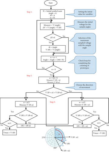
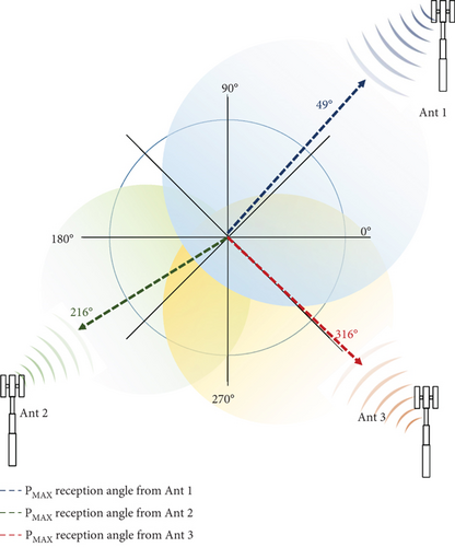
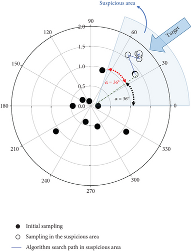
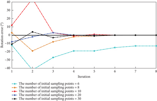
The performance of the proposed algorithm by a simulation was carried out in MATLAB software assuming the presence of three transmitter antennas in the surrounding environment and angle ɸ = 49° as a sample with maximum received voltage. In Figure 3b, the algorithm starts sampling by selecting N = 10. The black circles show the prototypes that the algorithm detects the angle ɸ = 37° corresponding to the maximum voltage by analyzing the voltages of each prototype. In the next step, according to Equation (2), by choosing α = 36, a comparison between the voltage angles of ɸ = (α − 37)° and ɸ = (α + 37)° has been made, and the result of the comparison causes the detector to move in the anticlockwise direction. In Figure 3, the hollow circles are the angles selected for sampling after determining the scanning direction, which in N = 10 after six iterations of the algorithm reached an angle of 49°. A decrease in N means a decrease in initial sampling. In the performed simulation, choosing N < 8 causes a significant error in determining the desired angle. As seen in Figure 4, choosing N = 6 causes the detection of the angle corresponding to a local maximum, far from our desired angle, and the system has an error. In Figure 4, some examples are simulated with variable N. Choosing several initial samples higher than 8 reduces the tracking error to zero. The parameter N plays a key role in the proposed algorithm for finding the maximum radiation direction. According to the simulation results in Figure 4, increasing the number of initial samples reduces the angle error, and the target position is obtained faster. To obtain the minimum number of prototypes (N) to achieve the target angle without error, it is necessary to have the radiation parameters of the antenna used. Antennas with end-fire radiation capability usually have high gain. In receivers that use parabolic antennas to receive signals, due to the relationship between the antenna aperture and its gain, we can have the appropriate gain for the antenna by choosing an antenna with the appropriate aperture at the desired wavelength. In Vivaldi antennas and dipole antennas with directional radiation, the value of the parameter N can also be determined by considering the antenna gain. In other words, the higher the gain of the receiver antenna, the lower the number of minimum initial samples can be, and a ratio between the antenna gain and N can be imagined.
2.2. Hardware Details for Implementing Antenna Rotation
- •
Control board: This hardware usually includes a microcontroller to execute the programmed algorithm and generate a pulse width modulation (PWM) signal. Its main task is to control the rate and direction of rotation of the servo motors.
- •
Servo motors: For antenna rotation, due to the lightness of the proposed antenna, standard digital servo motors can be used, which require a voltage between 4.8 and 6 volts and are suitable for applications such as tracking due to their fast response and high accuracy.
3. Design of Radio Wave Energy Harvesting System
To sample the selected angles, a rectenna system consisting of a receiving antenna, a rectifier, and an impedance matching circuit is required. Figure 5 shows the general block diagram for the rectenna system. The proposed antenna in this article is a cross-dipole antenna. The proposed rectifier is a half-wave rectifier and uses SMS-7630 Schottky diodes [11]. An impedance matching network is required to connect the rectifier circuit to the dipole antenna. In this paper, a new structure consisting of curved stubs and via connection is used for impedance matching. The proposed structure for the impedance matching network reduces the dimensions of the rectifier.

3.1. RF to DC Converter Design
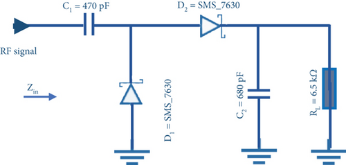
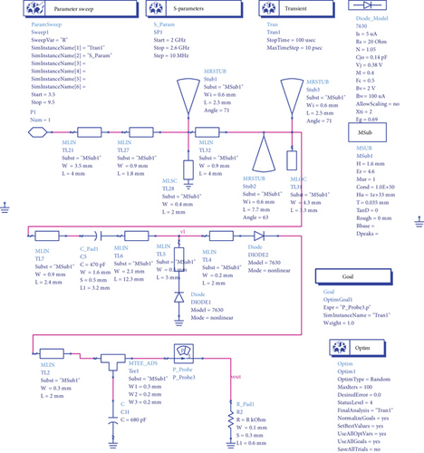
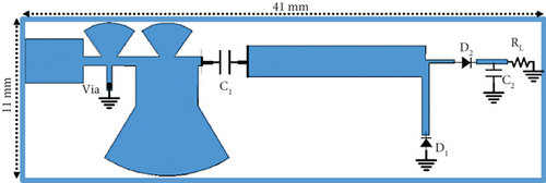
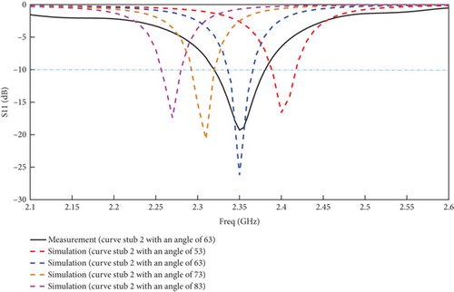
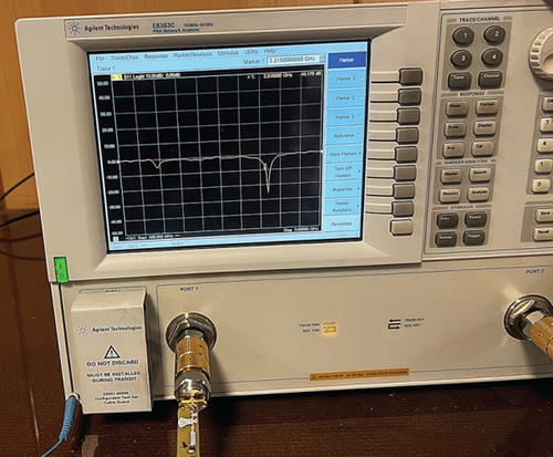
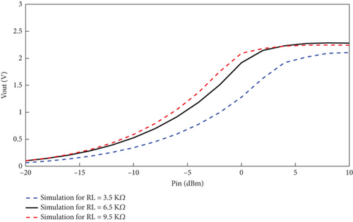
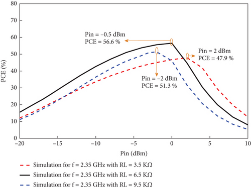
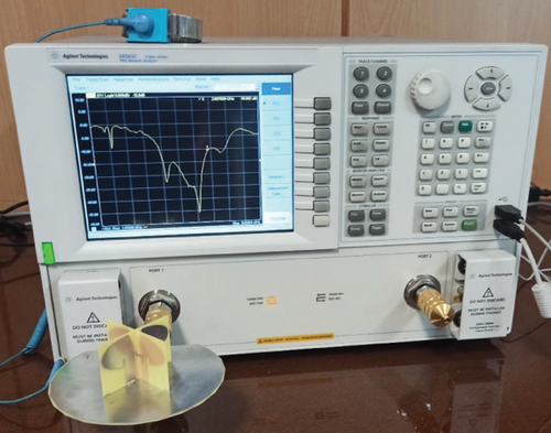
The use of curve stubs in the impedance matching network has made the working frequency of the rectifier controllable as shown in Figure 7a. By changing the angle of curve stub 2, the working frequency of the rectifier shifts. The proposed rectifier in 41 mm × 11 mm × 1.6 mm is designed and built on an FR4 substrate with a dielectric constant of 4.6 in ADS. S11 parameter analysis by ADS software shows 20 MHz (2.34–2.36 GHz) bandwidth coverage at Pin = −10 dBm input power and RL = 6.5 kΩ selection. Figure 7b shows the measurement of rectifier S11 in the laboratory by the network analyzer (NA) E8363C from Agilent Technologies. In Figure 7a, the black curve defines the coverage range of the constructed rectifier from 2.32 to 2.37 GHz. Rectifier efficiency calculation uses Relations (6) and (7) for simulation analysis and laboratory measurement [17]. Figure 8 shows that the correct choice of load resistance (RL) has a direct effect on the RF to DC conversion efficiency. The analysis of PCE at powers between −20 and 10 dBm in Figure 8 shows that the maximum value of PCE is at resistor RL = 6.5 kΩ and input power Pin = −0.5 dBm. PCEmax at low input powers is one of the advantages of the proposed rectifier, which makes the structure more practical. To compensate for the efficiency at low input powers, RF signal amplifiers can be used at the input of the rectifiers to obtain an acceptable DC signal at the output of the rectenna.
3.2. The System’s Sensitivity to Variations in RL
The RL resistor in the rectenna circuit plays the role of the rectifier output terminal through which power can be delivered. According to the condition of maximum power transfer, to be able to deliver maximum power from the antenna to the rectifier and finally to the load, there must be an acceptable impedance match between RL and the rectifier output impedance. Therefore, microstrip elements are used at the rectifier output and the load resistance RL. If RL is not the same as the rectifier output impedance, the rectenna efficiency decreases, and part of the power is reflected.
4. Characteristics of the Receiving Antenna
The design of the appropriate receiver antenna is of particular importance for this article. Polarization should be considered one of the radiation parameters of the antenna to harvest the energy of radio waves. Having CP allows the antenna to reduce the fading of the multipath radio signal and is also more helpful in harvesting electromagnetic energy. In WEH, the use of CP antennas is superior to linearly polarized (LP) antennas. In LP antennas, which usually have a simpler structure, if the antenna orientation is adjusted correctly, it can receive energy well. However, if it is not aligned, the efficiency is greatly reduced. CP antennas have better efficiency in energy harvesting in most conditions due to their independence from orientation. This feature makes CP antennas ideal for WEH systems. In other words, in CP, waves are sent and received circularly. This feature allows the receiving antenna to receive energy more effectively regardless of its orientation relative to the transmitter. CP antennas can be designed in two modes: right-handed CP (RHCP) and left-handed CP (LHCP) [18–22]. The possibility of switching between RHCP and LHCP improves the capacity of telecommunication systems, so the antenna considered for this article has RHCP and LHCP capabilities. The antenna proposed in this article is of cross-dipole type, and by using a pair of baluns and a hybrid feed structure, it has been able to achieve dual CP.
4.1. Implementation of Dual CP Using Integrated Balun Network
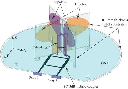
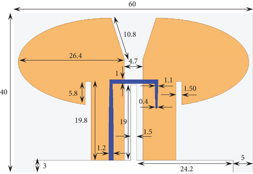
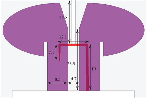
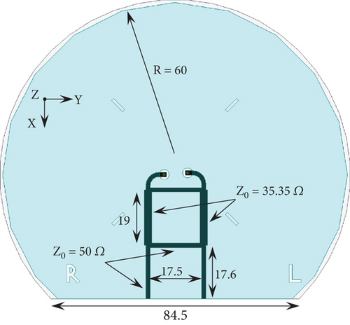
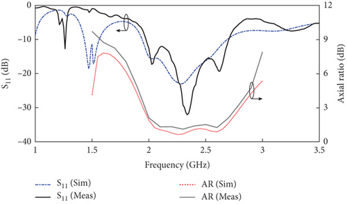
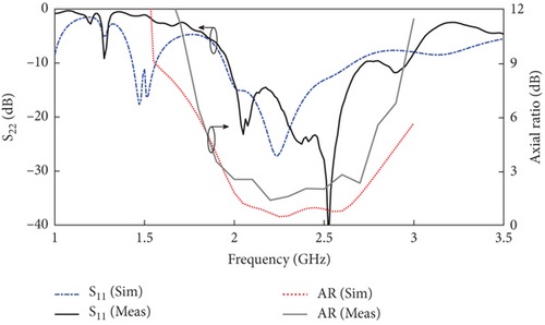
Figure 9 shows the arrangement of the proposed cross-dipole antenna elements along with the dimensions of the structure. The dipole arms are placed vertically on a substrate made of FR4 material with a dielectric constant of 4.4 and a loss tangent of 0.02. The thickness of the substrate is 0.8 mm, and one side of it is the ground plane, and the other side is the hybrid network. The balun used in this antenna is Γ-shaped, which is connected to the feeding network behind the substrate by a small connector passing through a hole [23]. The Γ-shaped balun creates a balance between the dipole arms by electromagnetic coupling [24–27]. Figure 10 shows the curve related to the dipole return loss and axial ratio (AR) with the presence of Γ-shaped baluns. According to the measurements, the proposed CP antenna has an impedance bandwidth of 1.97–2.70 GHz at Port 1 and 1.96–2.72 GHz at Port 2. The analysis of the AR curve presented in Figure 10 states that the final fabricated antenna for port-R and port-L has an AR value of less than 3 dB in the frequency band of 1.95–2.77 GHz and 1.93–2.72 GHz, respectively, which indicates the radiation of the antenna is with CP in the mentioned bands.
4.2. The Design of the Quadrature Hybrid Coupler
In radio communication systems, it is customary to use 90° hybrid couplers as one of the methods of dividing the input signal into two similar signals with a 90° phase difference. In this article, a 90° hybrid coupler is used to transfer the same power to cross-dipoles. In other words, the 90° hybrid coupler for the proposed cross-dipole feeding creates a 90° phase difference between the signals by maintaining the amplitude of the signal between the dipoles [23]. It is called a quadrature hybrid coupler because of the 90° phase difference in the 90° hybrid coupler output. Figure 9a shows the structure of the quadrature coupler with four ports. The inputs of the coupler are Ports 1 and 2. The signals in the output ports have the same amplitude, but they are 90° different in terms of phase. The proposed coupler is printed according to the dimensions specified in Figure 9d on an FR4 substrate with a thickness of 0.8 mm and a dielectric constant of 4.4.
4.3. Analysis of Proposed Cross-Dipole Antenna
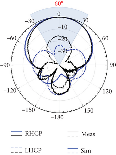
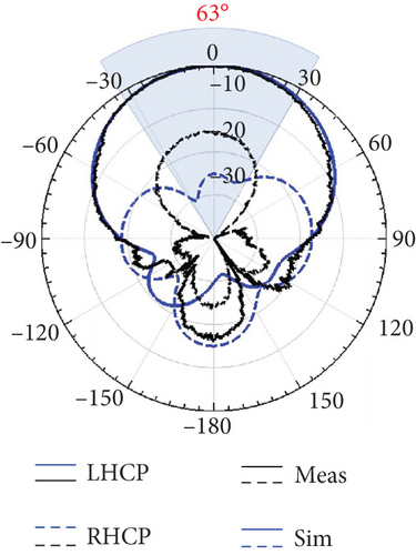
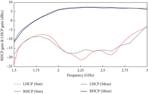
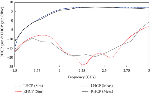
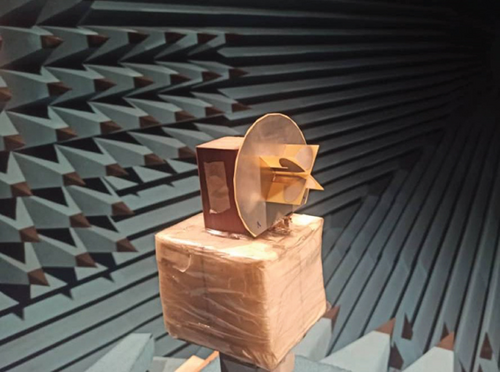
Figure 9a shows the cross-dipole mounted on the ground plane and fed by baluns connected to the quadrature hybrid coupler. Ports 1 and 2 of the coupler are considered the input ports of the final antenna. Port 1 is defined as port-R, and Port 2 is defined as port-L. Excitation of port-L means the antenna activation in the LHCP radiation mode. In this case, the input signal to port-L is distributed between two dipoles with the same amplitude and 90° phase difference. In the LHCP state, the phase of the Dipole 2 signal is 0°, and the phase of Dipole 1 is 90°. If the excitation signal is applied to port-R, the antenna radiation is activated in the RHCP mode. The scattering parameters of the final antenna have been simulated using HFSS software. The parameters of the fabricated antenna in the laboratory have been measured. The final antenna covers the operating frequency of the rectifier in both modes. Figure 11 shows the radiation pattern of the final antenna at a frequency of 2.35 GHz. The antenna pattern is normalized and plotted in two modes, RHCP and LHCP, and shows the stability of the pattern. A difference of more than 15 dB between the co- and cross-polarization in the excitation of the input ports indicates that the proposed cross-dipole emits the RHCP radiation mode in Port 1 and the LHCP radiation mode in Port 2. The ground plane provides an acceptable unidirectional radiation reflector for the subject of this paper. Considering the shape of the pattern in both input ports and the HPBW angle, it can be said that the pattern has end-fire radiation. Figure 12 shows the final antenna gain for stimulating both antenna input ports. The experimental results confirm the performance of the proposed CP antenna, revealing a peak gain of 7.45 dBic at 2.30 GHz for Port 1 and 7.39 dBic at 2.60 GHz for Port 2. Figure 13 shows the measurement setup of antenna parameters in the laboratory. The return loss measurement of the final fabricated antenna by NA E8363C from Agilent Technologies has been done. Comparing the results of Figure 10 shows a small difference between the measured and simulated bandwidths, and the fabricated antenna has adequate coverage at 2.35 GHz frequency.
5. Conclusion
In this work, topology was presented to find the maximum path of received radio wave radiation. This rectenna system uses a rectifier at 2.35 GHz frequency, where a new arrangement of microstrip elements is provided for better impedance matching and reducing the dimensions of the rectifier structure. In the laboratory measurement, we obtained an acceptable PCE of 52.8% from the manufactured sample. The proposed antenna also has the capability of CP in both RHCP and LHCP modes with end-fire radiation and a peak gain of 7.38 dBic at 2.35 GHz frequency. The CP radiation capability in the antenna helps us reduce the alignment problem and polarization loss. Table 1 compares the RF to DC converter of this paper and previous similar works. The impact of the new IMN design in this article has reduced the dimensions of the rectifier compared to [16, 28]. Also, compared to [28–33], the proposed rectifier can provide an acceptable efficiency in input power of less than 0 dBm. The radiation pattern with dual CP of the antenna presented in this article is more practical for the automatic orientation of the proposed antenna than the sources in Table 1. The algorithm presented in this article can guide the rotation direction of the antenna from the rectenna sample voltage. The ability to track the maximum path of radio wave radiation was simulated by the algorithm with an example of a TDD LTE cellular network at a frequency of 2.35 GHz. In the lowest iteration, the algorithm adjusted the antenna with the minimum initial sampling of N = 10 to receive the maximum power. In the technique presented for this work, the cross-dipole CP antenna elements and the rectifier were fabricated tested and evaluated in the laboratory. Considering the main goal of this technique, which is to find the direction of maximum RF signal radiation, various applications can be considered for it in the future, which require a programmed control system with the proposed algorithm and the installation of digital servo motors with interfaces to implement it in practice. Tracking the position of radars due to the high transmission power of radar systems can be one of the future works for developing this system. Another application that can be imagined is satellite trackers, which can be used to scan the position of satellite signals with the proposed technique at a minimal cost.
| Ref | Freq (GHz) | Antenna dimensions (λ3) | Antenna polarization type | Antenna peak gain (dBic) | Rectifier dimensions (λ3) | Peak PCE (%) Pin (dBm) | Measured maximum PCE (%) |
|---|---|---|---|---|---|---|---|
| 16 | 3.08, 3.45, 4.31, 5.11, 5.49 | 0.618 × 0.618 × 0.015 | RHCP/LHCP | NR | 0.824 × 0.824 × 0.015 | −5, 0, 3, 6, 3 | 30.2, 45.6, 16.4, 8.1, 19.6 |
| 28 | 5.8 | NR | CP | NR | NR | 27 | 43 |
| 29 | 3.5, 5.8 | 1.117 × 0.764 × 0.008 | NR | 10.2 | NR | 0 | 44, 29 |
| 30 | 3.1 | 0.208 × 0.291 × 0.016 | NR | 11 | NR | 7.5 | 18 |
| 31 | 1.84, 2.04, 2.36, 2.54, 3.3, 4.76, 5.8 | 0.333 × 0.308 × 0.004 | NR | 4.3 | 0.333 × 0.259 × 0.004 | 4 | 44.4, 43.9, 45.4, 43.4, 36.1, 32.4, 28.3 |
| 32 | 10 | 0.568 × 0.568 × 0.027 | NR | NR |
|
|
|
| 33 | 3.1, 5.75 | 0.614 × 0.625 × 0.16 | Linear | 7.47 | 0.979 × 0.375 × 0.016 | 8.5, 6.5 | 56.3, 33.4 |
| This Work | 2.35 | 0.944 × 0.803 × 0.299 | RHCP/LHCP | 7.45 | 0.322 × 0.086 × 0.012 | −0.5 | 52.8 |
Conflicts of Interest
The authors declare no conflicts of interest.
Funding
No funding was received for this research.
Open Research
Data Availability Statement
Research data are not shared.


