A Fast Electromagnetic Radiation Simulation Tool for Finite Periodic Array Antenna and Universal Array Antenna
Abstract
The domain decomposition method (DDM) enables efficient simulation of electromagnetic problems in large-scale array antennas using full-wave methods on moderate hardware. This paper introduces and compares two nonoverlapping DDMs serving as preconditioners with outstanding simulation efficiency. The first method targets finite periodic array antennas by transforming a single array unit rather than explicitly modeling the entire array, effectively leveraging repetitive structures to significantly reduce memory usage and computation time. The second method applies to universal array antennas with arbitrary geometries, employing both planar and nonplanar mesh-based domain partitioning at subdomain interfaces for flexible modeling of complex arrays. To further enhance computational performance, we propose a parallel multilevel preconditioner based on the block Jacobi preconditioner, thereby accelerating the solution efficiency of subdomain matrix equations in both methods. Additionally, since the choice of domain partitioning method significantly impacts the computational efficiency of DDMs, we propose three different subdomain partitioning strategies. These strategies enable us to accelerate computations while expanding our capacity to simulate a wider variety of types of cases. We developed a fast electromagnetic radiation simulation tool utilizing these techniques. Simulations of exponentially tapered slot (Vivaldi) antenna arrays and antenna arrays with radomes demonstrate that our tool achieves accuracy comparable to commercial software, and notably, our tool outperforms commercial software in terms of the speed of iterative solutions.
1. Introduction
Array antennas are widely used in medical imaging, remote sensing, and other wireless communication systems because of their significant performance advantages [1, 2]. To achieve a broader range of functionalities, designers typically employ antenna elements with intricate geometric configurations. For example, substrate-integrated waveguide array antennas use a stacked structure to fabricate a multifunctional system [3]; magnetoelectric dipole antenna arrays adopt electromagnetic bandgap structures to reduce leaky wave losses and narrow beamwidth in the E-plane [4, 5]. In designing an array antenna, it is vital to consider the dimensions of the elements, the spacing of the array, the configuration and positioning of the feed, and the electromagnetic interactions within the unit structure. For realistic models consisting of hundreds or thousands of elements, experimental design methods may pose significant financial and personnel challenges. Consequently, numerical simulation plays a vital role in the design of array antennas [6].
Among various numerical simulation methods, the finite element method (FEM) is widely utilized due to its effectiveness in addressing complex geometric configurations and highly inhomogeneous materials [7, 8]. However, FEM requires considerable memory resources and computational time. To enhance simulation efficiency, researchers have developed various algorithms to solve FEM matrix equations, including incomplete lower–upper (LU) factorization [9], preconditioned iterative methods, and multilevel iterative methods [10, 11]. While these approaches have improved computational efficiency to some extent, simulating large-scale array antennas on medium-scale hardware remains challenging. Recently, the nonoverlapping domain decomposition method (DDM) has emerged as a potential solution for the simulation of large array antennas.
Nonoverlapping DDM partitions the original problem domain into smaller, nonoverlapping subdomains [12, 13]. These adjacent subdomains are coupled through transmission conditions (TCs) [14, 15], and an iterative process updates unknown variables until convergence. To effectively address large-scale electromagnetic problems, researchers have made extensive efforts in this area. Firstly, the Robin-type TC [16, 17] is introduced to accelerate the convergence of nonoverlapping DDM. In this context, S. Lee, Vouvakis, and J. Lee introduced a “cement” technique [14, 18] to allow nonmatching grids between neighboring subdomains. This method is extremely efficient for problems with geometric repetition. Subsequently, Zhao et al. presented a DDM as a preconditioner [19], enhancing the stability of iterative solutions for matrix equations and reducing memory requirements. Although very successful for finite periodic problems, these methods are less efficient when there is little or no repetition in the problem domain. To address problems exhibiting little or no periodicity, Rawat introduced a new interior penalty–domain decomposition method (IP-DDM) [20] that does not require auxiliary variables and adopts matching grid partitioning. Unlike previous methods, IP-DDM allows subdomain interfaces to be nonplanar. The subdomains can, therefore, take on any shape, making IP-DDM suitable for simulations involving array antennas of all types.
To enhance the efficiency of array antenna radiation simulations, this paper explores the finite element DDM. The primary contributions of this study are summarized as follows: (1) We investigate two distinct nonoverlapping DDMs as preconditioners. One is tailored for simulating periodic array antennas with repetitive structures, and the other is designed for array antennas with arbitrary shapes; (2) by integrating parallel computing techniques with our prior work on efficient preconditioners [21, 22], we propose a parallel multilevel preconditioner for nonoverlapping DDM, improving the computational efficiency of the resulting system matrix equations; (3) we introduce a rapid electromagnetic radiation simulation tool designed for both finite periodic array antennas and array antennas with arbitrary shapes, leveraging two distinct DDMs. Notably, we have incorporated various partitioning strategies within the tool’s preprocessing module [23] to accommodate different DDMs. For finite periodic array simulations, users need only model the unique, nonrepetitive array units. Conversely, for universal array simulations, the tool expedites domain partitioning via two distinct mesh partitioning approaches. The rest of the article is organized as follows: Section 2 introduces the theoretical foundations of two different finite element DDMs. In Section 3, we propose a parallel multilevel preconditioner. Section 4 presents the framework of the tool and domain partitioning strategies. Section 5 presents some examples. Finally, in Section 6, we conclude the paper with our findings.
2. The Theory of DDM
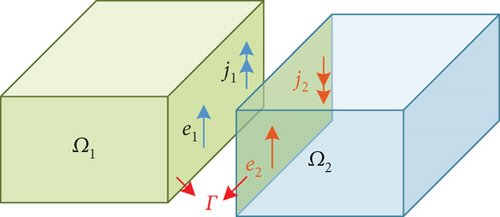
For simplicity and without loss of generality, we only consider partitioning the problem domain Ω into two nonoverlapping subdomains Ω1 and Ω2, as illustrated in Figure 1. The exterior boundary ∂Ω is partitioned into two subboundaries, namely, ∂Ω1 and ∂Ω2. We define the interface between subdomains as Γ = ∂Ω1∩∂Ω2 and denote the outward-directed unit normal to ∂Ωi by .
2.1. The DDM for Finite Periodic Array Simulation
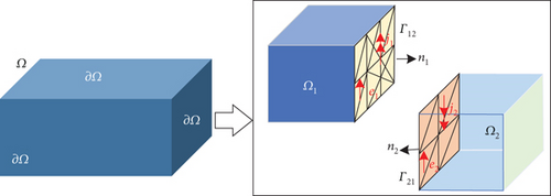
According to the characteristics of FEM, if two subdomains have the same mesh, media properties, and boundary conditions, the matrices Ki and coupling matrices Gij for both subdomains are identical. For periodic arrays with identical antenna elements, we only need to record the matrix formed by a few subdomains to solve Equation (12). Therefore, in the simulation of periodic arrays, this method has a significant advantage in saving memory.
2.2. The DDM for Universal Array Simulation
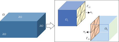
Here, Ei is the column vectors representing unknowns, and bi is the excitation of subdomains. The detailed derivation process, as well as the explicit form of the matrix A, C, and vector Ei, bi, can be found in Reference [20].
3. Parallel Multilevel Preconditioner Technology Based on DDM
Here, L is the ICC factorization, Dr is the diagonal scaling matrix, Pr is the fill-reducing ordering matrix of M11. The detailed information about the preconditioner is provided in Reference [22].
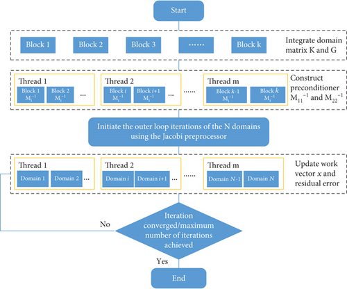
We can execute the multilevel preconditioner within a single domain. For multiple domains, we can implement multilevel preconditioners in parallel for each domain. Figure 4 succinctly encapsulates the parallel multilevel preconditioner technology.
4. Framework of the Tool and Domain Partitioning Technology
As shown in Figure 5, the framework of the tool consists of three layers: a basic layer, a function layer, and a graphical user interface (GUI). The basic layer includes a modeling kernel, a mesh kernel, and a display kernel. These kernel modules can be replaced with alternative open-source or commercial software packages as per the specific requirements.
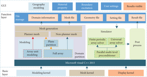
The functional layer comprises four components: file administration, domain partitioning, array antenna simulation, and postprocessing. The finite periodic array solver depicted in Figure 5 is derived based on the theory presented in Section 2.1, while the universal array solver is constructed in accordance with the theory expounded in Section 2.2. The tool’s additional modules can be traced in the References [27, 28]. Next, we emphasize domain partitioning.
4.1. The Domain Partitioning Technique for Finite Periodic Array
For a periodic array antenna, the DDM requires decomposing the computational domain based on the repeated substructures. Considering a 3 × 3 array configuration illustrated in Figure 6, the central blue subdomains represent antenna units with identical structures, while the peripheral subdomains of various colors denote air boxes with distinct boundaries applied.

To simplify DDM, we incorporated a GUI into the tool for managing array units. The execution strategy of GUI is depicted in Figure 7. Initially, the tool is employed to build three-dimensional (3D) models of nine subdomains, each with distinct boundaries. Subsequently, the GUI coordinates the positions of each subdomain. Ultimately, the solver requires only the matrices of these nine subdomains and the positioning data of the other subdomains to simulate the entire array.

4.2. The Domain Partitioning Technique for Universal Array
For universal array simulation, the DDM primarily generates subdomain matrices using conformal meshes. Since there is no requirement for the shape of the interfaces of the subdomain, we accordingly suggest two approaches to accomplish this objective.
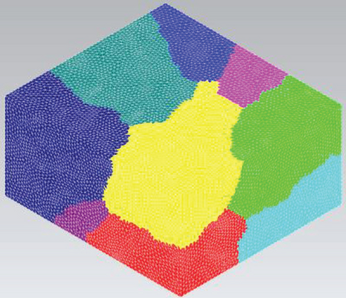
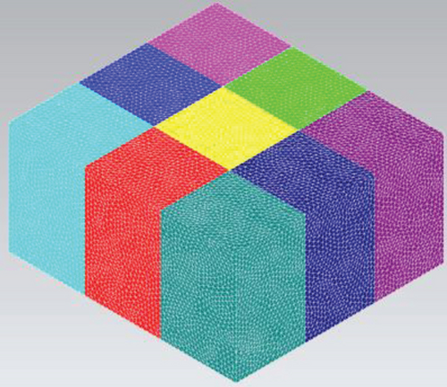
In the first approach, we develop a 3D model of the comprehensive array, generate the finite element mesh, and partition the mesh into distinct subdomains. This method uses graph partitioning theory to automatically divide the area surrounding grid nodes, effectively avoiding the location of the excitation ports. In the second method, we establish a comprehensive array model and invoke a modeling kernel to generate several planes in the x and y directions. We use these planes to segment the array into numerous small hexahedral domains, and a mesh kernel generates a mesh within each hexahedral domain. Therefore, the planar mesh is present at the interface of subdomains. The illustrations of these two approaches are presented in Figure 8.
5. Numerical Results
This section demonstrates the performance of the tool through some numerical examples of practical interest. For the sake of clarity, we refer to the finite periodic array solver and the universal array solver from Section 4 as the periodic solver and universal solver, respectively. Both solvers use the restarted generalized conjugate residual (GCR(15)) [29] and employ open multiprocessing (OpenMP) [30] in the parallel multilevel preconditioner. We set the outer-loop tolerance of DDM to ε = 10−2 and the subdomain iteration tolerance to ε = 10−3. Apart from our tool, the frequency domain solvers of CST Studio Suite (Version 2022) and Ansys high-frequency structure simulator (HFSS) (Version 2020 R2) were also used to calculate and compare the radiation parameters of the examples. Unless otherwise stated, all examples were simulated on a desktop with an Intel Core i9-10980XE processor (3.00 GHz), 256 GB of RAM, and a 64-bit Windows operating system.
5.1. Vivaldi Antenna
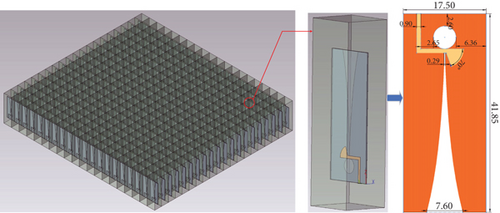
We first chose the Vivaldi antenna element [31–33], due to its complex geometric structure, material properties, and wide range of applications, to verify the universal solver’s accuracy and efficiency. Figure 9 shows the shape, structural dimensions, and materials of the Vivaldi antenna element; additional structural parameters are available in Reference [31]. For this calculation, the universal solver utilizes a lumped port excitation with a normalized impedance of 75 Ω and a frequency of 16 GHz. For comparison, HFSS employs the same settings, configuring the solution type as Driven Solution and setting the solution options to DDM. CST sets the solution type as Domain. To facilitate the comparison of computational performance, all of the solvers implement local mesh refinement to generate comparable mesh counts. The universal solver uses nonplanar meshes. Additionally, HFSS and CST disable adaptive meshing, set the Maximum Number of Passes to 1, and retain all other settings at their default values.

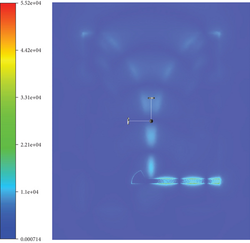
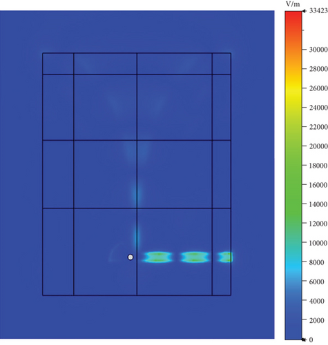
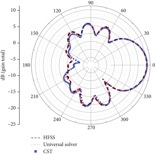
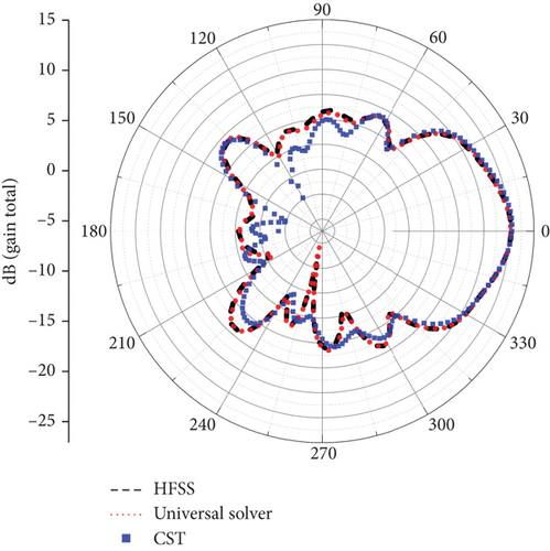
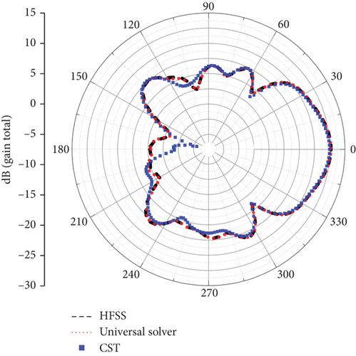
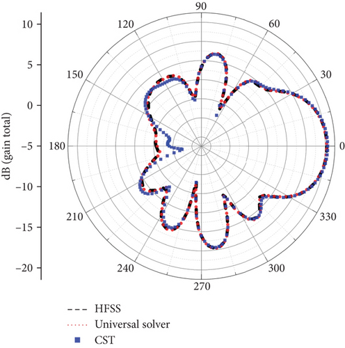
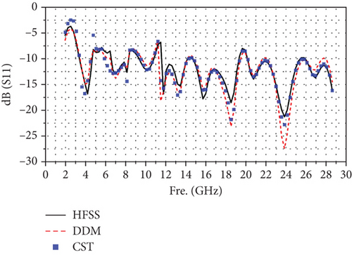
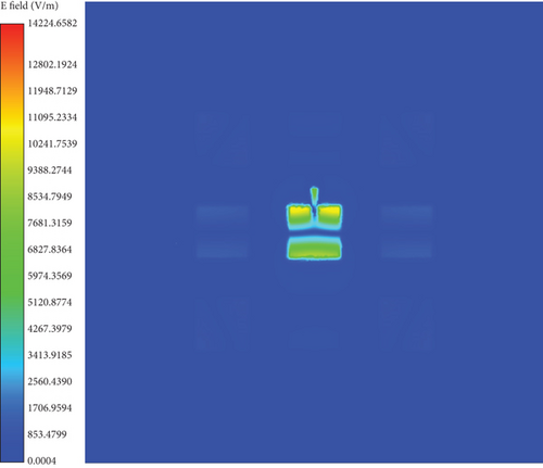
After completing the simulations, we first compared the electric field amplitude distribution at the center frequency, as illustrated in Figure 10. Subsequently, we compared the far-field antenna gains, with the results presented in Figure 11. It can be observed that the calculation results of the universal solver are consistent with those obtained using HFSS and CST. To further validate the accuracy of the universal solver, we performed a frequency sweep on the antenna element, ranging from 2 to 28.6 GHz. Figure 12 shows the comparison of S11 parameters calculated by all solvers over the sweep range. Despite larger errors at certain individual points due to differences in mesh quality, the overall results indicate that the universal array solver closely agrees with HFSS and CST. Based on our experience, such errors can be mitigated through further mesh refinement.

As detailed in Table 1, various metrics were recorded and compared for each solver during the computational process. These metrics included the number of parallel threads, mesh count, number of unknowns, solution method, memory consumption, and computation time. It is important to note that while performing calculations on the initially mentioned test machine, HFSS automatically switched to a direct method for simulation due to memory limitations. This occurred despite the solution options being set to the DDM. In contrast, the universal solver completed the calculations without any issues. Therefore, to better compare the computational efficiency of the DDM, both HFSS and the universal solver were subsequently deployed on a server equipped with an Intel Xeon CPU at 2.4 GHz, featuring 1024 GB of RAM and 76 cores.
| No. | Solver | Computing platform | Threads | Mesh | Subdomain number | Unknowns | Peak memory (GB) | Solution time (h:min:s) |
|---|---|---|---|---|---|---|---|---|
| 1 | HFSS-direct | 18 core-256 G | 18 | 3,213,254 | / | 20,465,049 | 210.6 | 06:41:26 |
| 2 | CST-domain | 18 core-256 G | 18 | 3,200,166 | 60 | / | 239.9 | 00:50:14 |
| 3 | Universal solver | 18 core-256 G | 18 | 3,253,315 | 150 | 21,298,340 | 71.7 | 00:42:34 |
| 4 | HFSS-DDM | 76 core-1024 G | 75 | 3,214,095 | 19 | 22,004,809 | 187.8 | 00:27:39 |
| 5 | Universal solver | 76 core-1024 G | 75 | 3,253,315 | 19 | 19,721,564 | 123.7 | 00:19:01 |
| 6 | Universal solver | 76 core-1024 G | 75 | 3,253,315 | 75 | 20,638,974 | 96.0 | 00:15:17 |
| 7 | Universal solver | 76 core-1024 G | 75 | 3,253,315 | 150 | 21,298,340 | 82.7 | 00:17:01 |
From Table 1, it is evident that the DDM significantly reduces both computation time and memory consumption compared to the direct method. Furthermore, the data in Cases No. 5, No. 6, and No. 7 indicate that peak memory consumption decreases as the number of subdomains increases. This reduction is due to the smaller dimensions of the subdomain matrices processed simultaneously. It is noteworthy that the simulation time initially decreases and then increases as the number of subdomains grows. This trend arises due to the impact of subdomain quantity on the convergence of the iterative process. As emphasized in the parallel iterative algorithm proposed in Section 3, the simulation tool’s parallelism depends on both the number of subdomains and the core count of the computing platform. Therefore, in Table 1, although 75 cores were assigned for Case No. 5, only 19 cores were actually utilized, corresponding to the 19 subdomains. Lastly, the table illustrates that the universal solver outperforms HFSS in terms of both computation time and memory consumption, demonstrating that the proposed algorithm significantly enhances computational efficiency. Additionally, a key advantage of the presented simulation tool is its flexibility in specifying the number of subdomains. Increasing the number of subdomains can reduce memory consumption to a certain extent and simultaneously improve parallelism during the iterative process.
5.2. Array Antenna With Radome
In this subsection, we use an array with a periodic structure to validate the simulation accuracy and efficiency of the periodic solver. The array chosen for simulation is an example from the HFSS case library [34]. As depicted in Figure 13, the array comprises a dielectric substrate, a dielectric radome, metal radiation patches, and a metal ground plane. Given its structural characteristics, the array can be partitioned into 25 regular subdomains. Among these, four are unique subdomains, while the remaining ones can be represented by those shown in Figure 14. It is crucial to note that the application positions of radiation boundaries vary across different subdomains. Consequently, the actual number of subdomains required for computation is nine.
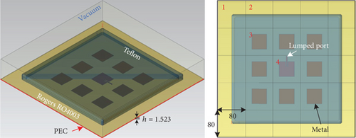

In this computation, the periodic solver utilizes a lumped port excitation, with the normalized impedance set to 50 Ω and a center frequency of 1.8 GHz. For comparison, the HFSS setup uses identical configurations. Specifically, the HFSS solver employs the 3D component array as the solution type and the DDM under the solution options. The adaptive meshing setting is disabled, and the maximum number of passes is set to 1, while other parameters remain at their default values. Additionally, to ensure a fair comparison, both solvers are configured to generate approximately the same number of mesh elements. Parallel processing is enabled in both solvers, with each utilizing 15 threads.
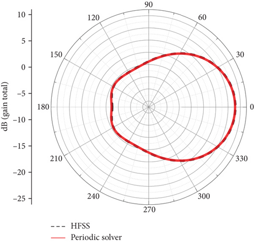
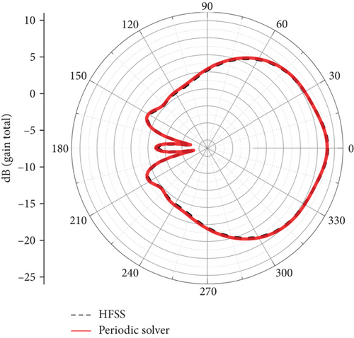
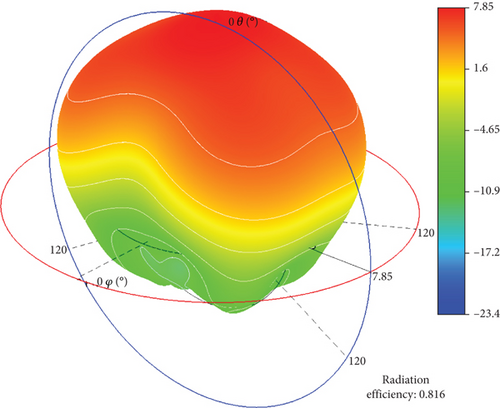
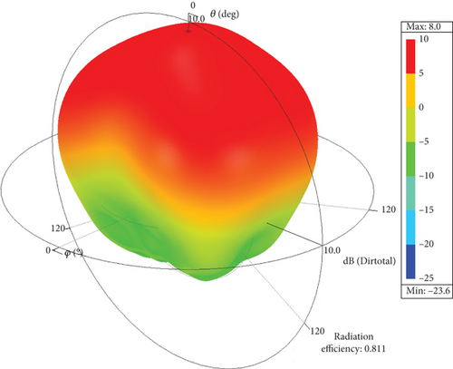
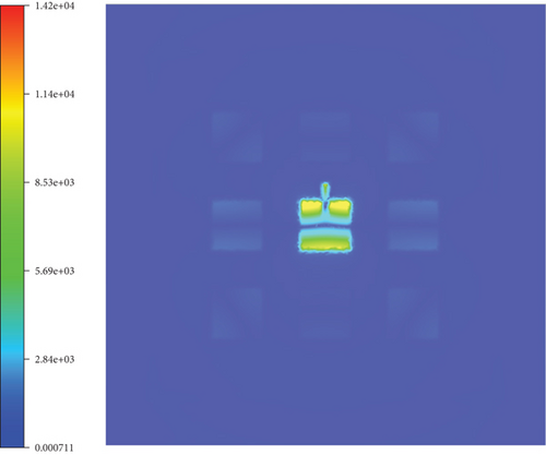
After completing the simulations, we first compared the antenna radiation patterns for far-field phi angles of 0° and 90°, as shown in Figure 15. Subsequently, we compared the 3D radiation patterns, with the results presented in Figure 16. Finally, we compared the electric field amplitude distribution at the center frequency, as illustrated in Figure 17. From these comparisons, it can be observed that the results obtained from the periodic array solver are consistent with those from HFSS. Additionally, Table 2 summarizes and compares the number of mesh elements, unknowns, peak memory consumption, and computation time used by both solvers. The data indicate that the periodic solver demonstrates a significant advantage in computational efficiency.
| Solver | Mesh | Subdomain number | Unknowns | Peak memory (GB) | Solution time (h:min:s) |
|---|---|---|---|---|---|
| HFSS | 1,464,902 | 25 | 9,619,657 | 52.0 | 00:08:38 |
| Periodic solver | 1,529,561 | 25 | 10,171,196 | 10.0 | 00:06:41 |
5.3. Vivaldi Array Antenna
Compared to the universal solver, the periodic solver offers significant advantages in array antenna simulations. First, the periodic solver does not require establishing the complete array model and boundary excitations. Second, since the subdomains of the periodic solver use nonmatching grids, they can be independently and freely meshed. This approach makes localized mesh refinement more convenient and results in a lower total number of meshes compared to the universal solver. Additionally, the periodic solver allows the array scale to be extended without remodeling, using 3D components for easy expansion. Finally, it substantially reduces peak memory requirements by retaining data only for the 3D component subdomain in memory.
To further validate the periodic solver’s capability in array antenna simulation, we conducted a simulation of a scalable array antenna excited by wave port. The array, which uses the Vivaldi element [35] as its 3D subdomain components, is illustrated in Figure 18. The dielectric plate has a relative permittivity of 2.2 and a thickness of 4 mm. The array operates at a frequency of 5.0 GHz. All wave ports are excited with a magnitude of 1 and a phase of 0. The 3D component array module and DDM in HFSS were utilized. Additionally, in CST, the solution type was set as domain, the computational domain was divided into 62 subdomains, and other settings remained the default. Parallel processing was enabled in all solvers, each utilizing 15 threads.
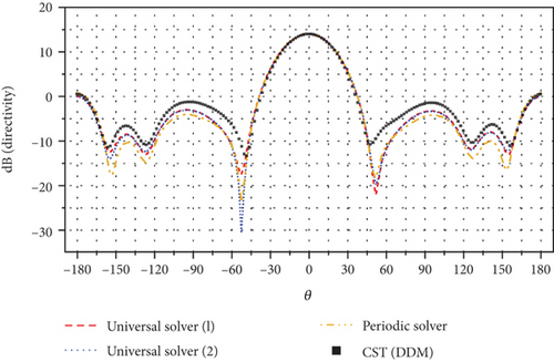
We initially simulated the 5 × 5 array using both the periodic solver and the universal solver. The universal solver employs two dissimilar meshes at the interface of subdomains: The Universal Solver (1) indicates that the problem region is partitioned by nonplanar meshes, while the Universal Solver (2) indicates that the problem region is partitioned by planar meshes. Figure 19 illustrates the consistency of the simulation results obtained using the universal solver and CST. Table 3 presents a statistical analysis of 5 × 5 Vivaldi antenna array simulations, demonstrating the tool’s exceptional simulation efficiency. The periodic solver demonstrates significant memory savings compared to the universal solver. Additionally, implementing planar meshes at the subdomain interface can enhance the convergence of the universal solver in periodic array simulations. Due to CST’s memory requirements exceeding the platform limits in subsequent simulations, we did not include its data statistics and comparisons beyond this point.
| Solvers | Subdomain interface mesh | Mesh | Unknowns | Peak memory (GB) | Iteration time (h:min:s) |
|---|---|---|---|---|---|
| CST domain | / | 664,101 | / | 57.9 | 0:05:58 |
| Universal solver (1) | Nonplanar mesh | 635,943 | 5,586,744 | 15.2 | 00:02:18 |
| Universal solver (2) | Planar mesh | 630,594 | 4,966,870 | 14.6 | 00:01:32 |
| Periodic solver | Planar mesh | 644,100 | 4,093,850 | 3.1 | 00:01:15 |
We then compared the antenna patterns calculated by both the tool and HFSS for the 25 × 25 and 50 × 50 Vivaldi arrays, as shown in Figures 20 and 21. The Periodic Solver (1) indicates that the block Gauss–Seidel–pMUS preconditioner is used, while the Periodic Solver (2) indicates that the parallel multilevel preconditioner proposed in this article is used. In both cases, the tool results agree favorably with the HFSS results over the entire angular spectrum.
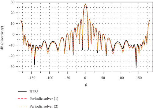

Table 4 tabulates some statistics for each simulation. When simulating the 25 × 25 array, the time consumption using the proposed preconditioner amounts to 37.8% of that observed in HFSS. When simulating the 50 × 50 array, the time consumption using the proposed preconditioner amounts to only 12.1% of that observed in HFSS. Notably, by comparing the data from Tables 2 and 4, we observe that HFSS appears to use a direct method for subdomain solutions in the example of Table 2, and we observe that HFSS appears to use a direct method for subdomain solutions in the example of Table 4. As a result, the peak memory usage in this calculation is less than that of the periodic solver. Furthermore, in the simulation of the first case, the time consumption of the proposed preconditioner accounts for 6.4% of that observed in the Periodic Solver (1). In the second case, the time consumption of the proposed preconditioner accounts for only 5.3% compared to that observed in the Periodic Solver (1).
| Size of array | Solver | Preconditioner | Mesh per block | Unknowns | Peak memory (GB) | Precondition time (s) | Iteration time (h:min:s) |
|---|---|---|---|---|---|---|---|
| 25 × 25 | HFSS | \ | 22,955 | 119,462,351 | 12.1 | \ | 00:41:49 |
| Periodic solver (1) | Block Gauss–Seidel + pMUS | 22,983 | 101,981,308 | 20.3 | 40 | 04:08:39 | |
| Periodic solver (2) | Proposed | 22,983 | 101,981,308 | 20.2 | 19 | 00:15:48 | |
| 50 × 50 | HFSS | \ | 22,955 | 442,713,476 | 40.5 | \ | 06:54:38 |
| Periodic solver (1) | Block Gauss–Seidel + pMUS | 22,983 | 385,040,408 | 71.4 | 40 | 15:47:03 | |
| Periodic solver (2) | Proposed | 22,983 | 385,040,408 | 71.3 | 18 | 00:50:12 | |
5.4. Array Antenna With Radome
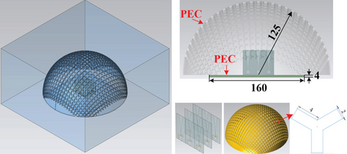
Although the periodic solver is more computationally efficient in array antenna simulations, it faces challenges when handling complex nonperiodic antenna structures. In contrast, the universal solver can automatically partition the complete model and generate the mesh for simulation, making it more versatile in terms of application scope. In this section, we use an array antenna with a frequency-selective surface radome on a metal platform as an example to validate the universal solver’s capability in simulating complex, large-scale antenna models. The complex antenna structure, shown in Figure 22, consists of a 3 × 3 Vivaldi antenna array similar to the one in the previous section, placed on a metal platform and covered by a metal frequency-selective surface radome. The arrays operated at a frequency of 5.0 GHz. Planar mesh partitioning with better convergence is adopted in the simulation. The antenna patterns calculated by both the tool and HFSS using default settings were compared in Figure 23, demonstrating a level of agreement with the reference HFSS. The Universal Solver (1) indicates that a parallel Jacobi preconditioner is used, and the subdomains employ the direct method for matrix inversion. The Universal Solver (2) indicates that the parallel multilevel preconditioner proposed in this article is used.
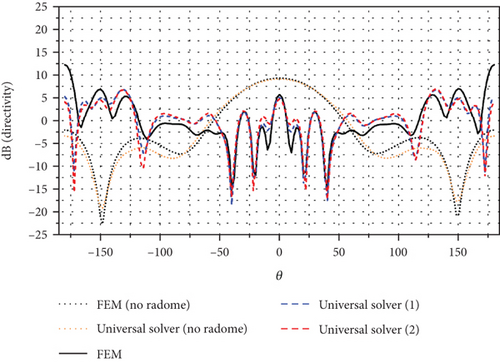
In Table 5, some of the statistics for each simulation are tabulated. As shown in Table 3, the Vivaldi arrays equipped with a radome involved approximately 50 million unknowns. However, the FEM solver failed to accurately simulate the array. The proposed preconditions require only 17.7% of the time consumption and 40% of the memory consumption compared to the Universal Solver (1).
| Solver | Preconditioner | Unknowns | Mesh | Peak memory (GB) | Iteration time (h:min:s) |
|---|---|---|---|---|---|
| Universal solver (1) | Jacobi + subdomain direct method | 47,625,182 | 6,466,499 | 246.4 | 02:11:11 |
| Universal solver (2) | Proposed | 54,996,066 | 6,466,499 | 91.1 | 00:23:14 |
6. Conclusion
In this work, we developed a fast electromagnetic radiation simulation tool for simulating periodic and universal array antennas. First, we conducted a comparative analysis of two distinct types of nonoverlapping DDMs that can be employed as preconditioners. Then, we utilized the block Jacobi preconditioner to enhance the computational efficiency of outer-loop matrix operations. To further improve the efficiency of inner-loop subdomain matrix inversion, we developed a multilevel preconditioner with the multifrontal block ICC method. This entire process can be executed concurrently within each subdomain. Based on the aforementioned theory, we developed a parallel multilevel preconditioner. Subsequently, we introduce two types of domain partitioning strategies. For a finite periodic array antenna, we obtained the subdomains corresponding to the repetitive array unit by transforming the same array unit rather than explicitly modeling it, aided by a GUI. Similarly, we derived the matrices of the remaining subdomains through manipulation of the matrix formed by the array unit, significantly reducing memory usage. Another attractive aspect of this method lies in its efficiency, as it requires only a minimal number of port excitations in the array simulation. When encountering a universal array, dividing the problem region by nonplanar meshes becomes more straightforward and convenient. The proposed preconditioner demonstrates superior efficiency compared to using a parallel Jacobi preconditioner that employs the direct method in subdomains. Finally, the simulation of Vivaldi antenna arrays and arrays with radome demonstrate that the proposed tool exhibits satisfactory concurrence with the FEM in terms of accuracy. Particularly, the tool exhibits a notable decrease in time consumption compared to HFSS and CST when simulating finite periodic arrays.
The large-scale array antennas and platform-mounted array antennas used in current fields such as mobile communications and medical imaging have complex structures. In addition to features like holes, slots, and curved surfaces, they also feature multiple layers and various media types. On computational platforms with small to medium-scale hardware, conventional methods and software often cannot achieve accurate and efficient simulations of these large-scale, multiscale problems. The example presented in this paper includes characteristics such as thin-layer media, multiple materials, hole structures, and large scale. Therefore, the simulation tool demonstrated has broad application prospects in such fields. In the future, we will further enhance the tool’s simulation efficiency by integrating mesh adaptive techniques.
Conflicts of Interest
The authors declare no conflicts of interest.
Funding
This work was supported by the National Natural Science Foundation of China (Grant Numbers 62071102 and 61921002).
Open Research
Data Availability Statement
The data that support the findings of this study are available from the corresponding author upon reasonable request.


