A Novel Design and Implementation of a Surface Sediment Sampling Robot
Abstract
This research presents the design and development of a robot for the collection of surface aquatic sediments in shallow water environments. The robot’s primary function is to enhance traditional sampling techniques and ensure precise data for environmental assessment. The robot’s working principle involves being manually placed at the sampling point, where it descends under its own weight through the water column until reaching the sediment bed. At this point, it employs an innovative drilling system that combines rotational and linear movements, enabling a conical-shaped collector to gather samples from the uppermost 52 mm of sediment while minimizing the loss of fine sediment. Primarily constructed with 3D-printed parts, the robot features a modular layered design in its mechanical structure, facilitating both assembly and maintenance. The control system is composed of a Raspberry Pi (RPI), a stepper motor driver, an H-bridge, and optical sensors for position and velocity feedback. Additionally, a monitoring system was implemented through a local Wi-Fi network to visualize drilled distance, linear velocity, angular velocity, and battery voltage during the sampling process. Multiple tests have been carried out in the laboratory, where the amount of sediment collected ranged from 84.2 to 151 g depending on the sampling duration, demonstrating the robot’s capability and consistency in meeting standard requirements.
1. Introduction
Pollution is a problem that affects ecosystems and the organisms that live in them. This problem has been increasing in recent years due mainly to anthropogenic sources, such as industry and growing cities [1, 2]. These pollutants are harmful to the ecosystem because they end up in estuaries or coastal waterways, creating a potential risk for biota [3]. Various investigations around the world have studied the level of contamination by heavy metals [4–7] and microplastics [8, 9], evidencing a problem coming from various sources of contamination and in different aquatic environments such as rivers, lakes, oceans, or reservoirs.
The previously mentioned investigations used the analysis of surface sediments as a method to identify the contaminants present in the ecosystem. The surface sediments, representing the uppermost 2–3 cm of the bottom sediment layer, have the capacity to absorb or retain hydrophobic chemical contaminants, allowing, through their collection and analysis, to obtain information on the possible contaminants present in the environment, and that could pose a risk to the ecosystem [10].
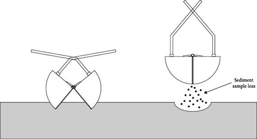
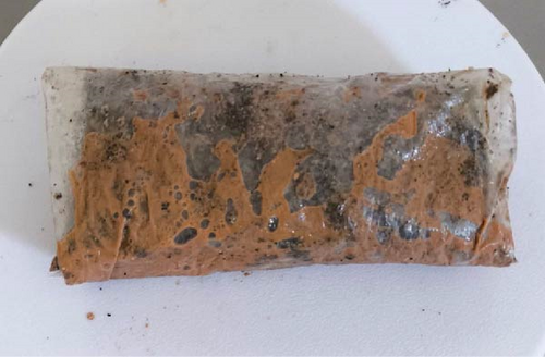
Most sediment collectors can be used for surface sediment collection; however, they have some limitations. For example, in manual sampling with shovels, trowels, or spoons, water flow direction and strength must be considered to minimize the loss of fine sediment [3]. On the other hand, grab samplers may suffer from sealing issues due to wear or the presence of solid particles, potentially leading to sample loss [11], as seen in Figure 1. A similar issue occurs with core samplers, which are limited to a certain grain size, causing the loss of finer sediment. In those cases, sediment loss during tool elevation results in the release of fine particles and contaminants from the sample into the surrounding water, leading to an underestimation of the finer particles in the sample [12].
The implementation of robotic devices for sediment sample collection offers significant potential to enhance the efficiency of the sampling process through automation. Previous research has explored a variety of innovative designs and configurations to address this challenge. For instance, one study developed a remotely operated vehicle (ROV) equipped with an adjustable buoyancy system and an optimized sampling core, enabling the robot to submerge and insert the collector to retrieve sediment samples [13]. Another approach combined two robots: a ground vehicle designed to extract and transport sediment using an aluminum tube with a wedge to minimize sample loss, and an aerial drone tasked with capturing images to assist operators in defining sampling routes and objectives [14]. Researchers have also tested a robotic system that integrates linear and rotational motion to penetrate the sediment, employing a perforated tube design, although this design still presents opportunities for improvement [15]. Furthermore, a lightweight and portable ROV powered by dual thrusters has been employed to provide the vertical force necessary for sediment penetration, with additional experiments evaluating the maximum penetration depth achievable using this thruster system together with a core collector featuring helical fins [16, 17]. In addition, an underwater robot with articulated limbs and a claw-type grabbing mechanism has been developed to collect marine sediment samples specifically aimed at microplastic analysis [18]. Complementing these hardware advancements, further studies have focused on optimizing the movement patterns of sediment collection robots, enhancing sampling efficiency across different sediment types through the use of core samplers [19].
Despite the advances in automation mentioned earlier, most current robotic collectors still rely on traditional sampling tools, such as corers and grabs, and therefore continue to face issues related to the loss of fine particles. Although these tools have undergone certain optimizations, there remains room for improvement in the design of the sampler tip to enhance material retention during collection.
- •
For heavy metal and metalloid analysis, the sample weight must be at least 50 g [20], while for microplastic analysis, a sample of more than 25 g is required [21].
- •
In both types of analysis, sediments must be extracted from the first few centimeters of depth, as this is the layer with the highest concentration of these elements.
- •
The loss of fine sediments, which are crucial for an accurate quantification of contaminants, must be minimized.
Unlike stratigraphic studies, where structural integrity is important, in microplastics analyses, sample disturbance is less critical, as laboratory protocols involve sieving and chemical treatment processes for particle separation [21], a methodology that also applies to metal analysis [22].
This article presents the design and development of an innovative robotic mechanism for collecting surface sediment by combining rotational and linear motion, along with a conical-shaped collecting tip featuring helical fins. The main function of the robot is to obtain a valid sample for the analysis of heavy metals and microplastics, providing the advantage of minimal loss of fine sediment due to the shape of the collecting tip. In addition, a real-time monitoring system utilizing a local Wi-Fi network is implemented to observe and analyze drilled distance, linear velocity, angular velocity, and battery voltage.
To validate the prototype, a controlled environment was prepared using a container to simulate shallow water and sediment conditions. Different tests were carried out with varying collection times, allowing for the validation of the prototype’s performance and the consistency of the collected mass in each test.
2. Materials and Methods
2.1. Working Principle
- •
Rotational movement: Generated by the DC motor, which, due to the geometry of the collecting tip, facilitates efficient drilling through sedimentary material.
- •
Linear movement: Generated by the stepper motor, through a threaded rod that converts the rotational movement into linear, allowing the insertion of the collecting tip into the sediment.
These combined movements ensure that the collector penetrates the sediment effectively, reaching the necessary depth to favor the entry of the sediment into the interior of the tip. Figure 2 shows the principle of operation of the robot.
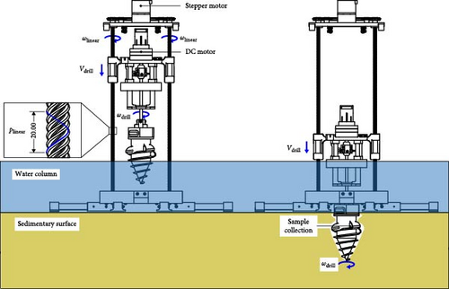
Figure 2 shows the main magnitudes that describe the operation of the system. First, two angular velocities are observed: ωdrill, which is the speed generated by the DC motor and is applied directly to the collection tip; and ωlinear, which is generated by the stepper motor and transformed into the drilling linear speed Vdrill through two threaded rods. In addition, the pitch distance of the threaded rods, referred to as plinear, is observed to be 20 mm.
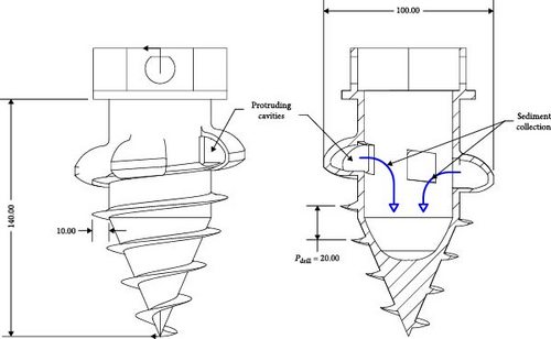
The collection tip is the component designed to penetrate the sediment for the purpose of sample acquisition. It features a conical tip and helical fins surrounding it, which enhance its drilling capacity by disrupting and displacing the sediment as it progresses. The sediment enters through side holes in the collector, which prevents the loss of fine sediment once the sediment is collected. This piece was designed based on the model shown in [15], adding the following modifications: The addition of four protruding cavities with a concave shape on the sides of the end of the travel of the helicoid with the purpose of guiding the sediment into the collector by action of rotation and the addition of a conical tip surrounded by helices to reduce tip resistance upon entering the sediment. The main parameters of the tip design are shown in Figure 3, where a helicoid pitch distance pdrill of 20 mm is shown, along with the protruding cavities through which the sediment enters.
Certainly, the use of plastics harms the environment, particularly when they are employed as tools for microplastic contamination analysis. In the present study, the sediment collector has been fabricated with polylactic acid filament (PLA) using a 3D printer. This was done only for validation purposes in a controlled environment before being scaled to real-world applications using more sustainable materials.
Therefore, by taking the nominal speed of the DC motor ωdrill = 0.5 rev/s, the stepper motor must generate a speed of ωlinear = 0.5 rev/s in order to synchronize the linear and angular drilling speeds (Vdrill and ωdrill).
2.2. Mechanical Design
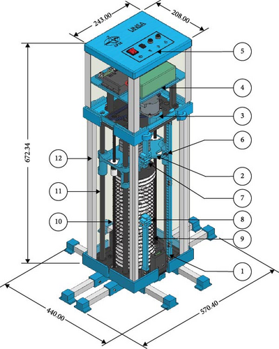
Most of the parts were 3D printed using PLA, enabling the design of custom components specifically adapted to facilitate the assembly of all electrical and mechanical parts. The robot’s design was structured in layers, following a modular approach where each layer serves a specific function, as illustrated in Figure 4. Additionally, some supplementary elements are also shown, such as optical upper and lower limit sensors that allow linear movement to be delimited and the linear encoder that measures the vertical distance traveled by the collector Ddrill and its speed Vdrill.
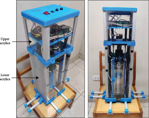
Since the robot is tested in a controlled laboratory environment with shallow water, a basic sealing system was implemented to protect the robot’s components without making it fully submersible. Transparent acrylics were used on the sides to shield both the mobile layer (lower acrylics) and the circuit layer (upper acrylics), as shown in Figure 5. Additionally, an isolation spring was installed between the base and the movable layer to allow vertical movement of the collecting tip while maintaining the system’s seal.
2.2.1. Base
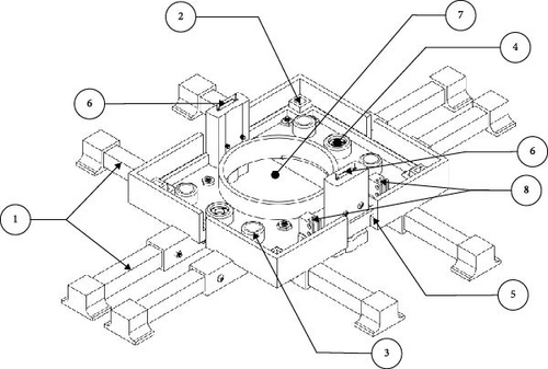
The base is the part located at the bottom of the robot, its main function is to provide the robot with greater robustness and resistance to overturning, which can be caused by drilling the sediment. To achieve this, transverse aluminum square rods were attached to the bottom of the base, thus increasing the area in contact with the sediment and therefore the stability of the robot. In addition, the base was designed to support structural elements that were assembled with the rest of the robot, which are four vertical square rods, two smooth rods, two threaded screws (coupled to bearings), and the side upper and lower acrylics.
Since this component is the first to make contact with the sedimentary surface, a bottom detection system was implemented using two magnetic switches (bottom detection sensors). These sensors are activated when a mobile piece, attached to a magnet located at the bottom, triggers them as the robot reaches the sedimentary surface. The activation sends an electrical signal, which is used to start the collection process.
Figure 6 shows the CAD model of the base with its main parts.
2.2.2. Mobile Layer
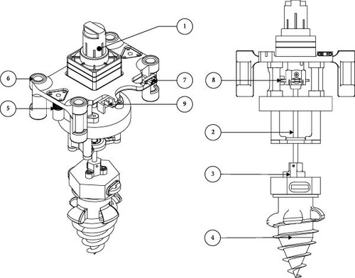
The mobile layer is the component that moves vertically during the collection process, its main function is to support the DC motor and the collection tip coupled to its shaft. To provide linear movement, this piece is subject to 2 spindle, which move by the action of the rotation of the threaded screws coming from the stepper motor.
As seen in Figure 7, this layer is equipped with two sensors: one coupled to a perforated strip, so that it acts as a linear encoder, which allows the measurement of the vertical distance drilled and the linear speed; and a rotational encoder, located in the initial part of the DC motor shaft. Also located in this layer is an activation tab that is detected by the upper and lower limit optical sensors, indicating the end of the vertical travel of the mobile layer.
2.2.3. Gear Layer
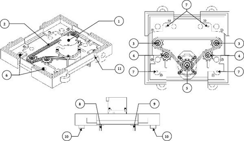
In the gear layer (Figure 8) there is mainly a 3D printed platform that acts as a base for the rest of the components. On this piece there is a stepper motor connected to 5 sprockets that, through a chain, transmit the movement to the threaded screws, allowing the vertical movement of the mobile layer. Of the five sprockets, one is connected directly to the motor shaft, two are used to tension the drive chain, and two are attached directly to the threaded screws. The piece has four screw holes for mounting the control box supports, which are installed on top. Additionally, the sides of the piece include supports for the upper acrylics.
2.2.4. Control Box and Top Layer
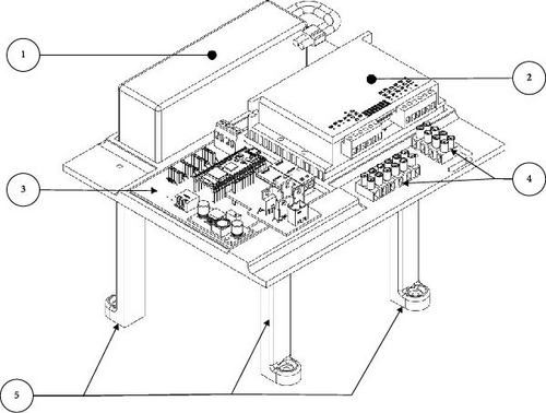
The control box is the part where the control and power circuits of the robot are assembled. The main parts are: 22.2V battery, stepper motor driver, main control board, H-bridge and connection terminal blocks. The piece was designed to integrate and centralize all the circuits in the available space. These elements are seen in Figure 9a.
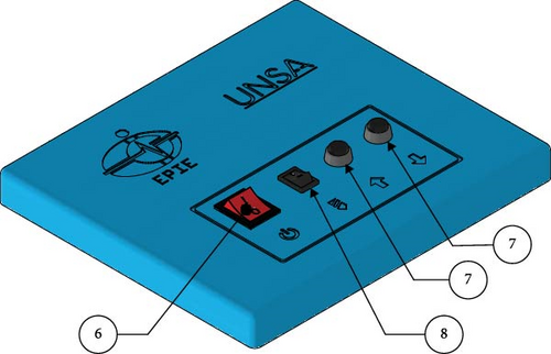
Finally, on the top of the robot is the cover (Figure 9b) whose main function is to mount the control switches of the robot and provide sufficient waterproofing to protect the robot during the sampling process. For waterproofing, a strip of waterproof foam was used glued around the edge of the lid, so that when the acrylic enters, a pressure-tight seal is generated. This system ensures splash protection that protects the control circuits.
The control knobs are made up of four controls: 1 general system on/off switch, 1 automatic/manual mode control switch, 2 up and down buttons for manual control of the robot. These were sealed with waterproof glue on the back to prevent water ingress.
2.3. Electrical Design
2.3.1. Main Control System
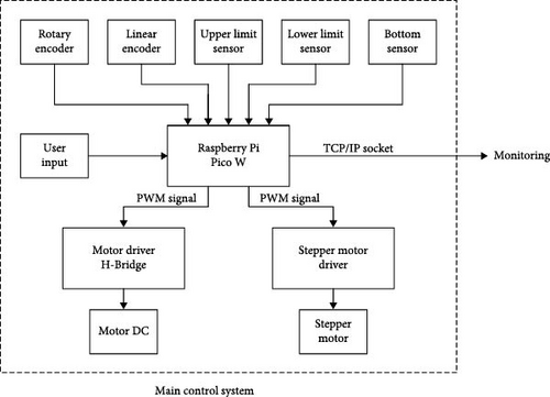
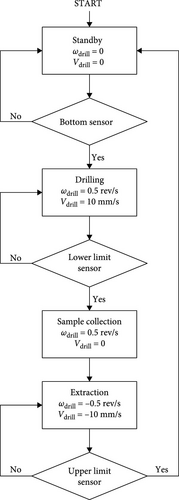
The control architecture is described in Figure 10a. The microcontroller unit (MCU) used is the Raspberry Pi (RPI) Pico W, which receives and processes the signals from all the sensors, and sends the pulse width modulation (PWM) signals to the motor controllers following the collection sequence. The main sensors used for the state transition are: the bottom detection sensor, which detects when the prototype has reached the sedimentary bottom, and the upper and lower limit sensors, which maintain the position of the mobile layer within the limits. Additionally, two optical sensors were implemented that act as linear and rotational encoders to measure angular velocity, linear velocity, and drilled distance. The main MCU program must follow the sequence shown in Figure 10b, where four states are defined:
- 1.
Standby state: The robot is ready to operate and is waiting for it to descend to the sedimentary bottom to start collecting. The signal from the bottom detection sensor is needed to transition to the next state.
- 2.
Drilling state: The DC motor and the stepper motor are activated, the mobile layer with the collecting tip begins to descend and drill the sediment until it reaches the collection limit delimited by the lower limit sensor. At this moment the next state is initiated.
- 3.
Collection state: Once the lower point is reached, the stepper motor is deactivated to stop the linear movement while the DC motor maintains the rotation of the collector in order to collect the greatest amount of sediment. This state is maintained for a configured time.
- 4.
Finally, the extraction of the collecting tip begins by activating both motors again, but in the opposite direction. This minimizes the effort required to extract the tip, preventing the helicoids from acting as a fixation system that anchors the tip to the sediment during its removal. The tip is retracted to its initial position, and once the upper limit is reached, both motors stop and return to the standby state.
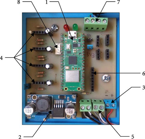
2.3.2. Control Board Design
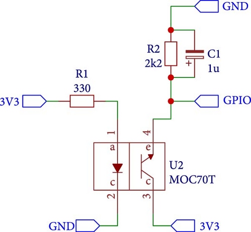
To control the robot, a main board was designed (Figure 11a) where the MCU, sensor connections and control knobs are centralized. In addition, this board contains the connections for the PWM output signals to the respective controllers of each motor. For the connection of the bottom magnetic sensors and the control switches, an internal pull-up configuration of the MCU was used so that the connection of these switches is direct to the general-purpose input/output pin (GPIO) of the MCU. For the battery measure, a voltage divider was used to reduce the battery voltage to levels within the range of the analog-to-digital converter (ADC). For the connection of the upper and lower limit optical sensors and encoders, the configuration shown in Figure 11b was used, where the infrared LED is polarized with a voltage of 3.3 V and a resistance of 330 Ω, while the output transistor is supplied with 3.3V on the collector. The signal is extracted in parallel to resistor R2 and capacitor C1 at the emitter pin.
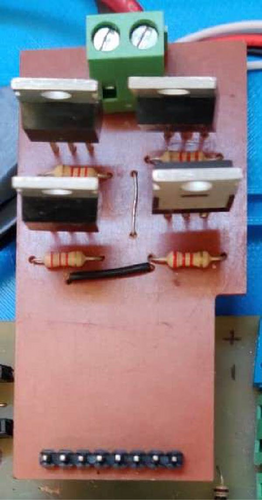
To control the DC motor, an H-bridge was designed (Figure 11c) so that it fits on the main board as a removable module. A typical configuration was used with two P-channel (IRF9540) and two N-channel (IRF540) mosfets, which are driven by the output pins of the MCU through PC817 optocouplers.
2.4. Monitoring
The use of the RPI Pico W board allows the implementation of a wireless monitoring system using a local Wi-Fi network. The topology is shown in Figure 12 where it is observed: An access point as a central element, which allows multipoint connectivity between devices on the local network; a socket server that receives and stores the data coming from the robot, and which also acts as an HTTP server where the web page that shows the data to the clients is hosted; and the collector robot that obtains and sends the data as a client through sockets.
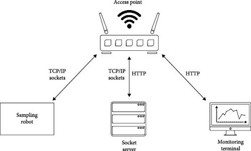
A basic configuration of the network was carried out to guarantee its operation, which consists of assigning static IP addresses to the collector and the server, excluding these addresses from the DHCP pool of the access point, serving as the DHCP server for the network, and establishing a name and password for the network SSID. This configuration ensures that there are no repeated IP when clients connect to the network.
- •
From the collector side: Every time the collector sends a message, the server must respond with an “ACK,” indicating to the collector that the connection is working. If the collector does not receive a confirmation message after sending N messages (where N is a software-configurable number), the socket closes and attempts to reconnect with the server.
- •
From the server side: A timeout was configured that represents the maximum interval without receiving messages from the collector. If it times out, the server closes the socket and re-enters listening mode to accept new connections.
2.5. Experimental Setup
To test the operation of the prototype, a controlled laboratory environment was established, including a transparent container filled with sufficient sediment and water to simulate a real shallow-water environment, as shown in Figure 13. A fine sediment layer of clay was added to the surface, while the deeper sediment layer consisted of a mixture of fine and medium sand. Since clay is easily distinguishable by its color, it can be clearly identified from the rest of the sample.
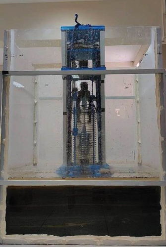
Additionally, a manual pulley system was installed overhead only for laboratory testing purposes, allowing manual control of the prototype’s descent to the sedimentary bottom.
- •
H-bridge pulse width of 100% to obtain angular velocity ωdrill = 0.5 rev/s (rated DC motor speed at 24 V)
- •
Pulse frequency for the stepper motor: Using the value ωlinear = 0.5 rev/s calculated in Equation (2), and taking the value of the stepper motor driver configured to operate at 400 pulses per revolution, the conversion was made obtaining a pulse frequency of 200 Hz.
- •
The time in the collection state was varied to determine the influence of collection duration on the total amount of sediment. The tests were conducted with four different collection state times: one with no collection state (0 s), and others with 5, 10, and 15 s. This allowed for the evaluation of the consistency of the mass collected by the prototype for each collection time.
Before submerging the robot, having already configured the program with the previously mentioned parameters, the network elements were prepared to start real-time monitoring, which are the access point and the socket server. When the robot was turned on, the connection status and data reception were checked to start the collection.
For each test, the robot was configured in automatic mode using the switch to put it in a standby state, and it was submerged in the sediment. The collection sequence began as established and at the end of the sequence, the robot was removed to extract the collected sample. For this, the robot was put in manual mode, and the mobile layer was lowered using the control knobs. Once down, the collecting tip was removed and the collected sediment was weighed.
Regarding the measured drilling distance, it does not represent the depth drilled into the sediment, as the collecting tip is offset from the sedimentary surface, starting at an initial position 90 mm above the surface (Figure 14). Therefore, to determine the effective drilling distance, the initial offset of the collector (90 mm) is subtracted from the total drilled distance (230 mm), resulting in an effective drilling distance of ~140 mm.
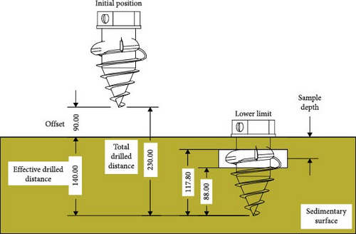
To estimate the depth of the collected sediment, refer to Figure 14. This figure shows that the drilling distance required for sediment to enter the collector through the holes in the collecting tip ranges from 88 to 117.8 mm. By subtracting this range from the effective drilling distance (140 mm), the approximate depth of the collected sediment is calculated, resulting in a sample depth range of 22.2 to 52 mm.
3. Results and Discussion
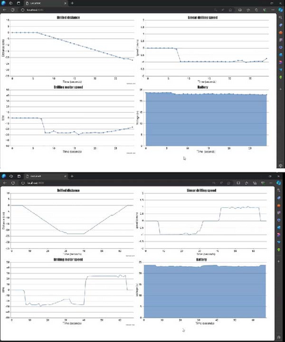
After completing the initial setup sequence described in the previous section, the prototype was tested in a controlled environment. Regarding data communication and visualization, real-time graphs of drilled distance, linear velocity, angular velocity, and battery voltage were displayed through a web browser, as shown in Figure 15. Additionally, the collected data from each test was stored for further analysis.
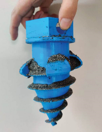
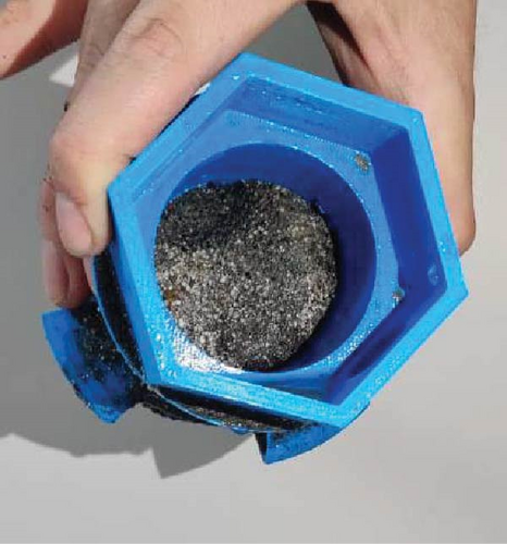
Furthermore, after each test, upon removing the collection tip from the mechanism, sediment accumulated during the sequence was observed on the tip (Figure 16), In particular, Figure 16c shows the presence of clay in the collected sample, demonstrating the mechanism’s ability to capture finer particles.
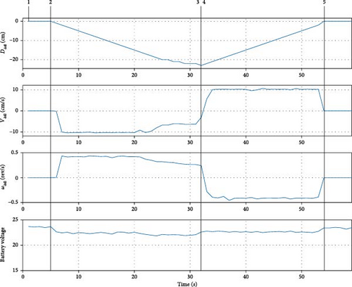
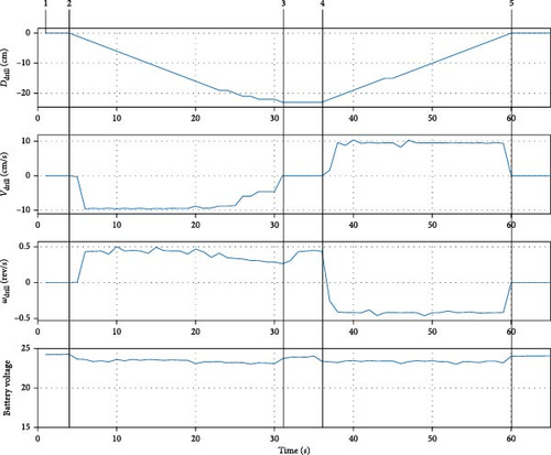
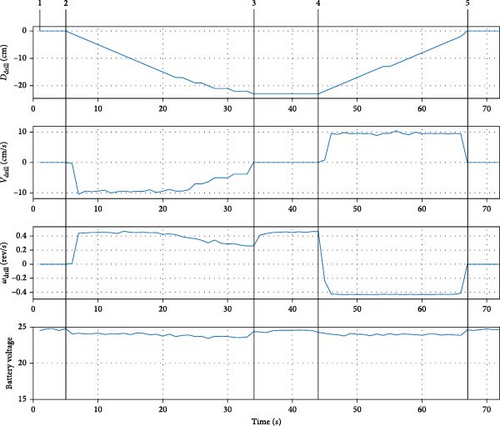
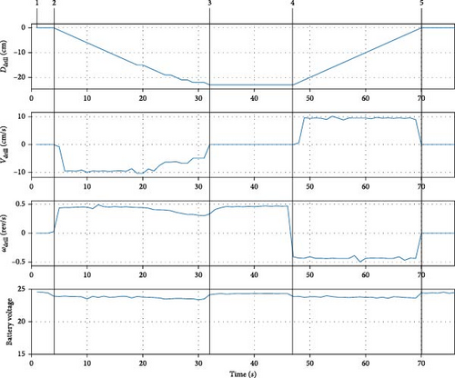
After conducting the collection tests, with varying collection state durations as established, the results for each collection time (0, 5, 10, and 15 s) are shown in Figures 17–20. These figures display the progression of each measured variable throughout the collection sequence.
- •
Point 1: Both motors are off, and the collector is on standby state, waiting to reach the bottom.
- •
Point 2: The drilling state begins, it is observed that the drilled distance begins to decrease, in addition, the linear speed Vdrill remains at ~10 mm/s, the drilling angular speed ωdrill at ~0.5 rev/s, according to what was previously calculated. In the 21st second, when the drilled distance indicates –14 cm, both the linear and rotational speeds begin to decrease due to the resistance of the drilled sediment. In addition, it was observed that the robot began to lose stability, however, the base was able to support the structure and prevent it from overturning.
- •
Point 3: When the drilling distance reached –23 cm, the lower limit of the linear path is reached and the collecting state begins. The linear motion stops, and the angular velocity returns to its initial nominal value while the collection state runs for the configured duration in each test.
- •
Point 4: Start the extraction state. The linear and rotational speeds are activated with their nominal values, but in the opposite direction, being Vdrill = − 10 mm/s and ωdrill = − 0.5 rev/s approximately. The drilled distance begins to increase indicating the rise of the mobile layer. Upon reaching point 5, the sequence returns to initial standby state.
After each test conducted with different collection times, the collected samples were weighed to determine the influence of collection duration on the amount of sediment gathered, as shown in Figure 21. It was observed that with no collection state (0 s), the amount of sediment collected was significantly low, with an average of 84.2 g. In contrast, the difference in mass collected at 5, 10, and 15 s showed no significant variation, with average masses of 139.3, 151, and 149 g, respectively.
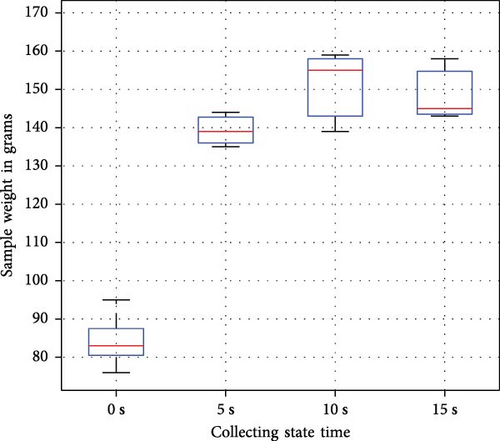
Although a slight increase in sediment mass was observed when the collection time was extended from 5 to 10 s, increasing the time from 10 to 15 s did not produce the same effect. It was observed that extending the collection time beyond 10 s did not improve the amount of sediment gathered, indicating that the maximum capacity of the collection tip was reached. Furthermore, the low variability within each time group highlights the prototype’s consistency in sample mass collected.
4. Conclusions
A surface sediment collection robot for shallow waters was designed and implemented, assembled mainly with 3D printed parts. The results of the tests conducted with varying collection times indicate that the maximum capacity of the collection tip is reached at 10 s. At 0 s of collection state, the amount of sediment gathered was significantly low, with an average of 84.2 g. As the collection time increased to 5 s, the sediment mass increased to an average of 139.3 g. Further increases in collection time showed a smaller difference, as the average masses at 10 and 15 s were 151 and 149 g, respectively. This suggests that extending the collection time beyond 10 s does not lead to a meaningful increase in sample volume.
Additionally, the low variability in the collected masses within each time group indicates that the collection mechanism, based on a linear and rotational movement for drilling the sediment, using a conical-shaped collection tip with helical fins, works effective, and consistently. This result demonstrates the system’s ability to meet the basic sample collection requirements in sediment pollution studies.
The monitoring system integrated into the robot worked successfully, providing reliable and consistent data during the tests, which were used for subsequent analysis of the collection process. This system has the potential to be applied in future research, offering a valuable tool for monitoring and analyzing environmental conditions in real time.
The waterproofing implemented in the robot was designed for controlled environments, where there are no adverse conditions such as water currents or high depths. For use in real environments, it is essential to design a more robust and hermetic system that guarantees the protection of internal components against the entry of water and contaminants. The improvement in waterproofing is crucial to ensure the longevity and reliability of the robot in practical applications.
Conflicts of Interest
The authors declare no conflicts of interest.
Funding
This research was funded by Universidad Nacional de San Agustin de Arequipa, through competitive funds (IBA-IB-69-2020).
Acknowledgments
This research was supported by Universidad Nacional de San Agustin de Arequipa, through the funding granted and the academic resources provided.
Open Research
Data Availability Statement
The data that support the findings of this study are available from the corresponding author upon reasonable request.


