Mechanical Characterization of Nano-SiO₂-Reinforced Epoxy Sandwich Composites With 3D Rayon Graphite Felt Core and Woven Carbon Fiber Face Sheets
Abstract
New epoxy (EP)-based sandwich composites have enhanced mechanical performance and optimized cost-effectiveness, as a result of composites’ increasing popularity. This study aims to develop composites with 3, 5, and 7 layers of woven carbon fibers (WCFs) layered on 3D rayon-based graphite felt (3D RGF) as the core of the sandwich composites. Using WCFs as face sheet layers increases flexural strength and modulus. Flexural strength increases to 226.92 MPa, and modulus increases to 15.18 GPa with 3 WCFs layers. Five layers increase modulus to 25.43 GPa and flexural strength to 370.21 MPa. Seven layers provide the highest modulus of 31.38 GPa and flexural strength of 405.07 MPa. Diverse concentrations of nanosilica (0.01, 0.1, 0.5, and 0.8 wt%) were embedded within the core to bolster its mechanical properties. Using an in situ casting method, an EP resin solution was infused into the structure, forming a bicontinuous composite. This method significantly enhances the toughness and adhesion between the fibers and the EP resin, resulting in superior mechanical properties. EP alone has 57-MPa tensile strength, but three layers of WCFs increase it to 531.38 MPa, five layers increase it to 647.24 MPa, and seven layers increase it to 764.40 MPa. The minimum tensile modulus of EP is 2.75 ± 0.5 GPa. The modulus increases significantly when layers of WCFs are added, reaching 9.75 GPa with three layers, 14.96 GPa with five layers, and a maximum value of 23.44 GPa with seven layers. When a little amount of nanosilica was added, the flexural properties of composites were significantly affected. Among all concentrations, 0. 5 wt% nano-SiO2 yielded the highest enhancement of flexural strength and modulus. At 0.1 wt% nanosilica, the flexural strength and modulus of the sandwich composites increase to 493.5 MPa and 30.5 GPa (23.4% and 24.5%). The peak occurs at 0.5 wt%, reaching 645.7 MPa and 41.5 GPa (61.4% and 69.4%). However, at 0.8 wt%, values drop to 560.1 MPa and 30.4 GPa, still showing 40.0% and 24.1% improvements. This study provides a new solution for reinforcing the mechanical properties of EP sandwich composites. Increasing the performance with nanofiller concentrations is also emphasized.
1. Introduction
A lightweight core of honeycomb or carbon fiber is sandwiched between two thin but stiff face sheets of metal or carbon fiber to form a sandwich composite [1, 2]. These composites may prove useful in the aerospace, automobile, marine, and construction industries since they are light yet strong, as provided by the structure of the composite. To improve fuel economy, performance, and sustainability in contemporary engineering projects, engineers are increasingly turning to sandwich composites, which enable substantial weight reduction without sacrificing structural integrity. In addition to reducing the total weight and material costs, using core material in the face sheets reduces the number of woven layers required, making sandwich composites a cost-effective alternative for high-performance applications [1, 2]. Common core materials include honeycomb and foam though new core structures are being developed to enhance the mechanical and impact properties of sandwich composites. Additionally, short fibers uniformly dispersed within epoxy (EP) composites can offer high mechanical qualities at a lower cost [3, 4]. To improve mechanical performance while reducing costs, an effective product option is to use composites with short fiber-reinforced foam as the core material and woven fibers as the face sheets. Utilizing sandwich composites with short fiber-reinforced foam as the core material and woven fiber face sheets is an efficient use of this technology. Hence, an effective product solution is to apply short fiber-reinforced polymer as the core of sandwich composites and woven fibers as the face layers in composites, as this can result in mechanical enhancement at lower costs. One of the most appropriate uses of this fiber reinforcement technology is in sandwich composites that incorporate short fiber-reinforced EP as the core structure with woven fiber face laminates. This layout effectively takes advantage of the lightweight and high-strength characteristics of the core structure, and the woven fibers that are aligned over the core greatly enhance the core’s strength [5]. This hybrid composite structure enables manufacturers to attain desired performance levels without the high prices of typical high-strength composites, offering a compelling alternative for sectors wanting to improve performance while limiting costs.
Graphite felt made from rayon is an advanced kind of carbon felt that has several useful industrial uses due to its excellent electrical and thermal characteristics [6]. It is produced by carbonizing and graphitizing rayon, a regenerated cellulose fabric, at temperatures higher than 2000°C [6]. This method produces a graphite-like material with textile fiber pliability. Due to its low thermal conductivity, excellent thermal insulation, and durability at high temperatures, rayon-based graphite felt (RGF) is ideal for heat-resistant applications [7, 8]. It also demonstrates excellent chemical resistance, particularly against acids and organic solvents, and maintains its structural integrity even under severe conditions [9]. The graphite felt keeps its shape even when subjected to extreme heat or cold, and it is very resistant to chemicals, especially organic solvents and acids [10]. The mechanical performance capabilities of graphite felt/EP composites are being enhanced by the use of RGF, which has outstanding thermal and chemical properties. Here, its structural properties are put to use to boost the mechanical strength of composites as a whole. The felt’s high tensile strength enhances its rigidity and load-bearing capabilities, while its porosity makes it adhere well to EP resins. This, in turn, ensures that stresses are distributed appropriately and lowers the possibility of fractures caused by mechanical stresses. Carbon felt is great for impact-resistant composites because of its energy absorption and dispersion [2].
By improving the mechanical characteristics and structural integrity of sandwich EP composites, which use woven carbon fibers (WCFs) as a face sheet and 3D network short-fiber-reinforced EP composites as a core, several performance-related issues with composite materials are efficiently addressed. Composite polymers made with this hybrid design have several benefits over those made with either woven carbon felt or carbon felt based on 3D networks of short fibers. Woven fiber face sheets increase composite structure rigidity and stiffness, making them ideal for aerospace and automotive applications [11, 12]. Three-dimensional network foam EP composites are noted for their isotropic properties, low cost, multidirectional strength, and energy absorption [8, 13, 14]. This combination takes advantage of the strengths of both materials, with the woven layer adding strength and integrity to the surface and the 3D network improving properties in multiple directions and interlaminar bonding [15]. According to Nabil et al. [2], woven fibers were used as a face sheet, and three-dimensional short carbon felt foam were used as a core to make sandwich EP composites. This hybrid technique creates a composite material that is stronger, longer lasting, and more versatile, making it perfect for high-performance applications.
EPs with carbon fiber-reinforced polymers that incorporate nanoparticles can be significantly enhanced in performance by casting epoxy with WCFs. The composite benefits from the addition of various nanomaterials, such as carbon nanotubes (CNTs) [16], graphene [17, 18], nanosilica [19], nanoclays [20], and polysulfone [21]. One main way these nanomaterials boost mechanical performance is by making the matrix more efficient in transferring loads and distributing stresses. The WCFs serve as the primary structural reinforcement, while the nanomaterial-infused EP matrix works at the nanoscale to optimize the composite’s mechanical properties. Together, they produce a high-performance composite material that is well suited for applications requiring superior mechanical strength, durability, and reliability. In addition, there are several advantages to using sandwich composites that have their tensile and flexural strengths increased by layering. The structural component’s load-bearing capability is enhanced by increased load transmission, which in turn reduces local failure. This effect results in improved composite structure strength, as more forces are mobilized before the ultimate damage occurs. Second, any additional layer helps in the integration of more stiffness and therefore more mechanical efficiency of the material. In addition, the possibility of changing the number of layers also creates design space and helps achieve specific performance enhancement in a targeted manner. Table 1 provides research on how WCFs improve EP composite mechanical performance.
| Filler type | Process | Flexural strength (MPa) | Compressive strength (MPa) | Ref. |
|---|---|---|---|---|
| WCFs (11 layers) | Hand layup and compression hot presses | 607.214 | — | [22] |
| WCFs | Hand layup | — | 118 | [23] |
| WCFs (8 layers) | VARTM | 409 | — | [24] |
| WCFs (8 layers) | VARI | 750 | — | [25] |
| WCFs (10 layers) | Hand layup | 635 | — | [26] |
| WCFs (10 layers) | VARIM | 860.93 | — | [27] |
| 3DWCFs in 3D direction | VARI | 1010 | 700 | [28] |
| WCFs (8 layers) | VB + VI | 590 | — | [29] |
| CFs-CNTs/epoxy | Molding technology | — | — | [30] |
| CFs-MWCNTs-CNF-MLG/epoxy | EPD | 531 | — | [31] |
| CFs-AL HDPU foam | Hand layup | 8300 | — | [32] |
| NWCFs | LRI | — | 6.40 | [33] |
| CFs-PUF-GF | Hand layup | — | 900 | [34] |
| 3DHW CFs-GF | Layer-by-layer | 660 | [35] | |
| 3DWGF foam-CFs-GF facing | Hand layup | 363 | 216 | [36] |
| 3D CFs foam/WBFs | Cast-in-place | 363.3 | — | [2] |
| 20 wt.% of silica/10 layers of CFs | VARIM | 818 | — | [37] |
| 12 wt.% of silica/6 layers of CFs | VARTM | — | — | [38] |
| 4 wt.% of silica + KH560 | Molding technology- (RFI) RFI | 700 | — | [39] |
| 3 wt.% of silica/8(CFs + GF) | — | 600.86 | — | [40] |
| 1.5 wt.% of silica/8CFs + Kevlar fiber | — | 659 | — | [41] |
| 1.5 wt.% of silica/CFs/epoxy | VARTM | 531.3 | — | [42] |
| WCFs/3DRGF/nano-SiO2/epoxy | Cast-in-place | 645.7 | — | This work |
- Abbreviations: 3DHW, 3-dimensional hybrid woven; CG, chemical grafting; CNF-MLG, carbon nanofibers multilayered graphene; H-VARTM, heated vacuum-assisted resin transfer molding; LRI, liquid resin infusion; VARI, vacuum-assisted resin infusion; VB, vacuum bagging; and VI, vacuum infusion.
Because of some unique properties that apply to nanosilica (nano-SiO2), it has proven to be most effective in the enhancement of EP composites as compared to other nanomaterials. One significant factor is its large surface area, which enhances adhesion with the EP matrix and improves its strength. The composition of nanosilica consists of an abundant amount of silanol groups (Si-OH) [43], thus enhancing chemical compatibility with the EP resin and strengthening interfacial adhesion during curing. This is also useful as nanosilica particles are most effective in hindering the movement of polymer chains, thus enhancing the rigidity and impact resistance of the composite. This also helps minimize the propagation of cracks, which improves resistance to fracture. In addition, nanosilica helps enhance thermal stability as it leads to an increase in the conductivity and decomposition temperature of the EP matrix. At present, nanosilica is a more practical, cheaper, and readily available solution than CNTs or nanoclays and can be used in large-scale applications. The advantages of nano-SiO2 include chemical compatibility and mechanical reinforcement as well as low cost, which make it easier to enhance the overall performance of EP composites [44, 45].
The main goal of this work is to examine the mechanical properties of new sandwich EP composites with 3D RGF core and WCFs for the face sheets. The research aims to propose a material with superior effective properties to cater to the needs of aerospace, automotive, as well as other industries with high engineering standards. The novelty of this research lies in the innovative use of nanosilica to enhance the EP matrix in a hybrid sandwich composite structure, combining WCFs and 3D RGF. The cast-in-place was used to prepare the sandwich composites; the cast-in-place sandwich composites in this work are perfect for mass production since they are easy to duplicate and employ a simple method. This study adjusts nanosilica concentration to achieve a balance of load distribution, stress transfer, and structural integrity. This approach increases lightweight, durable, and fracture-resistant composite technologies and makes them inexpensive for high-performance applications.
2. Experimental
2.1. Materials
EP resin (EP, E-44) was produced by Zhengzhou Ruihui Chemical Co., Ltd. (Henan, China), Nano-SiO2 with an average particle size of 28.6 nm was purchased from Aladdin Industrial Co., Ltd. (China), carbon fiber (T300) was purchased from Weihai Guangwei Composites Co., Ltd., China, and the core (RGF foam) 5-mm-thick CF foam was purchased from SGL Carbon Se Co., Ltd., with a density of 1.79 g/cm3 and individual felt fiber diameters measuring 23 μm. Plain weave carbon fiber (0–90), weighing 200 g/m2, was purchased from Changzhou JLON Composite Co. Ltd.
2.2. WCF/3D RGF/Nano-SiO2 EP Sandwich Composite Preparation
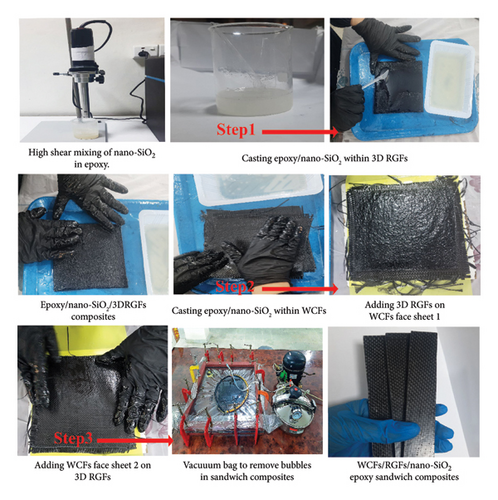
As the first stage in fabricating a sandwich composite, 100 g of EP resin is combined with nano-SiO2 in varying concentrations ranging from 0.01% to 0.8% by weight of resin. Concentrations ranging from 0.01 to 0.8 wt% were used to determine the optimal level for improving the mechanical performance of the sandwich composites. This range was chosen to evaluate both the sandwich mechanical properties and the dispersion quality of nanosilica for achieving the best results [46–48]. The next step is to ensure uniformity by whipping the ingredients together for three minutes at 6000 rpm. 3D RGF foams serve as the core material, and the resulting mixture is poured into them. The 3D RGFs are then covered with face sheets of WCFs in layers of 3, 5, or 7 sheets thick. Once the layering is done, put the assembly in a vacuum bag to ensure a compact and homogeneous structure. This process, which takes 3 h at room temperature, eliminates any air pockets. In addition to eliminating air, the vacuum treatment improves mechanical bonding between the WCFs and the 3D RGF composite. The result is an EP–matrix sandwich composite of WCFs, RGFs, and nano-SiO2. Figure 1 shows the process of cutting the composite before removing it from the vacuum bag in preparation for mechanical performance testing [2, 49].
2.3. Characterization and Testing


3. Result and Discussion
3.1. Mechanical Performance of WCF/EP Composite
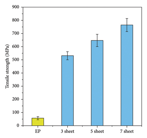
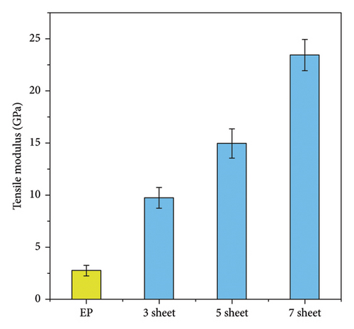
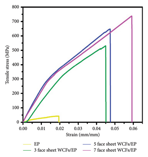
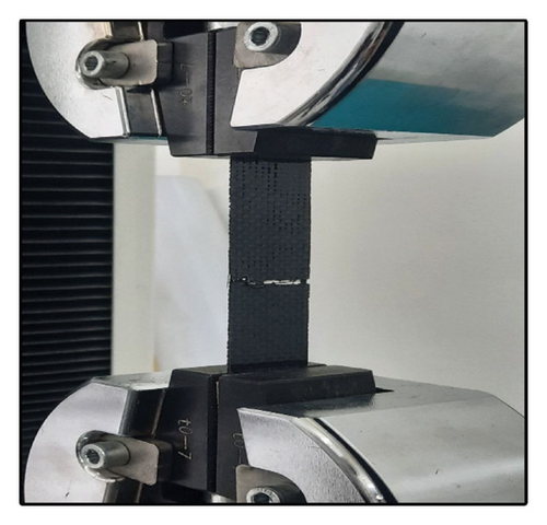
To evaluate the tensile properties of face sheets comprising 3, 5, and 7 layers before incorporating them into sandwich composites, an initial tensile test was conducted. This test focused on the mechanical properties of face sheets made from WCFs and EP (WCFs/EP) composites. Performing these tests beforehand is essential to ensure the sandwich composites achieve optimal mechanical performance. Figure 3 and Table 2 illustrate the tensile performance of the WCFs/EP composites with different face sheet configurations. Figure 3(a) shows a notable increase in tensile strength as more carbon fiber sheets are added, with pure EP having the lowest strength and the 7-layer composite the highest. Specifically, the tensile strength of the EP alone is 57 MPa, which rises to 531.38 MPa with three layers, 647.24 MPa with five layers, and 764.40 MPa with seven layers. Figure 3(b) presents the tensile modulus of WCFs with varying numbers of layers. The tensile modulus for EP is the lowest at 2.75 ± 0.5 GPa. Adding three layers of WCFs significantly increases the tensile modulus to 9.75 GPa. This upward trend continues with five layers, which show a tensile modulus of 14.96 GPa. The highest tensile modulus, 23.44 GPa, is observed with seven layers of WCFs. Figure 3(c) displays the flexural stress–strain curves, indicating enhanced performance with an increasing number of sheets. The 7-layer configuration demonstrates the highest stress and strain at failure. Figure 3(d) shows a sample under flexural load during testing [50–52].
| WCFs layers | Tensile strength (MPa) | Tensile modulus (GPa) | Flexural strength (MPa) | Flexural modulus (GPa) |
|---|---|---|---|---|
| EP | 57 ± 12 | 2.75 ± 0.5 | 80.14 ± 10 | 3.64 ± 0.8 |
| 3 layers | 531.38 ± 31 | 9.75 ± 1 | 600 ± 26 | 48.55 ± 5 |
| 5 layers | 647.24 ± 47 | 14.96 ± 1.4 | 800 ± 28 | 66.81 ± 5 |
| 7 layers | 764.40 ± 50 | 23.44 ± 1.5 | 890 ± 35 | 77.80 ± 6 |
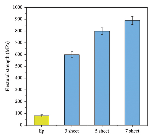
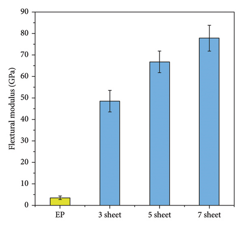
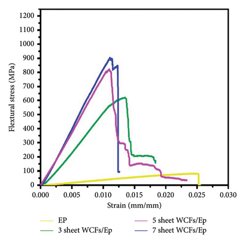
To determine the flexural properties of face sheets with 3, 5, and 7 layers before their use in sandwich composites, an initial flexural test was performed. This test assessed the mechanical characteristics of face sheets composed of WCFs/EP composites. Conducting these tests in advance is critical for ensuring that the sandwich composites achieve the best possible mechanical performance. Figure 4 provides a detailed look at the flexural performance of WCFs/EP composites with various configurations of face sheets. In Figure 4(a), there is a significant increase in flexural strength as the number of carbon fiber layers increases, with the pure EP showing the lowest strength and the 7-layer composite showing the highest. Specifically, the flexural strength for the EP alone is 80.14 MPa, which increases to 600.0 MPa with three layers and 800.0 MPa with five layers and peaks at 890.0 MPa with seven layers. Furthermore, Figure 4(b) depicts the flexural modulus of WCFs with different numbers of layers. The flexural modulus for EP is the lowest at 3.64 GPa. When three layers of WCFs are added, the flexural modulus increases significantly to 48.55 GPa. This trend continues with five layers, which exhibit a flexural modulus of 66.81 GPa. The highest flexural modulus, 77.80 GPa, is achieved with seven layers of WCFs. Additionally, Figure 4(c) illustrates the flexural stress–strain curves, showing improved performance as the number of layers increases. The configuration with 7 layers demonstrates the highest stress and strain at failure. Finally, Figure 4(d) displays a sample undergoing flexural loading during testing.
3.2. Mechanical Performance of WCFs/RGF/EP Sandwich Composites
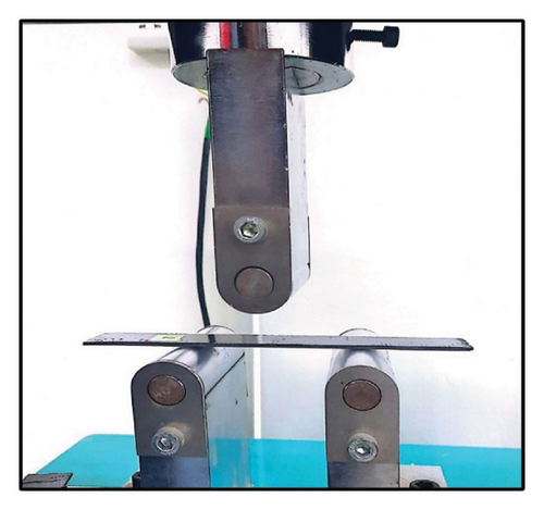
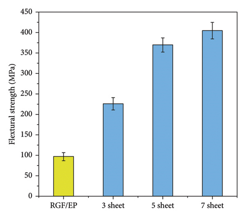
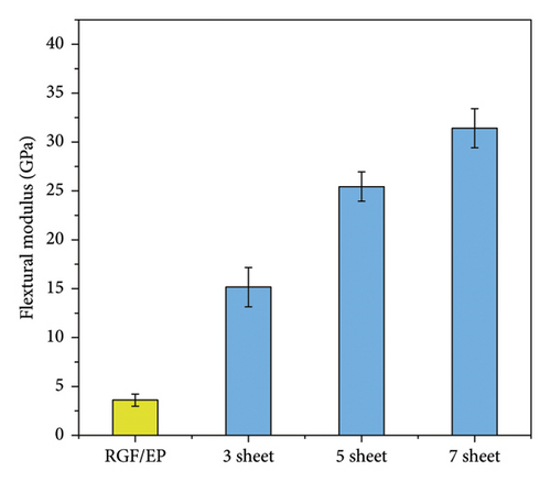
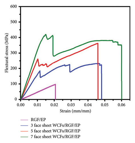
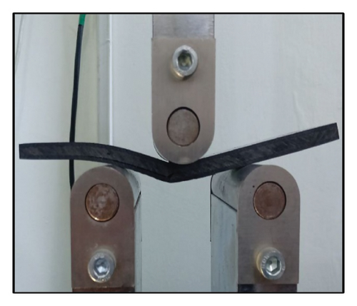
Figure 5 and Table 3 illustrate the impact of adding face sheets of WCFs to the core of 3D randomly oriented carbon felt/RGF/EP) composites on the flexural properties of the sandwich composites. The 3D RGF/EP alone exhibits a flexural strength of 97.14 MPa and a modulus of 3.64 GPa (Figures 5(a) and 5(b)). The data reveal a substantial increase in both flexural strength and modulus with the addition of more CF layers. Adding 3 layers of WCFs significantly enhances these properties, resulting in a flexural strength of 226.92 MPa and a modulus of 15.18 GPa. With 5 layers, the flexural strength increases to 370.21 MPa, and the modulus increases to 25.43 GPa. The highest values are observed with 7 layers, showing a flexural strength of 405.07 MPa and a modulus of 31.38 GPa. The stress–strain curves support these findings, displaying the highest peak stress and strain for the 7-layer composite, indicating superior strength and ductility (Figure 4(c)). Additionally, Figure 4(d) depicts a sample of the sandwich composites under a flexural load.
| No layers of CF | Flexural strength (MPa) | Flexural modulus (GPa) | Facing bending stress (MPa) | Ultimate shear stress of core (MPa) | Fracture energy (MPa) |
|---|---|---|---|---|---|
| RGF/EP | 97.14 ± 10 | 3.64 ± 0.6 | — | — | 1119 ± 150 |
| 3-Layer WCFs/RGF/EP | 226.92 ± 15 | 15.188 ± 2 | 187.40 ± 11 | 11.07 ± 0.5 | 8439.75 ± 400 |
| 5-Layer WCFs/RGF/EP | 370.21 ± 17 | 25.43 ± 1.5 | 246.09 ± 10 | 12.15 ± 0.8 | 11,328 ± 500 |
| 7-Layer WCFs/RGF/EP | 405.07 ± 20 | 31.38 ± 2 | 324.07 ± 15 | 17.80 ± 1 | 19,400 ± 700 |
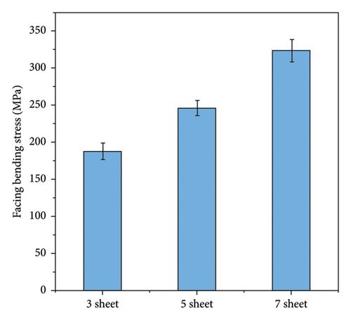
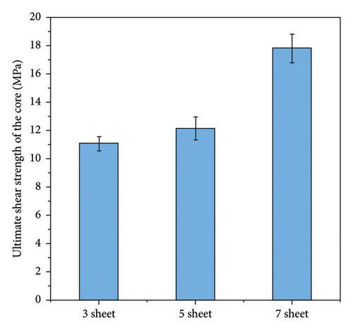
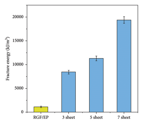
Figure 6(a) illustrates the impact of varying the number of WCF layers (3 to 7 sheets) on the facing bending stress, ultimate shear strength of the core of sandwich composites, and fracture energy. The facing bending stress increases from approximately 187.4 MPa with 3 sheets to about 324 MPa with 7 sheets, indicating enhanced bending resistance (Figure 6(a)). Similarly, the ultimate shear strength of the core rises from roughly 11 MPa for 3 sheets to around 17.8 MPa for 7 sheets, demonstrating improved shear resistance (Figure 6(b)). The fracture energy shows a significant increase from about 1119 kJ/m2 for the RGF/EP baseline to approximately 8439.9 kJ/m2 with 3 sheets, 11,328 kJ/m2 with 5 sheets, and 19,400 kJ/m2 with 7 sheets, reflecting a substantial enhancement in energy absorption before fracturing (Figure 6(c)). Adding more WCF layers significantly improves the composites’ mechanical properties, making them more robust and durable. Carbon fiber EP sandwich composites get better tensile, as well as flexural strength with the addition of more layers due to better load dispersion decreasing localized stress concentration and chances of failure. With each added layer, the cross section is further enlarged making it easier for the composite to resist the application of bending and tensile forces. The other interfaces formed by the fibers and EP also enhance their bond making transference of load better. This likewise facilitated an increase in rigidity, which made it hard to bend the composite structure under a force. Additionally, the existence of several layers exerts another global performance improvement that prevents failure if one layer is compromised, other layers help uphold the structure. Self-strengthening and effects are perfect reasons why stiffness is observed with an increase in layers.
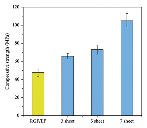
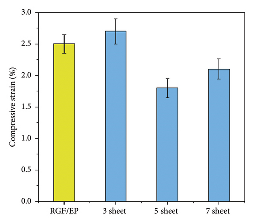
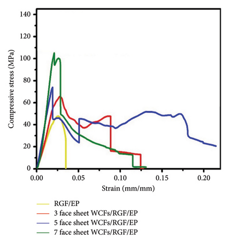
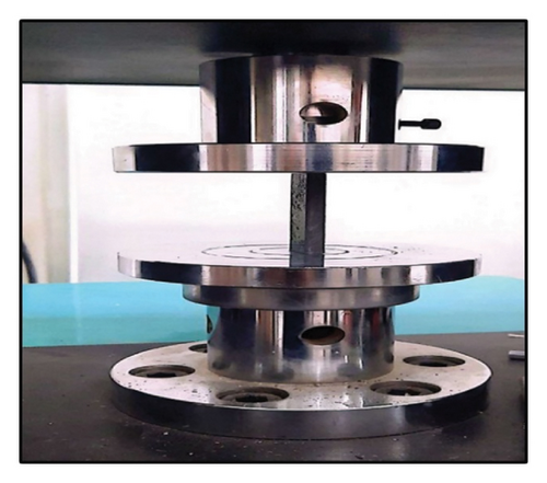
Edgewise compressive tests as shown in Figure 7 and Table 4 were conducted to determine the variation in the strength of the sandwich panel when subjected to compressive stress in the same plane. The objective of the test was to examine the variation in strength based on the thickness of the core and the kind of face used in sandwich panels. Additionally, the test aimed to predict the potential failure mode that a sandwich panel may experience under compressive loading of this nature. The edgewise compressive test involves applying a compressive force to the panel along the facing plane. In this loading scenario, sandwich panels often fail due to wrinkling (dimpling), shear crimping, or total buckling. Obtaining the exact ultimate compressive strength of the face material is uncommon; however, the findings provide a close approximation of its compressive strength [53].
| Samples | Compressive strength (MPa) | Compressive strain (%) |
|---|---|---|
| RGF/EP | 47.6 ± 4 | 2.49 ± 0.15 |
| 3 Layers WCFs/RGF/EP | 65.9.5 ± 3 | 2.71 ± 0.2 |
| 5 Layers WCFs/RGF/EP | 73 ± 5 | 1.8 ± 0.15 |
| 7 Layers WCFs/RGF/EP | 105 ± 8 | 2.1 ± 0.16 |
All three sandwiches exhibit identical behavior during the longitudinal compression test, including buckling. This is evident from the same form of the curves for sandwiches made with 3, 5, and 7 sheets, as shown in Figure 7. The maximum stress and compression for each variation of the sandwich are 65.7, 73, and 105 MPa, respectively (Figure 7(a)). These data indicate that an increase in the number of layers of carbon fiber leads to a corresponding rise in maximum compressive stress. Thus, the maximum stress for 7-sheet layers of WCFs is more than 58% higher compared to EP and 40% higher compared to 3-sheet layers of WCFs. Additionally, the stress for 3-sheet layers of WCFs is more than 30% higher compared to 5-sheet layers of WCFs (Figure 7(b)) [54]. The incorporation of fibers in the material enhances its fundamental strength by providing further reinforcement. This reinforcement aids in the effective dispersion of the load and enhances the material’s ability to withstand deformation when subjected to compression. The carbon fibers enhance the interfacial strength between the fibers and the matrix, hence enhancing the total compressive strength [55, 56]. Figure 7(c) shows a sample of sandwich composites under compression load.
3.3. Mechanical Performance of WCFs/RGF/EP + Nano-SiO2 Sandwich Composites
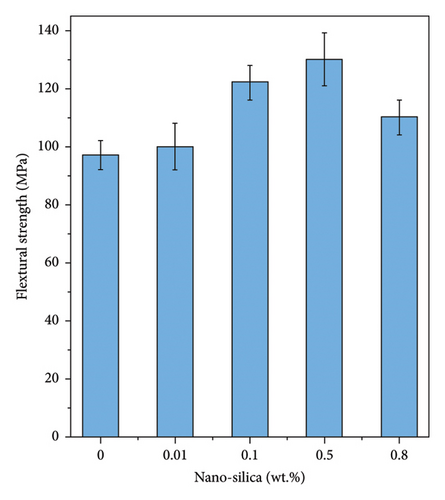
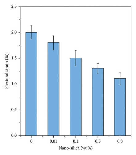
The effect of nano-SiO2 on the flexural properties of 3D graphene-felt-reinforced EP composites (RGF/EP) with different concentrations of nano-SiO2 was studied, as shown in Figure 8 and Table 5. These composites can be used as cores in sandwich structures to increase the mechanical characteristics of the given structures. The data illustrate that increasing the concentration of nanosilica (from 0.01 to 0.8 wt%) in the EP matrix results in an increase in the composites’ flexural strength. With the inclusion of only 3D RGF, the flexural strength and strain were measured at 97.14 MPa and 2% at 0.01 wt% SiO2, respectively. At a concentration of 0.1 wt% SiO2, the flexural strength rose to 122 MPa (an improvement of approximately 25.6%), and the strain decreased to 1.5%. The peak flexural strength, approximately 130 MPa, was observed at 0.5 wt% SiO2, representing an improvement of about 39% compared to the baseline with only 3D RGF. However, at 0.8 wt% SiO2, the flexural strength slightly declined to around 110 MPa (a 33.8% increase compared to the baseline), with a further reduction in strain to 1.1%. These findings suggest that while the addition of nanosilica enhances the composite’s strength, it concurrently diminishes its ductility, with the optimal concentration for maximum strength identified as 0.5 wt%. The increase in flexural strength with the addition of nano-SiO2 is due to the fact that nano-SiO2 also increases the cross-link density within the EP, making the material more rigid and less deformable, which contributes to higher stiffness and strength. However, this increased stiffness reduces the composite’s ductility, resulting in a decrease in flexural strain as the material becomes less capable of plastic deformation. The enhancement in flexural strength with the addition of nano-SiO2 is attributed to the increased cross-link density within the EP matrix, making the material more rigid and less prone to deformation. This rigidity leads to higher stiffness and strength. However, this increased stiffness also reduces the ductility of the composite, causing a decrease in flexural strain as the material becomes less able to undergo plastic deformation.
| Samples | Flexural strength (MPa) | Flexural strain (%) |
|---|---|---|
| RGF/EP | 97.14 ± 5 | 2 ± 0.13 |
| 0.01 wt.%/RGF/EP | 100 ± 8 | 1.8 ± 0.14 |
| 0.1 wt.%/RGF/EP | 122 ± 6 | 1.5 ± 0.15 |
| 0.5 wt.%/RGF/EP | 130 ± 9 | 1.3 ± 0.1 |
| 0.8 wt.%/RGF/EP | 110 ± 6 | 1.1 ± 0.12 |
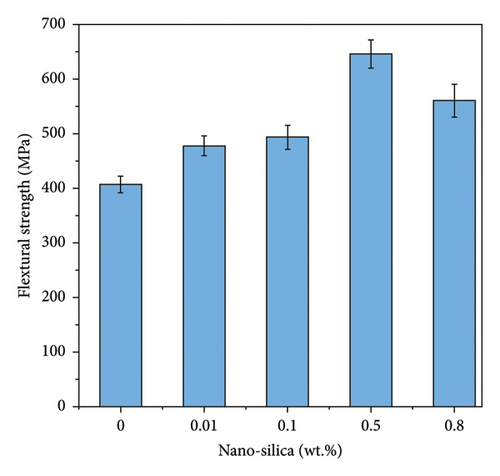
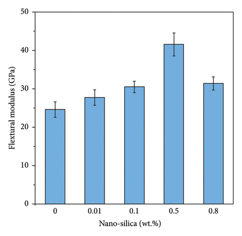
Figure 9 and Table 6 illustrate the effect of nanosilica oxide concentration on the flexural properties of sandwich composites of WCFs/3D RGFs/EP. These composites, composed of WCFs, 3D RGFs, and an EP matrix embedded with nano silica oxides, exhibit varying mechanical properties depending on the concentration of nano-SiO2. As illustrated in Figures 9(a) and 9(b), the flexural strength and modulus of the sandwich composite without nano-SiO2 are approximately 400 MPa and 24.5 GPa, respectively. When 0.01 wt% of nano-SiO2 is added, these values increase to 477.5 MPa and 27.6 GPa, reflecting improvements of 19.4% and 12.7%, respectively. At 0.1 wt% nano-SiO2, the flexural strength and modulus further rise to 493.5 MPa and 30.5 GPa, representing increases of 23.4% and 24.5%, respectively. The most significant enhancement is observed at 0.5 wt% nano-SiO2, with flexural strength reaching 645.7 MPa and modulus at 41.5 GPa, corresponding to improvements of 61.4% and 69.4%, respectively. However, increasing the nano-SiO2 content to 0.8 wt% results in a reduction of flexural strength to 560.1 MPa and modulus to 30.4 GPa though these still represent increases of 40.0% and 24.1%, respectively, compared to the initial values. Figure 9(c) shows typical flexural stress–strain curves of the WCFs/RGF/EP–nanosilica composite.
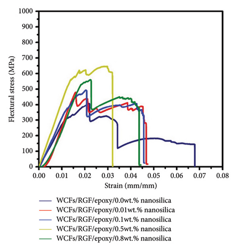
| Samples | Flexural strength (MPa) | Flexural modulus (GPa) |
|---|---|---|
|
400 ± 20 | 24.5870 ± 2 |
|
477.5 ± 18 | 27.7296 ± 1.5 |
|
493.5 ± 22 | 30.022 ± 1.7 |
|
645.7 ± 26 | 41.55728 ± 3 |
|
560.1 ± 30 | 30.48767 ± 1.7 |
3.4. Mechanism Fracture of WCFs/RGF/EP/Nano-SiO2 Composites
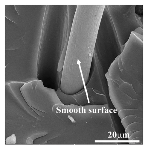
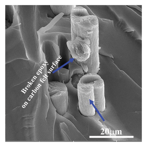
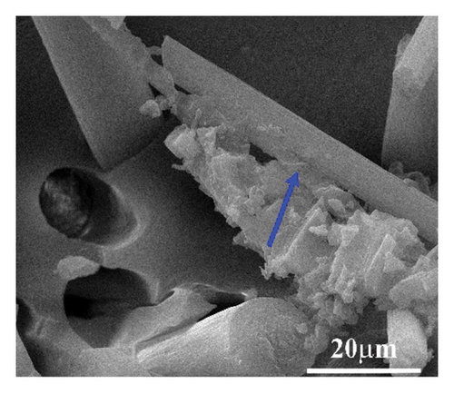
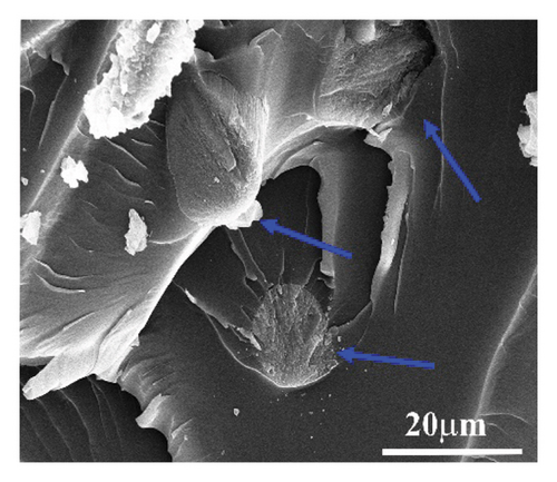
The provided FESEM figures (Figures 10 and 11) illustrate the fracture surfaces of sandwich composite cores made from 3D RGF/EP, modified with varying concentrations of nano-SiO₂ (0–0.8 wt%) at low and high magnifications. Starting with Figures 10(a) and 11(a), which show the composite with 0 wt% SiO₂, there is a visibly rough fracture surface characterized by significant fiber pullouts and smooth fiber surface, indicating poor bonding and interaction between the felt and the EP matrix. In Figures 10(b) and 11(b), with 0.01 wt% SiO₂, there is a slight improvement in structural cohesion, with EP broken and attached on the surface of the fibers (a rough fiber texture), suggesting that even a minimal addition of SiO₂ begins to enhance the matrix–fiber bonding. Moving to Figures 10(c) and 11(c) with 0.1 wt% SiO₂, the fracture surface becomes rougher, and the nano-SiO2 and fibers appear better embedded within the matrix. Figures 10(d) and 11(d), containing 0.5 wt% SiO₂, display a more uniform and denser matrix with consistent fiber distribution, indicating a strong interaction between the matrix, fibers, and nano-SiO2, which leads to higher energy absorption before fracturing. Finally, Figures 10(e) and 11(e), with 0.8 wt% SiO₂, exhibit a lower matrix interface with fiber, suggesting lower enhancements in toughness and durability due to lower dispersion and interaction of SiO₂ particles within the matrix compared to 0.5 wt%. These observations demonstrate that increasing the concentration of nano-SiO₂ to 0.5 wt% in the EP matrix progressively improves the mechanical properties of the composites, enhancing their structural integrity.
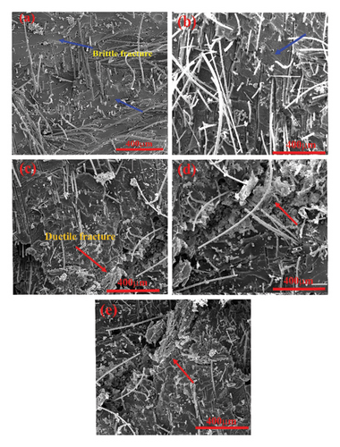
The fracture surface of the sandwich composites with seven face sheets constructed from WCFs/EP, modified with nano-SiO₂ (0-0.8 wt%), was studied using FESEM. Figure 12(a) shows the composite with 0.01 wt% nano-SiO₂, displaying fractured EP on the fiber surface (blue arrows). In addition, Figure 12(b) shows fractured EP on the fiber surface with 0.1 wt% nano-SiO₂, indicated by blue arrows. In Figure 12(c), the composite with 0.5 wt% nano-SiO₂ shows a strong fiber–EP matrix contact, shown by a red arrow. Finally, Figure 12(d) displays the composite with 0.8 wt% nano-SiO₂, displaying a strong contact via a red arrow. These figures show how nano-SiO₂ concentration affects sandwich composite fracture behavior and interfacial bonding. Nanosilica increases interface strength owing to carbon fibers because nanoparticles provide a greater bonding surface area, which improves mechanical interlocking. Nanosilica also refines the composite material’s microstructure, decreasing microvoids and flaws at the interface and making it more cohesive and robust.
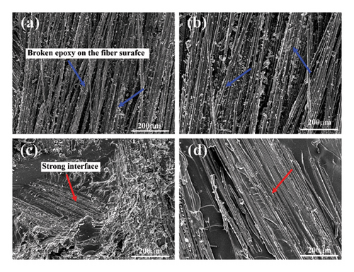
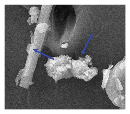
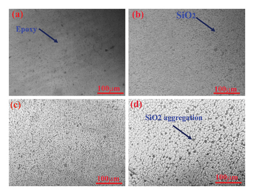
Figure 13 illustrates the dispersion of nanosilica (SiO2) in an EP matrix at different weight percentages. Figure 13(a) shows the EP matrix containing 0.01 wt% SiO2, where the nanosilica particles are sparsely dispersed and appear as black dots, indicating limited particle distribution. In Figure 13(b), with an increase to 0.1 wt% SiO2, a higher dispersion of particles is observed, showing a more uniform distribution across the matrix. Figure 13(c), representing 0.5 wt% SiO2, reveals a significant improvement in the dispersion of SiO2 nanoparticles, covering a larger area of the matrix. This concentration provides optimal distribution, suggesting better interaction between the nanoparticles and the EP matrix. However, as seen in Figure 13(d), further increasing the concentration to 0.8 wt% results in nanoparticle aggregation. This aggregation is evident by the clustering of particles, which could negatively affect the overall performance of the composite by reducing the homogeneity and potentially leading to stress concentrations within the matrix.
4. Conclusion
- 1.
When composite material is made using a pure EP matrix and then reinforced using seven layers of WCFs, the tensile strength of the composite changes minimally from the pure EP value of 57 MPa to a much higher value of 764.40 MPa. There was also a tremendous increase in the tensile modulus from 2.75 to 23.44 GPa indicating a great deal of structural stiffness.
- 2.
The first measurement for the maximum flexural strength was at 80.14 MPa with pure EP and elevated to 890.0 MPa using seven layers of WCFs. On the other hand, the flexural modulus of WCF/RGF/EP composites went much higher than what was achieved with increased bending and deformation resistance of almost 31.38 GPa.
- 3.
A noticeable increase in shear strength and fracture toughness for the core sandwich composites was also made, the ultimate shear strength increasing substantially with the addition of WCF layers while the fracture energy increased from 1119 kJ/m2 (RGF/EP) to around 19,400 kJ/m2 (7-layer WCFs/RGF/EP).
- 4.
The composites displayed a remarkable compression strength of up to 105 MPa with seven layers (7-layer WCFs/RGF/EP), indicative of their capacity to withstand substantial load without failure.
- 5.
The introduction of 0.5 wt% nanosilica to 7-layers WCFs/RGF/EP dramatically improved the flexural strength to 645.7 MPa and the modulus to 41.5 GPa, showcasing the critical role of nano additives in enhancing composite material properties.
Conflicts of Interest
The authors declare no conflicts of interest.
Funding
No funding was received for this research.
Acknowledgments
The authors are grateful to the Technical College Baghdad/School of Materials Engineering laboratories for their valuable help.
Open Research
Data Availability Statement
The data that support the findings of this study are available from the corresponding author upon reasonable request.


