Structural Behavior of Voided Fibrous Sustainable Ferrocement Slabs
Abstract
The global trend at the present time focuses on reducing waste resulting from daily uses and those resulting from manufacturing processes and others, and one of the effective means of reducing waste is to reuse it in concrete in various forms such as powder, fibers, or aggregate. By reviewing previous studies, we cannot find a study on ferrocement voided slabs using plastic bottles. Therefore, this work discusses the fabrication of one-way ferrocement voided slabs using steel meshes and plastic bottles. That is highly helpful in lowering the slab’s weight and reducing waste at the same time. Eight slabs have been tested considering four parameters: type of slab (solid, voided), effect of polypropylene fiber, method for generating voids (using plastic waste bottles, PVC pipe), and number of voided line (one layer, two layers). Besides properties of ferrocements including flowability, compressive and flexural strength has been tested. For all groups, the fibers increased load at first crack, while the presence of hollow did not affect the first crack loading. This because the first crack began for all slabs at the bottom in the tension zone, while the hollow is at the center of the slab where the stress approaches zero near and at the neutral axis. The voids affected the ultimate strength slightly by 2 MPa, but when adding fibers, this loss in strength was restored and the strength of the voided slab increased by 10.7%. But the rate of decrease in strength capacity is unsignificant compared to the benefits obtained from creating a gap, which contributes to reducing dead weight and also creating a sound and heat-insulating surface. This is not the benefit of exploiting waste for this purpose, and all of this has economic and environmental benefits. There is a slight difference (decrease) between the strength capacity of voided slabs including bottles compared to that of PVC pipes about 5.8%. The reason behind this difference is that the tube is a single, integrated piece, while the bottles are in the form of intermittent voids but warped with a fine steel wire mesh in order to form a long, integrated, and continuous voided section. But the failure pattern of slabs containing bottles is more uniform.
1. Introduction
The term “ferrocement” refers to a type of thin-grade RC (reinforced concrete), which is often made of cement mortar reinforced by consistently spaced, generally small, and continuous layers of wire mesh throughout the thickness. Ferrocement reinforcing meshes have high specific surfaces, which causes more bond forces to form with the mortar matrix [1].
Plain concrete and fiber RC have differing tension stiffening capabilities because fiber RC can withstand tension at fractures in addition to strain between them. Depending on the dosage and kind of fibers used, this is leading to a reduction in crack spacing and a considerable amount of postcrack tensile resistance at a crack [2].
There are several uses for ferrocement, such as in building, transportation, agriculture, sanitation, water supply, concrete repair, and structural reinforcement. This is because of several advantages, such as the ease of access to raw materials, the ability to create parts of any design, and the low degree of skill needed for ferrocement assembly. In ferrocement composites with high reinforcement ratios or high-strength meshes, flexural failure results from delamination of the extreme tensile layer of the reinforcement or spalling mortar cover.
These problems can be resolved with the use of discontinuous short fibers in the matrix [3].
Shaheen et al. [4] looked into how ferrocement beams reinforced with fiberglass and polypropylene wire meshes behaved under a three-point load arrangement.
The optimum structural behavior was obtained when four-layer welded wire meshes were used to reinforce the beam instead of fiberglass or polypropylene. It was demonstrated by Shaheen et al. [5] that expanded metal mesh and woven steel mesh work well as reinforcing materials for ribbed ferrocement plates.
In recent years, various fiber types have become more widespread. Waste plastic fibers were used by certain researchers [6]. Additionally, gassy drink cans and the subsequent assessment of studies on the use of aluminum fibers in concrete are the sources of additional used aluminum fibers [7].
Throughout the world, residential and commercial structures frequently use RC hollow core one-way slabs to capitalize on their advantages, economical and thermal insulation in addition to lowering the building’s self-weight. An essential structural component of a building is the slab. A significant amount of materials is consumed by it.
The thickness of the slab grows as the load demand rises, resulting in higher construction costs. Hollow core RC slabs were developed to create affordable slabs with broad spans and modest depths without the need for intermediate support in both single-story and multistory buildings [8]. Slabs with a large span and lower slab self-weight were achieved by using waffle, bubbled, and hollow core slabs (HCSs) [9]. Concrete slabs with continuous voids spanning the length of the slab are known as HCSs. These gaps are used to run mechanical or electrical systems and to lessen the slabs’ weight and cost. Low material usage and good structural efficiency are provided by the HCS [10].
Cuenca and Serna [11] investigated how steel fiber affected HCS behavior. Their findings indicated that adding steel fiber to HCS boosted its ductile behavior and gave it a larger shear capacity than slabs without steel fibers.
The potential use of plastic bottles as cavities inside RC elements in a specific zone where the stresses are very low or equal to zero (the center of voided areas locate or nearby at the neutral axis) has recently been the subject of some research. Installing used plastic bottles inside structural components has several benefits. Reducing the weight of structural components comes first, followed by the provision of concrete [12].
Using discarded plastic bottles placed at the midheight of the concrete beam, Rahadyanto [13] examined the flexural behavior of RC voided beams. About 98% of the moment capacity of the solid beam with the same concrete strength is present in the voided beam with 33.2 MPa concrete strength, according to the data.
The impacts of utilizing waste plastic bottles as voids to create a hollow core one-way slab on the flexural behavior were examined by Orientilize et al. [14]. Three parametric experiments were carried out: the steel fiber content, chopped PET, and void content. In comparison to zero content (solid slab), the PET-studied void content was 19% and 24%. All voided slabs had ultimate moment capacity values that were 12%–16% less than those of the solid slab.
A set of RC beams was put to the test by Mathew and Varghese [15]. Sariman [16] recently investigated three RC beams. The height of the hollow (the number of layers for the waste plastic bottles) was the parametric analysis of the tested specimens, with the first specimen serving as the control.
The second specimen was 60 mm in height, while the third specimen, which consisted of two layers of plastic bottles, measured 180 mm in height. The findings showed that the tested beams’ flexural ultimate capacity was not significantly impacted. The flexural stiffness of 180-mm hollow height is lower than that of 60-mm hollow height in terms of hollow height. It is evident from earlier research that there is no practical method for installing used plastic bottles inside the beam to facilitate work. As a result, a novel technical approach utilizing steel wire mesh is suggested for the placement of used plastic bottles in a bundle at any height of the beam.
The hollow tube used to make the steel wire mesh was once filled with used plastic bottles. This fabrication offers two benefits. First, to swiftly and simply install plastic bottle tubes in a bundle. Furthermore, because of its tensile strength, the steel wire mesh might help raise the ultimate load capacity. This kind of hollow used for one-way slabs has only been studied twice before [12, 17].
The current global tendency is to reduce waste from daily utilization production processes and other sources.
Reusing waste in concrete in different forms is one efficient way to reduce waste. It is hard to find a study on ferrocement voided slabs using plastic bottles by looking through previous studies. Thus, the fabrication of one-way ferrocement voided slabs with steel meshes and plastic bottles is covered in the study. Four factors have been taken into consideration when testing eight slabs: the kind of slab (solid or voided), the impact of polypropylene fiber, the method for generating voids (using PVC pipe or plastic waste bottles), and the number of voided lines (one or two). In addition to the flowability of ferrocements, tests have been conducted on their compressive and flexural strengths.
2. Experimental Work
The cement utilized was Type I, which met Iraqi specification (IS) No. 5 [18]. Table 1 illustrates the usage of sand (fine aggregate) whose size distribution and properties complied with IS No. 45 [19]. Types G and F of Sika ViscoCrete-5930 were utilized as high-range water-reducing and superplasticizing admixtures, and they meet ASTM C 494 standards [20]. Polypropylene fibers were utilized as discontinuous discrete fibers in order to improve the tensile strength of slabs and control the crack propagation. The properties of these fibers are listed in Table 2.
| Sieve size | Passing% | IQ No. 45/1984/Zone 2 |
|---|---|---|
| 4.75 | 100 | 89–100 |
| 2.36 | 94 | 60–100 |
| 1.18 | 75 | 30–100 |
| 0.6 | 45 | 15–100 |
| 0.3 | 15 | 5–70 |
| 0.15 | 2.5 | 0–15 |
| Physical properties | ||
| SG (specific gravity) | 2.72 | — |
| SO3% (sulfate%) | 0.12% | 0.5% max |
| Water absorption% | 0.78% | — |
| FM (fineness modulus) | 2.5 | — |
| Composition | Polypropylene |
| Packaging | 0.6-kg water-soluble bags in boxes containing 30 × 0.6 kg (other size packaging is available on request) |
| Appearance | Color white fiber |
| Density | ~0.91 kg/L (+25°C) |
| Dimensions | |
| Fiber length | ~12 mm |
| Fiber diameter | ~18 μm |
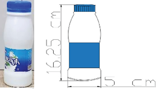
In Iraq, the breakfast table is never devoid of yoghurt, so large numbers of yoghurt bottles are thrown away as waste. Therefore, it was benefited by using it to form voids in ferrocement slabs; Figure 1 shows the details of using plastic bottles. Also, plastic tubes of diameter 5 cm have been used to generate voids. The reason for choosing yoghurt bottles is that their diameter is 5 cm, which is the same diameter as the plastic tubes used, so the diameter is compatible and thus the discussion and comparison are logical. The ferrocement slabs have been reinforced with two layers of rectangular opening welded steel mesh (RWSM) with an opening size of 40 × 80 mm used to support the slabs. According to ACI Committee 549 [21], the laboratory measurements of RWSM’s characteristics showed that its ultimate strength was 350 MPa and its yield strength was 240 MPa. A 1:2 cement:sand mix ratio, 1% SP from cement weight, and a 0.35 w/c (water to cement ratio) have been utilized. As a proportion of mix volume, 0.50% fiber was used.
3. Ferrocement Slab Reinforcing Details
Eight slabs, which have been distributed in four groups, have been tested considering four parameters: type of slab (solid, voided), effect of polypropylene fiber, method for generating voids (using PET waste bottles, plastic tube), and number of voided layers (one layer, two layers), as illustrated in Table 3.
| Group | No. | Slab symbol | Description |
|---|---|---|---|
| 1 | 1 | S-F0 | Solid slab—no fiber added |
| 2 | S-F0.5% | Solid slab—0.5% fiber | |
| 2 | 3 | VB1-F0 | Voided slab with one line of bottle tubes—no fiber added |
| 4 | VB1-F0.5 | Voided slab with one line of bottle tubes—0.5% fiber | |
| 3 | 5 | VB2-F0 | Voided slab with two lines of bottle tubes—no fiber added |
| 6 | VB2-F0.5 | Voided slab with two lines of bottle tubes—0.5% fiber | |
| 4 | 7 | VP2-F0 | Voided slab with two lines of PVC pipe—no fiber added |
| 8 | VP2-F0.5 | Voided slab with two lines of PVC pipe tubes—0.5% fiber |
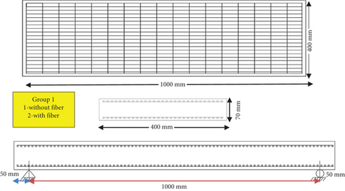
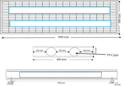
The first group consists of solid slabs without voids and all tested slabs have the same dimensions, which are as follows: 400 mm is the slab’s width, slab thickness is 70 mm, and its total length is 1000 mm (900 mm between the centers of two basic slab supports). All slabs were reinforced with two layers of RWSM with an opening size of 20 × 65 mm, Figure 2 illustrates the details of reinforcing and dimension of slabs in Group 1.
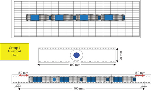
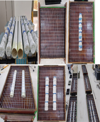
The second group includes the hollow slabs that plastic bottles were used to form the voids. To enclose the plastic bottle as a longitudinal tube, an inventive technique utilizing steel wire mesh constructed in the shape of a tube was used to void out; see Figure 3.
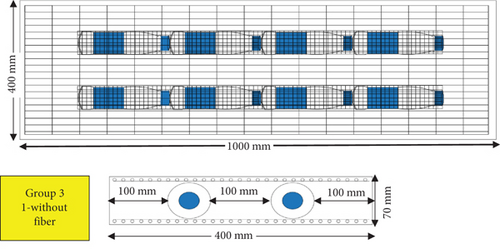
Group 3 differs from Group 2 by having two bundles of hollow-forming bottles; see Figure 4. While in the fourth group, a PVC pipe, with the same diameter and length as the bundle made up of plastic bottles, was used to form the two-line hollow; see Figure 5.
Slab casting was done using wood molds with smooth surfaces that were 1000 × 400 × 70 mm. RWSMs were placed with covers on all sides, about 10 mm. RWSM was evenly dispersed with a slab thickness and identical spacing, with 10 mm separating the two RWSM layers. The molds were taken out after the slabs were cast, and they were left in the treatment basin for 28 h to cure in water. The procedure of preparing the solid and voided ferrocement slabs is shown in Figure 6.
4. Test Setups
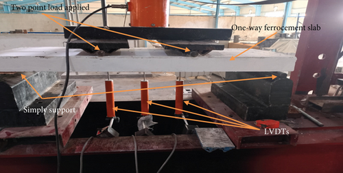
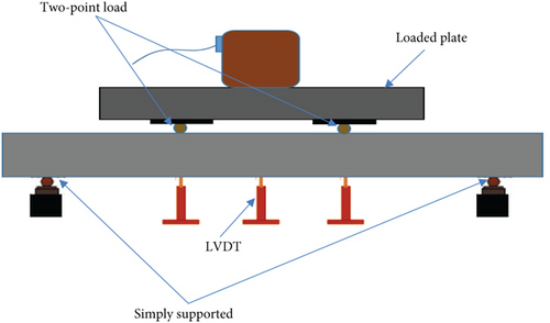
A hydraulic jack machine with a 500-kN capacity was utilized to test eight one-way solid and voided slabs, as illustrated in Figure 7. The load observations were recorded for each 5-kN step and from zero until failure loading along the slab’s length. To quantify the deflection with corresponding load at midspan along the slab, LVDT device was used. Using a two-point loading technique, bending tests were performed to evaluate the one-way simply supported ferrocement slab. A hydraulic jack applied the load, while a computer-based data gathering system collected the load signal. Flow table test was also made based on ASTM C1437 [22] to insure a good workability of mortar before and after adding the fibers. Also, compressive and flexural strength was measured according to ASTM C109 [23] and ASTM C348 [24], respectively.
5. Results of Fresh and Strength Properties
Fibers are usually added to different types of concrete, and the common purpose is to improve the weak tensile strength of concrete and reduce the width of cracks.
The result of flowability, compressive strength, and flexural strength for mixes with and without fibers is listed in Table 4.
| Properties | Mixes | Values | Change% |
|---|---|---|---|
| Flow diameter | Reference | 20 (mm) | — |
| Fibrous mix | 16.5 (mm) | −17.5 | |
| Compressive strength | Reference | 49.00 (MPa) | — |
| Fibrous mix | 50.87 (MPa) | +3.6% | |
| Flexural strength | Reference | 3.80 | — |
| Fibrous mix | 6.250 | +63% |
Workability is the quantity of productive internally generated work required to achieve complete compaction. Water content, mix proportions, admixtures, and the properties of the materials utilized are the main elements that impact workability. For concrete to be placed and compacted successfully during construction activities, optimal workability must be achieved. Adding fibers, and as one can notice from the results shown in Table 4, the workability decreased, and this was inferred by measuring the flow diameter of the mixture, which decreased from 20 to 16.5 mm. The overall surface area of the paste-coated components in the mixture is increased by fibers. Consequently, the obvious effect of more fibers on fresh concrete is typically seen as a decrease in workability or flowability. Since the mixture’s flowability is important to achieve a homogeneous mixture and to avoid the adverse effect of fibers on the flowability, 1% SP was added to keep the flowability within acceptable limits. This result is similar to what other researchers reached who used waste fibers with ferrocement and other types of concrete [7, 25]. But on the other hand, the fibers improved the rest of the properties such as compressive strength, and the most noticeable improvement was in the flexural modulus. The compressive strength only increased slightly, with an increase of 3.6%. It is known that fibers do not have much effect on compressive strength [26].
As for the flexural strength, it increased significantly and by a percentage 63%when fibers were added. This behavior can be attributed to polypropylene fibers’ capacity to reduce the cracks in the concrete matrix. The fiber bridge over the matrix’s crack sections acted by transferring stress from the matrix to the fibers as soon as the crack started and continued, progressively supporting the full load. The fiber RC’s flexural tensile strength was higher than that of the control equivalent due to the stress transfer’s better tensile strain capacity [27].
6. Results of Load–Deflection Relations of Tested Slabs
Within the parameters of the experimental investigation, load–deflection curves for the tested slabs were acquired. The midspan deflection responses and total applied load responses of the plain slabs for polyproline fibers are shown in Figure 8.
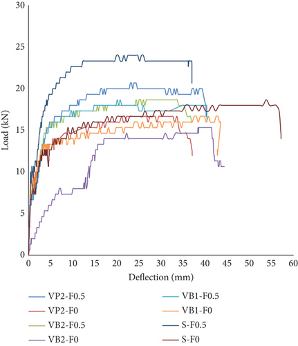
As mentioned before, four parameters have been considered: effect of polypropylene fiber, type of slab (solid, voided), method for generating voids (using plastic waste bottles, plastic tube), and number of voided layers (one layer, two layers). Next, the effect of each factor on the behavior of ferrocement slabs will be presented in detail.
6.1. Influence of Fiber on Solid and Voided Slab Behavior
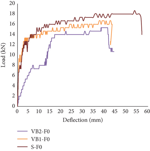
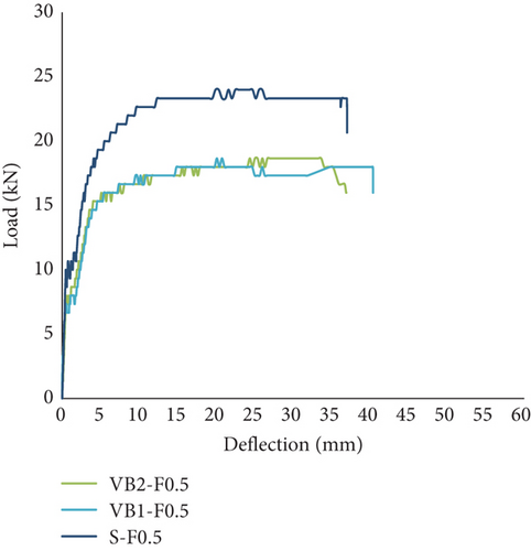
Figures 9a, 9b, 9c, and 9d illustrate the effect of PP fibers on slab behavior. For all groups, the ultimate load strength with corresponding deflection was raised by polypropylene fibers, which also offered significantly more ductile behavior. PP fibers can contribute to the load transfer to the fiber in the matrix when the matrix fails, increasing the material’s tensile flexural strength and enabling the matrix to sustain a higher load. The bearing capacity of the ferrocement slabs is steadily increased till it reached ultimate strength and then decreased rapidly until fracture as the PP fiber on the cracking surface gradually breaks [27]. Besides, the fibers cause increase in ultimate load and improve the ductility of members [28, 29].
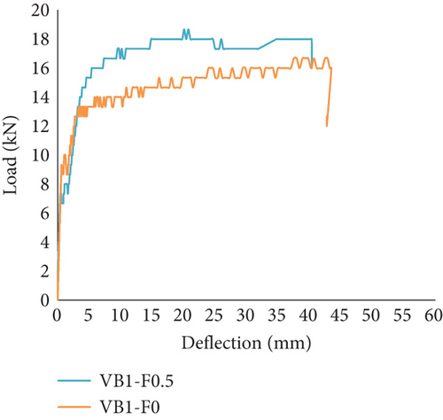

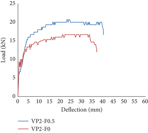
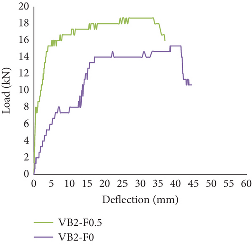
The fiber–matrix bond may have been strengthened as a result. The ideal amount of PP fiber varies depending on the matrix. As a result, increasing the amount of PP fiber in the matrix can increase its bending strength. According to Mohamed [25] and Hakeem [30] the optimal content of PP fibers is 0.5%.
- 1.
Elastic stage: Despite the presence of microcracks inside slabs, the specimen is subjected to a minimal external force, preventing the fractures from spreading. The development of microcracks can be stopped by adding fibers.
- 2.
Elastic–plastic stage: Even though the fibers just stop the fractures from widening, they do so nonetheless as the external load increases [31].
- 3.
Yield stage: Critical stress propagation is occurring, and the cracks are still growing.
- 4.
Fracture stage: The cracks reach the crucial length and expand steadily. Cracks propagate through the cement paste throughout the load deflection process of the slab, although the slab’s strength and stiffness remain minimal.
6.2. Influence of Voids on Slab Behavior
Now to discuss the effect of incorporating hollow in slabs, Table 5 illustrates the summary of the results.
| No. | Slab | Pcr | △cr | Pmax | △max |
|---|---|---|---|---|---|
| 1 | S-F0 | 7.5 | 1.28 | 18.65 | 57.17 |
| 2 | S-F0.5 | 8.66 | 0.62 | 23.98 | 36.99 |
| 3 | VB1-F0 | 7 | 0.53 | 16.65 | 42.75 |
| 4 | VB1-F0.5 | 8 | 0.38 | 18.65 | 40.37 |
| 5 | VB2-F0 | 8 | 1.78 | 15.32 | 41.42 |
| 6 | VB2-F0.5 | 8.7 | 1.11 | 17.5 | 36.91 |
| 7 | VP2-F0 | 6.5 | 0.39 | 16.28 | 37.07 |
| 8 | VP2-F0.5 | 7 | 1.09 | 18.85 | 40.19 |
For all groups, the fibers increased load at first crack, while the presence of hollow did not affect the first crack loading. This because the first crack began for all slabs at the bottom in the tension zone, while the hollow is at the center of the slab where the stress approaches zero near and at the neutral axis. The hollow affected the ultimate strength slightly. The ultimate recorded load decreased from 18.65 kN for slab S-F0 to 16.65 kN for VB1-F0. And the ultimate recorded load decreased from 23.98 kN for slab S-F0.5 to 18.65 kN for VB1-F0.5.
Increasing the hollow from one line to two causes a further decrease in the strength capacity of slabs, which is represented by the maximum recorded load. The ultimate recorded load decreased from 16.65 kN for VB1-F0 to 15.32 kN for VB2-F0. The ultimate recorded load decreased from 18.65 kN for VB1-F0.5 to 17.5 kN for VB2-F0.5; see Figure 10a,b. This is due to a decrease in stiffness, which reflects on the whole behavior of slabs. However, the rate of decrease in strength capacity is insignificant compared to the benefits obtained from creating a gap, which contributes to reducing dead weight and also creating a sound and heat-insulating surface. This is not the only benefit of exploiting waste for this purpose, and all of this has economic and environmental benefits.
The idea behind voided slabs is to use hollow plastic formers in place of the useless concrete in the middle of a flexural slab [32]. The reduction in concrete is the most evident benefit of flat plate voided slabs. When compared to solid slabs with comparable spans and strengths, voided slabs can lower the amount of concrete by up to 35% if they are built effectively [33]. Because less dead load is applied to the remainder of the building due to the less concrete, the columns and foundations will be smaller.
A reduced base shear for the seismic lateral loads will result from a smaller slab self-weight, which will also lower the structure’s effective seismic weight. Additionally, this would result in smaller lateral force-resisting system members, which would save even more money and eventually lower the structure’s cost. It would also benefit the environment if less concrete was required for a project. Portland cement, one of the primary ingredients in concrete, emits a lot of carbon dioxide into the atmosphere during manufacture [34]. However, creating gaps in the slabs to lower the volume of concrete has yet another significant benefit.
Similar findings were made by Kanagaraj et al. [35], who discovered that insulated hollows in wall panels alter the failure type from brittle to ductile and that the EPS (expanded polystyrene), which is used to form the hollow, has an elastic property that keeps the encased concrete in its core after the failure.
6.3. Influence of Method of Forming the Voids on Slab Behavior
Most of the previous studies on voided slabs find the use of PVC pipe to form the voids [36–38]. A limited number of studies were found that used plastic drinking water bottles to form voids in slabs, but they were used in normal concrete and not ferrocement [14, 15, 17, 39]. In addition, we did not find a study comparing the voided formation method using pipes with that using waste bottles. In this section, a comparison is made between two groups of hollow ferrocement slabs; Group 3 includes two hollow lines formed using yogurt plastic bottles and Group 4 includes two hollow lines formed by PVC plastic pipe. The reason behind using yogurt plastic bottles instead of drinking water is because the diameter of these types of bottles is the same as that of the PVC pipe. Figure 11a,b illustrates the method of forming the hollow on load–deflection curves of tested ferrocement slabs.
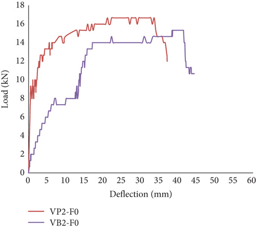
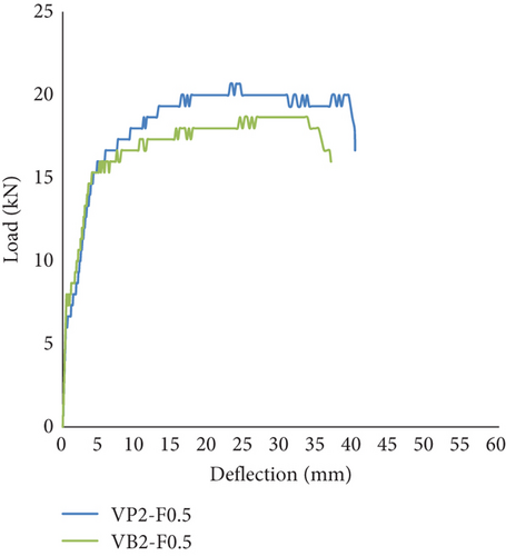
The ultimate recorded load decreased from 15.32 kN for VB2-F0 to 16.28 kN for VP2-F0. And the ultimate recorded load decreased from 17.5 kN for VB2-F0.5 to 18.85 kN for VP2-F0.5.
There is a slight difference (decrease) between the strength capacity of voided slabs including bottles compared to that of PVC pipes. The reason behind this difference is that the tube is a single, integrated piece, while the bottles are in the form of intermittent voids but warped with a fine steel wire mesh in order to form a long, integrated, and continuous voided section. But as one can see in the next section, the failure pattern of slabs containing bottles is more uniform.
Using empty plastic bottles instead of PVC pipes has both environmental and economic benefits. It helps recycle these wastes, keeping them out of the environment and reducing waste accumulation. At the same time, these bottles are inexpensive. Then, this research discusses the use of plastic bottles and steel mesh to fabricate one-way ferrocement slabs. This is very useful in reducing the weight of the slabs while simultaneously reducing waste. This new innovation is the beginning of a proposal to build a modern and sustainable system of voided ferrocement slabs. As previously mentioned, reducing the need for cement in a project would also benefit the environment. Portland cement, a key ingredient in concrete, releases large amounts of carbon dioxide into the atmosphere during manufacturing [34].
7. Mode of Failure, Crack Propagation, and Crack Width
The failure shape of the tested slabs is depicted in Figure 12. The primary conclusions of this study were that, although internal longitudinal voids in the body of the reinforced ferrocement slab affected initial stiffness, the ultimate capacity was little decreased. The first cracking was observed in the midspan of all slabs, where the largest moment formed with loads between 6 and 8 kN. Voided specimens rupture with lower stresses than the reference slab because of the direct decrease in the moment of inertia brought about by the elimination of a sizable volume of concrete by voids. As shown in Table 5, the decrease in cracking load became more noticeable as the number of lines of voided specimens rose.
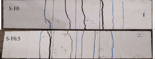
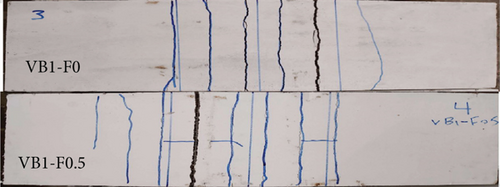
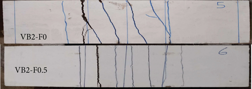
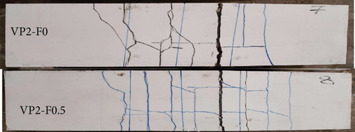
All slabs failed in flexure and vertical splits and cracks formed and spread along the flexural span as the applied weights were increased. Then, as the weight increased, the fractures grew, spread, and multiplied. The presence of flexural cracks near the upper part at the middle third of the slab depth and the crushing of concrete on the top surface of samples at the midspan and along the specimen’s breadth were indicators of flexural failure in these slabs.
The spacing between slabs and the width of slabs have been measured and recorded as in Table 6.
| No. | Slab | Ave. crack width | Ave. spacing between cracks |
|---|---|---|---|
| 1 | S-F0 | 0.48 | 11.58 |
| 2 | S-F0.5 | 0.25 | 9.3 |
| 3 | VB1-F0 | 0.55 | 8 |
| 4 | VB1-F0.5 | 0.45 | 6.64 |
| 5 | VB2-F0 | 0.65 | 9.875 |
| 6 | VB2-F0.5 | 0.46 | 6.75 |
| 7 | VP2-F0 | 0.75 | 10.67 |
| 8 | VP2-F0.5 | 0.58 | 8.64 |
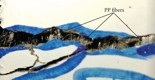
For all slabs, the presence of fibers effectively contributed to reducing the crack width and transforming the failure from a brittle failure with a specific number of widely spaced cracks to a flexible failure, where we find a slightly higher number of cracks but with a lower width and close distribution, and the increase in the number is also due to the increased load at failure, in which the slabs containing fibers need for a longer period of time before they fail. PP fibers can contribute to the load transfer to the fiber in the matrix when the matrix fails, increasing the material’s tensile flexural strength and enabling the matrix to sustain a higher load. The fiber bridge over the matrix’s crack sections acted by transferring stress from the matrix to the fibers as soon as the crack started and continued, progressively supporting the full load; see Figure 13.
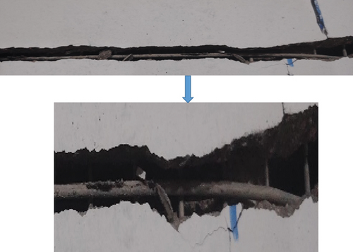
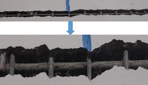
To illustrate the mechanism of the effect of fibers on the width of the crack, Figure 14 represents an image of the crack in a slab free of fibers and another containing fibers. As is clear from the close-up shape of the crack, the crack width is less in the slab containing fibers. It can also be noticed that the reinforcing steel is more deformed in the slab without fibers, because the fibers, in addition to their contribution to reducing the crack width, also contribute to transferring tensile stresses, and thus, the flexural resistance of slabs containing fibers increases.
In general, the presence of voids increases the number and width of the crack and increases with the number of void lines. But the interesting thing is that the number and width of cracks in the voided slab made by plastic bottle are less than those in the voided slab containing a PVC pipe.
The reason behind this behavior may be the smooth surface of the PVC pipe, which reduces the bond strength between it and the surrounding mortar, while in the case of bottles, they are covered with a fine steel wire mesh, which enhances the bond with the surrounding mortar, leading to more uniform failure.
8. Conclusions
- 1.
Adding fibers led to a reduction in the workability of mortar by 17.5%, and this was inferred by measuring the flow diameter of the mixture, which decreased from 20 to 16.5 mm.
- 2.
The compressive strength only increased slightly, with an increase of 3.6%, while the flexural strength increased significantly and by a percentage of 63% when fibers were added.
- 3.
PP fibers contributed to the load transfer to the fiber in the matrix when the matrix fails, increasing the material’s tensile flexural strength and enabling the matrix to sustain a higher load.
- 4.
For all groups of tested slabs, the fibers increased load at first crack, while the presence of hollow did not affect the first crack loading. This is because the first crack began for all slabs at the bottom in the tension zone, while the hollow is at the center of the slab where the stress approaches zero near and at the neutral axis.
- 5.
The voids affected the ultimate strength slightly by 2 MPa, but when adding fibers, this loss in strength was restored and the strength of the voided slab increased by 10.7%.
- 6.
There is a slight difference (decrease) between the strength capacity of voided slabs including bottles compared to that of PVC pipes by about 6% for slabs without fibers and 5.8% for slabs with fibers. The reason behind this difference is that the tube is a single, integrated piece, while the bottles are in the form of intermittent voids but warped with a fine steel wire mesh in order to form a long, integrated, and continuous voided section.
- 7.
All slabs failed in flexure, and the presence of voids increases the number and width of the cracks and increases with the number of void lines. But the interesting thing is that the number and width of cracks in the voided slab made by plastic bottle are less than those in the voided slab containing a PVC pipe.
- 8.
The reason behind this behavior may be the smooth surface of the PVC pipe, which reduces the bond strength between it and the surrounding mortar, while in the case of bottles, they are covered with a fine steel wire mesh, which enhances the bond with the surrounding mortar, leading to more uniform failure.
This study is limited to investigating the behavior of one-way voided ferrocement slabs with and without PP fibers. This study needs to be expanded to include the behavior of two-way voided ferrocement slabs and also to study the effect of other types of fiber, preferably from recycled materials such as plastic, steel, and aluminum fibers.
Conflicts of Interest
The authors declare no conflicts of interest.
Funding
No funding was received for this manuscript.
Open Research
Data Availability Statement
Research data are not shared.


