The Power Grid Inertia With High Renewable Energy Sources Integration: A Comprehensive Review
Abstract
The accelerating integration of renewable energy sources (RESs) into power grids poses a significant challenge to system inertia, primarily due to a reduced dependence on conventional synchronous generators (SGs). This transition profoundly affects frequency stability, rendering grids more susceptible to disturbances. This review offers an in-depth examination of contemporary and emerging strategies to bolster grid inertia, with a focus on virtual synchronous machines (VSMs), advanced energy storage systems, and the transformative potential of artificial intelligence (AI) in optimizing inertia emulation. Unlike prior reviews that primarily catalog existing approaches, this work distinguishes itself by presenting a comparative analysis of various VSM topologies tailored to distinct RES integration contexts, supplemented by real-world case studies and a comprehensive SWOT analysis of AI-driven inertia solutions. The results provide practical insights and guidance for both researchers and industry professionals, underscoring the importance of these adaptive strategies in fostering resilient, sustainable power systems essential for the energy transition.
1. Introduction
Power system stability depends on balancing generation and demand, with grid frequency as an indicator of this balance [1]. The grid frequency is typically maintained at 50 Hz (or 60 Hz in some countries) to ensure stability. A decrease in frequency indicates that demand exceeds generation, and vice versa [2] (see Figure 1). In traditional power grids, frequency stability is maintained by synchronous generators (SGs) and ancillary protection systems [3].

The net-zero carbon politics drives many countries to the utilization of decarbonized and decentralized systems [4]. However, the high injection of renewable energy sources (RESs) causes a major perturbation in grid frequency and increases the rate of change of frequency (RoCoF) and frequency deviation [5]. The speed of frequency changing after an unexpected imbalance between load and generation is called the RoCoF [6]. The RoCoF is measured in Hz/s and its main job is detecting islanding and disconnection of generation units. After the high penetration of RESs, the majority of countries were obliged to change their RoCoF relay standard [7, 8]. For example, Denmark changed the RoCoF relay standard from 0.75 Hz/s to 2.5 Hz/s [8] (see Table 1).
| Country | RoCoF previous standard (Hz/s) | RoCoF updated standard (Hz/s) |
|---|---|---|
| Great Britain | 0.2 | 0.5 |
| Ireland | 0.5 | 1 |
| South Africa | 0.5 | 1.5 |
| Spain | 0.4 | 2 |
| Finland | 0.75 | 2 |
| Denmark | 0.75 | 2.5 |
Some reviews have been made about inertia emulation and enhancement. In [9], the authors discussed some VSM topologies. They also compared two topologies (virtual synchronous machine zero inertia (VSM0H) and universal VSM) and tried to distinguish the performances of each technique. In [10], some inertia emulation techniques were reviewed. The authors in [10] focused more on the methods of enhancement of wind turbine’s (WT’s) inertia. Ratnam, Palanisamy, and Yang [11] have tried to summarize some inertia enhancement techniques and covered some old and new methods for inertia emulation. In [12], the authors examined the integration of renewable energy (RE) in sustainable development, its environmental impact, recent trends, and technical and operational challenges including frequency stability and power quality. Various sources of inertia and their corresponding control strategies have been comprehensively examined in [13]. Additionally, a modified interval-based optimal generation mix formulation has been proposed in [14] to ensure adequate inertial response and power frequency stability while supporting the expansion of RES.
Previous studies have reviewed various inertia emulation techniques and their applications in low-inertia systems. However, while these studies cover essential aspects of grid inertia, they often lack a forward-looking perspective on artificial intelligence (AI) as a potential solution for enhancing inertia emulation. Table 2 presents a comparative overview of similar studies in the field of grid inertia with high-RES integration. It highlights their primary focus, the techniques they emphasize, the specific challenges they address, and the unique contributions of each. This table underscores the unique contributions of our review, particularly its exploration of AI-driven solutions, practical case studies, and a SWOT analysis on AI-based inertia solutions.
| Study | Focus areas | Inertia emulation techniques | Challenges addressed | Unique contributions |
|---|---|---|---|---|
| Ratnam, Palanisamy, and Yang (2020) [11] | Inertia enhancement in low-inertia power systems | VSM topologies, synchronous condensers | Frequency stability with high RES | Comparison of conventional versus advanced VSM topologies |
| Muftau and Fazeli (2022) [9] | VSM implementation in modern grids | Virtual synchronous machines, energy storage | Grid stability and transition to RES | Analysis of VSM effectiveness across different RES integration levels |
| This study | Comprehensive review of inertia with high-RES integration | AI-enhanced VSMs, ESSs, wind turbines, condensers | Frequency stability, cost, operational feasibility | Forward-looking AI role, practical applications, SWOT on AI, unique case studies |
This review not only synthesizes current inertia enhancement methods but also explores the transformative potential of AI in addressing grid stability. By focusing on practical applications and a SWOT analysis, our study provides a holistic perspective that aims to guide future research and industry efforts in achieving resilient and sustainable power grids.
This article thoroughly examines techniques for enhancing inertia, discussing potential challenges associated with each method and highlighting technical issues related to integrating virtual inertia into the power grid. The article also investigates futuristic solutions that incorporate AI to predict and optimize VSM’s inertia emulation. Figure 2 includes a flowchart detailing the process for conducting this study.
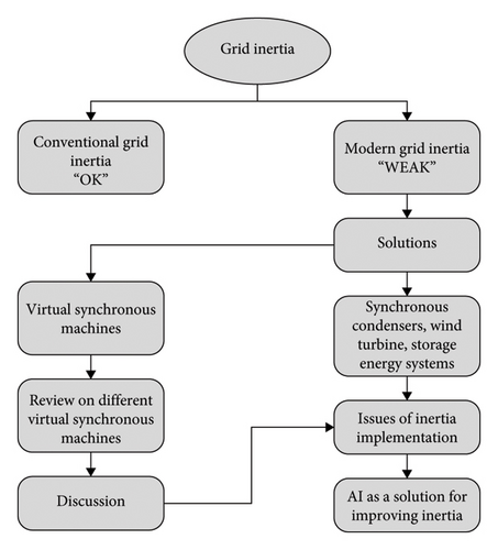
The paper is organized as follows. Section 2 explores inertia in the conventional power grid. Section 3 presents techniques to enhance inertia. Section 4 investigates and discusses various control topologies for VSMs. Section 5 highlights the technical challenges and issues related to enhancing inertia. Section 6 proposes the use of AI as a solution to predict and regulate power system frequency perturbations. In Section 7, a series of case studies are presented, along with their respective applications. Lastly, Section 8 provides a conclusion.
2. Inertia in Conventional Power Grid
SGs are the most utilized in the traditional power system generation for all types of conventional sources such as coal, natural gas, nuclear, and hydroelectric [15, 16]. Frequency stability is achieved through the rotating mass of the SG [17, 18]. In frequency events or power imbalance (load/generation variations), the rotational speed will be adapted by inertia and controller actions [19]. In this way, the synchronism is maintained and the grid is protected from big stability issues and blackouts.
However, the penetration of RESs reduces the inertia in the power grid. SGs could assure inertia and grid stability only if the penetration of RESs is less than its capacity in the power system [20]. So, more the penetration of RESs increases, more the inertia of the system decreases. In future power systems, the integration of RESs is going to be significantly greater, so the RoCoF and frequency deviation will increase too [21]. Figure 3 presents an example of the drop of the equivalent inertia constant Heq in some European countries due to the integration of RESs.
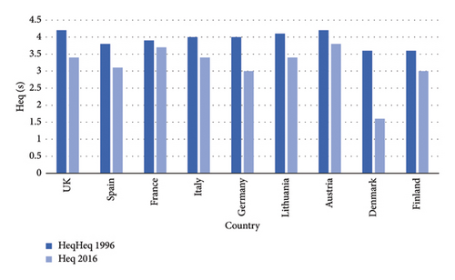
The equivalent inertia constant Heq is the power system’s global inertia. Figure 3 proves that the injection of more RESs in power systems decreases the impact of SGs on maintaining the inertia at its higher levels.
3. Techniques to Enhance the Inertia
To maintain power system stability under high-RES penetration, grid inertia must be increased. In this section, some new and old techniques to enhance and emulate inertia will be presented.
3.1. Synchronous Condensers (SCs)
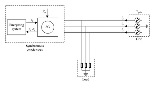
SCs are free-spinning SGs that are connected to the grid [23]. The main goal of these SCs is to regulate the voltage by absorbing or injecting the reactive power [24]. Generally, all SGs without loads are considered as SC [25]. SC can enhance the inertia of the grid power system due to its rotating mass (the rotor) [26] (see Figure 4).
It can be derived from these equations that the system inertia constant can be increased by increasing the individual inertia of each generator composing the system.
- •
High operational cost: Generally, SG uses gas, coal, oil, or even nuclear reactions. So, the cost of these resources is high, and the majority of the time these SGs run without loads, which does not make this method cost-effective [19].
- •
The installation cost: Installing an SG power station only to regulate the inertia is not a powerful solution [19] (economical point of view).
- •
The utilization of fossil fuels: The first objective of using RESs is to reduce CO2 emissions [29]. So, using this technique will not help the case.
SCs contribute to grid stability through natural inertia, making them reliable for sustained support. Yet, their dependence on traditional energy sources and high operational costs poses challenges for high-RES grids aiming for sustainability. Despite these limitations, SCs remain effective in stabilizing grids with high renewable penetration.
3.2. WTs
As a RES, wind is the most promising power. It is available day and night throughout the year. WTs are one of the most powerful RESs. Wind generation systems are spreading rapidly (through the different levels of the power grid), especially double-fed induction generators (DFIGs). For the inertia emulation, WTs make a huge contribution which makes wind energy more attractive [30, 31]. WTs could increase the inertia of power systems with their dominating topologies such as DFIG, fixed speed induction generator (FSIG), and permanent magnetic synchronous generator (PMSG) [32, 33].
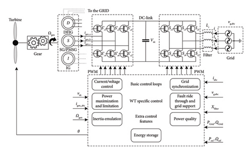
DFIG is connected directly to the grid by the stator which gives it a powerful inertia. The rotor is connected to the power network through a back-to-back converter (grid side and generation side) to regulate the DC-link voltage and the reactive power (grid side) and to control the active power, rotor speed, and also sometimes the reactive power (generation side) [34, 35]. PMSG is connected by its stator through a back-to-back converter. PMSG is characterized by its simplified gearbox, speed, and power controllability [36]. FSIG is directly connected to the grid by its stator which gives it a strong inertia [37]. Different control systems are added to enhance the inertia of WTs, i.e., blade pitch angle control and power electronics control systems [38, 39]. Further details will be discussed in Section 4.1.2. This technique is powerful and green but the high cost of wind energy technology and the irregularity of wind power (the speed of wind and limited windy regions) are the biggest obstacles to the utilization of this technique [40].
Figure 5 shows the WT schema for inertia enhancement.
3.3. Storage Energy Systems
These techniques consist of the use of energy storage systems (ESSs) such as capacitors, ultracapacitors, batteries, and flywheels for the reinforcements of highly penetrated RES grid inertia. This technique is based on charging and discharging the ESS to provide active power to the electrical grid. This means that the ESSs must be 50%–80% charged to make up for the missing power to the power grid or to store the excess energy produced by renewable generators in the moment of power/frequency disturbance [41]. Many techniques and topologies are proposed.
3.3.1. DC-Link Capacitor
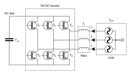
As a result, DC-link is utilized to emulate the inertia (virtual inertia) in the power grid by the use of different control algorithms. A typical scheme of a DC-link capacitor is shown in Figure 6.
3.3.2. Ultracapacitor
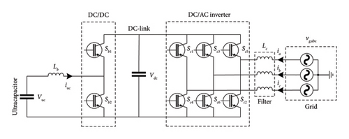
The high performance, the high discharge current, and the charge-discharge cycle life make supercapacitors suitable for providing pulse power for primary frequency response [46]. The supercapacitor is utilized when a DC-link capacitor is insufficient or some frequency support functions are required. Many topologies have been described in [41]. A typical scheme of an ultracapacitor is shown in Figure 7. Its high efficiency, fast load response, modularity, long lifetime, no maintenance requirements, and environmentally friendly characteristics make it a good alternative to batteries in many applications [47]. It delays frequency nadir and RoCoF decreases significantly and gives sufficient time for other sources to respond to the frequency deviation. However, it does not have a long discharge time. In consequence, it has a short operation time.
3.3.3. Batteries
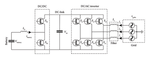
The battery is an electrical storage element. It is characterized by its high density of energy, fast response, moderate cost, and long discharge time which puts it above all ESSs for frequency control and regulation [32]. The battery operates at a direct current. It needs a stable and fixed voltage in normal charging mode. The use of power electronic converters and a proper control algorithm is necessary to regulate the output power and emulate the inertia [48]. Different topologies are represented in [49]. Batteries could be connected to the grid through DC-link as mentioned in Figure 8.
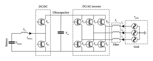
The response time of batteries is longer than supercapacitors. In addition, the discharging time of batteries is much longer than the discharging time of supercapacitors. To benefit from the advantages of both ESSs, a proposed technique is given in [50]. The authors proposed a hybrid system with both batteries and ultracapacitors. The topology scheme is shown in Figure 9. As a result, the system will respond faster and operate longer.
3.3.4. Flywheels
Figure 10 represents the schema of the flywheel for inertia support. Flywheel is considered a powerful ESS due to its fast response and long cycle life [52, 53]. This ESS has an important inertia and good flexibility providing ancillary services in the power grid such as frequency regulation and voltage support [54, 55]. In [56], a frequency control method for a microgrid-connected flywheel ESS has been proposed. This control method has led to a fast power injection and less DC-link voltage variation. A comparison between different control schemes of the flywheel ESS has been made in [57]. A flywheel and lithium battery hybrid energy storage control strategy for smoothing PV systems has been proposed in [58].
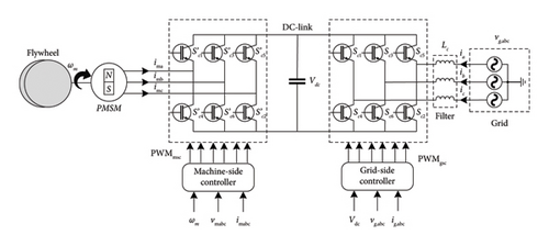
ESSs such as batteries and flywheels provide valuable support for frequency stability, with flywheels excelling in short-term frequency response and batteries offering extended support during prolonged deviations. However, the high initial cost of ESSs and their sensitivity to discharge rates limit their universal application. Hybrid ESS configurations can mitigate some of these challenges by combining rapid response with sustained support.
3.3.5. Hydropower
Hydropower accounts for 99% of global electricity storage, playing a crucial role in ensuring a reliable power supply [59]. Pumped storage micro-hydroelectricity plants (PS-MHPPs) have two modes of operation: generation and pumping. During grid power shortages, water from the reservoir generates electricity in the generation mode, while surplus power in the grid pumps water back to the reservoir in the pumping mode. To ensure consistent power generation, PS-MHPPs require a modern control scheme that can adapt to rapid variations and fluctuations in power production. To address this issue, power electronic converters are utilized to separate the machine from the traditional power grid. Adjustable speed units are used to improve efficiency. The precise control of power production in PS-MHPPs with power converters contributes to the frequency stability of the power grid [60]. However, the introduction of power converters reduces the inertia contribution of PS-MHPPs. Table 3 gives a qualitative comparison between the methods cited above.
| Technology | Inertia compensation | Cost | Functions | Problems | Proven | References |
|---|---|---|---|---|---|---|
| Synchronous condensers | High | High | Reactive power compensation and voltage control | Nonrenewable sources | Yes | [22, 61–63] |
| Wind turbines | High | Medium | Frequency control and renewable source | Nonlinear inertia emulation | Yes | [64–66] |
| DC-link capacitor | Low | Low | DC-link voltage support and harmonic filtering | Sizing of DC-link capacitors | No | [44, 67, 68] |
| Ultracapacitor | High | High | Frequency control | Sizing and placement of ultracapacitors | No | [41, 50] |
| Batteries | High | High | Frequency control | RoCoF measurement, sizing, and placement of batteries | No | [69, 70] |
| Flywheels | High | High | Reactive power compensation and voltage control | — | No | [53, 71] |
| Hydropower | High | High | Frequency control and renewable source | Dependency on water availability and land use | Yes | [59, 60] |
Table 3 presents a summary of the above inertia enhancement techniques, and Table 4 presents a qualitative comparison of the costs associated with various inertia enhancement techniques. As illustrated, SCs and flywheels have high costs due to their reliance on mechanical components and energy sources. On the other hand, battery systems and ultracapacitors are promising but also come with high initial investments. WTs offer a medium-cost solution but are contingent on environmental conditions.
| Technology | Initial investment | Operational costs | Maintenance costs | Comments |
|---|---|---|---|---|
| Synchronous condensers | High | High | High | Effective, but costly due to reliance on conventional energy and complexity |
| Wind turbines (with VSMs) | Medium | Medium | Medium | Renewable source, reliable but subject to wind availability |
| DC-link capacitors | Low | Low | Low | Limited inertia compensation, primarily supports DC voltage regulation |
| Ultracapacitors | High | High | Medium | Quick response, but expensive and short operational times |
| Batteries | High | Medium | Medium | Excellent for long-term support, but high initial costs and resource concerns |
| Flywheels | High | Medium | Medium | Effective, with fast response and long cycle life |
4. Virtual Synchronous Machines (VSMs)
The fundamental concept behind VSMs is to replicate the operational characteristics of an SG [72]. Inertia emulation techniques differ based on factors such as the type of RES, its geographic location, the integration of ESSs, and the specific ESS types employed. To address inertia challenges in high-RES power grids, it is crucial to understand the impact of these key parameters. The following section explores how these parameters affect grid stability and establishes a framework for assessing the effectiveness of various inertia enhancement methods. Techniques like VSMs, ESSs, SCs, and WTs depend on optimized parameters settings to emulate inertia successfully and support frequency stability.
- •
RoCoF: As a key indicator of how quickly frequency shifts following a disturbance, RoCoF directly influences the stability of low-inertia systems. Higher RoCoF values require more rapid responses from inertia emulation systems to maintain grid stability.
- •
Inertia constant (H): This parameter reflects the kinetic energy stored in the grid. RES-dominant grids typically exhibit lower inertia constants, resulting in faster frequency deviations and greater instability.
- •
ESS capacity and discharge rates: These factors determine the extent and duration of support during frequency events, directly impacting the effectiveness of inertia emulation.
- •
VSM settings (damping and droop control): These parameters must be fine-tuned to effectively replicate traditional SG behavior and contribute to frequency stability.
- •
Control delays: Delays in the response of inertia emulation systems to frequency fluctuations can significantly undermine stability, as timely responses are crucial to maintaining grid balance.
4.1. Deloading Technique
It is a technique that gives the RESs some power reserve to face the frequency perturbations.
4.1.1. For PV Power Plant
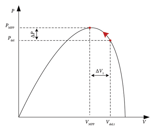
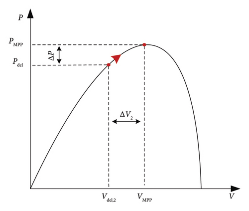
During a lack of power at the production level, the PV system operates in the MPPT mode. In contrast, if the power generated by the PV system is more than the demand, the PV plant or a partial PV plant will operate in deloading mode. Figure 12 illustrates the deloading method diagram.

The droop controller detects frequency errors. Δf and calculates the power error ΔP. The power error ΔP will be added to Pdel. Then, the P-U curve block regulates the DC voltage corresponding to the new power deloaded Pdel. Finally, the PI regulation generates the direct current id to command the DC bus. The P-U curve must be precisely set to make the system work perfectly.
4.1.2. For Wind Power Plants
As in PV systems, WTs also operate, generally, in the MPPT mode. To give the system a power reserve and the ability to respond to frequency variations, the deloading method could be utilized [84]. Two operation possibilities for the deloading method with wind power generator technologies are presented [85]. Pitch angle control: It is based on the variation of the pitch angle β (rotor blade angle) between two angles β0 and β1 to adjust the active power output Pdel with a constant rotor speed ΩMPP to finally give the system power reserve (see Figure 13) [86].
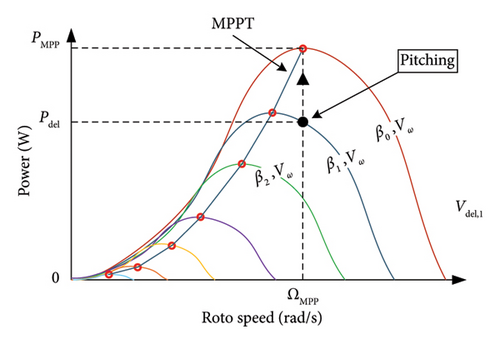
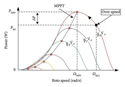
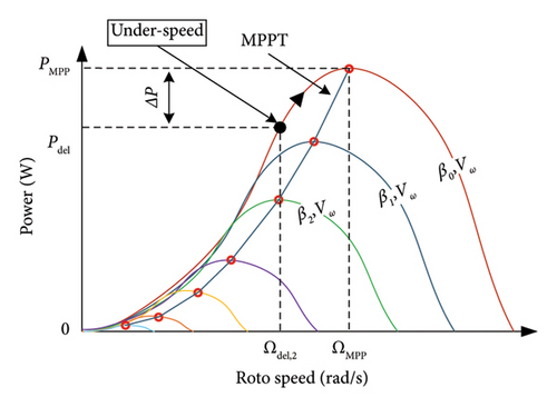
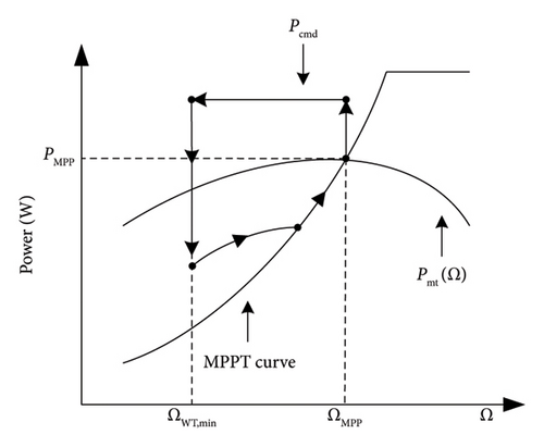
Speed control: It consists of varying the rotor speed to change the active power position from PMPP to Pdel with a fixed pitch angle β0. As illustrated in Figure 14, two distinct strategies are employed in the speed control technique. The first strategy, designated as “under speed control” (Figure 14(b)), is not recommended due to its potential adverse impact on stability. The second strategy, referred to as “over speed control” (Figure 14(a)), is considered more optimal [87, 88].
- •
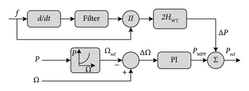
One-loop control: It is based only on the RoCoF. Equation (8) represents the inertial power generated with this technique. Pinertia, ωg, and H are the inertial power, grid angular frequency, and inertia constant, respectively. Figure 15(a) illustrates its diagram scheme. This control strategy does not have the ability to make the frequency return to its initial value f0 and this is its major drawback.
() - •
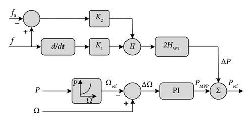
Two-loop control: It is based on both RoCoF and frequency deviation Δf. This control strategy is faster and gives the system the ability to make the frequency return to its initial value f0. Equation (9) and Figure 15(b) represent the inertial power of the two-loop control strategy and its diagram, respectively.
() -
where KI is the inertia gain and Kdroop is the drooping gain.
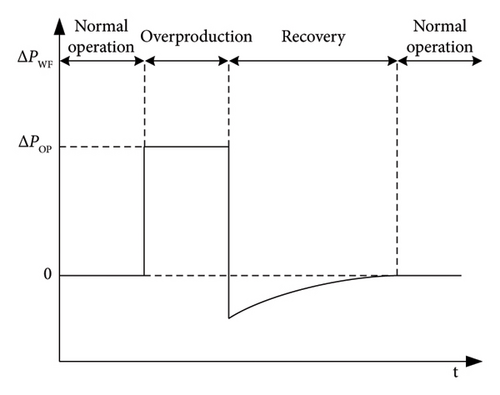
For the sake of comparison, the variable speed WT absorbs and releases a significantly higher amount of kinetic energy stored in the rotor than fixed WTs, and it does so at an accelerated rate.
4.2. Inducverters
Inducverter is a technique to emulate grid inertia. The inducverter imitates the induction machine, especially its inertia characteristics [94]. It is known that the induction machine has self and soft start capability and also its automatic synchronization with the grid without the need of PLL. The inducverter utilizes these characteristics to regulate active power and frequency by the exploitation of the virtual rotor inertia of a power electronic inverter.
An inducverter is a combination of an inverter with a filter and control command that makes the inverter behave as an induction machine. Figure 17 shows the control diagram of the inducverter. As it is observed, the control section is composed of two major parts: (i) the current/power damping/synchronizing unit and (ii) the control core. The current/power damping and synchronizing unit enables the inducverter to achieve self-start and soft-start by generating the reference frequency, ensuring smooth, and automatic synchronization with the grid.
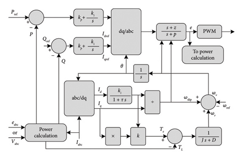
The active and reactive power references are regulated by a PI regulation, and the voltage reference applied to the pulse-width modulation (PWM) is generated by the adaptive virtual lead or leg impedance/compensator block. This topology is simple and no PLL is needed. However, the open loop of voltage and current control makes the inducverter generate an undesirable transient during large disturbance. In addition, the inducverter is unable to provide fast-fault current because its power is kept constant regardless of grid variations. The inducverter was not investigated in an islanded operation yet. But overall, in a high penetration of the RESs, this technique of inertia control could give a big help to the grid [94].
4.3. Synchronverters
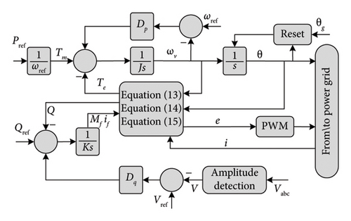
From the control diagram, we see the two major loops in synchronverter, frequency drooping loop and voltage drooping loop. The frequency drooping loop is related to the frequency changes like in SG and it is responsible for managing the power output. In the frequency drooping loop, the difference between angular frequency reference ωref (which is equal to the nominal angular frequency of the grid ωg) and the virtual angular speed ωv is calculated and multiplied by the damping factor DP and then added to the mechanical torque Tm (Tm is obtained from the reference active power Pref). The result is compared with the electromagnetic torque Te which is calculated by (12) and finally divided by the moment of inertia J.
In the voltage drooping loop, the tracking error between the reference reactive power Qref and the reactive power Q that is calculated by (15) is added to the result of the multiplication of DP and the difference between the reference voltage Vref and grid voltage Vg as mentioned in Figure 18. Then the resulting signal is multiplied by the gain 1/K to obtain the excitation flux. In the end, it is possible to calculate and generate (e) by (14) and apply it to the PWM for generating the switching signals.
4.4. Power Synchronization Controller
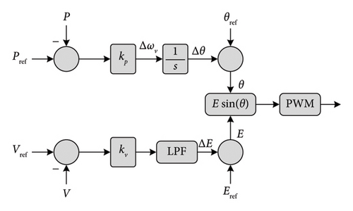
This topology is weak facing an over-current event and it has a large steady-state error due to the absence of the current control loop. However, in [97, 98], the authors added a current control loop to the system and performed it in a weak grid operation and fault ride through (FRT) capability. The purpose of FRT is to enhance the stability and reliability of the electrical grid, as well as to ensure the uninterrupted supply of electricity to consumers, even when the grid experiences minor disturbances [99]. For example, if there is a sudden drop in voltage due to a fault in the grid, a power generation system with FRT capability will adjust its operation to ride through the fault without disconnecting from the grid.
4.5. Synchronous Voltage Controller (Sync VC)
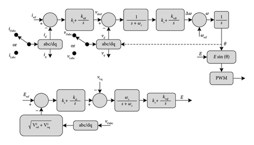
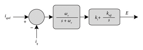
Figure 20 shows the diagram of Sync VC. In the d-axis, the current error (idref − id) is treated by a PI controller which gives Vref. Then Vdref − Vd is calculated and passes in a virtual PLL to generate the phase angle. The low-pass filter (LPF) 1/(s + ωv) is equivalent to 1/Js + DP and plays the role of the virtual rotor. So, it generates virtual inertia, damping effect, and attenuating PWM switching effects as the first objective. The q-axis control loop plays the role of the automatic voltage controller (automatic voltage regulation (AVR)) (see Figures 20(a), 20(b), and 20(c)). As a result, two operation modes are possible: (i) constant reactive power control mode id − Q bus, for maintaining constant reactive power to the feeder, and (ii) constant voltage control mode id − V bus, for maintaining constant voltage to the feeder. In the first mode id − Q, the error (iref − Q) passes in an LPF and then regulated by a PI control to adjust the voltage amplitude of the Sync VC. The second mode (id − V) is composed of a cascade of double loops where the first loop controls the feeder voltage amplitude and the second controls the q-axis voltage. The LPF 1/(s + ωr) is equivalent to 1/(sLf + Rf) and mimics the dynamic RL excitation circuit.

4.6. Fifth-Order VSM Topology
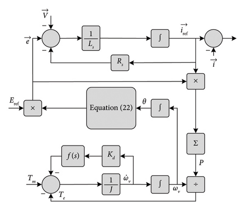
The 5th-order VSM takes the three-phase voltage V as its input and produces the three-phase current i as its output. The measured voltage grid is the input of the control circuit that generates the reference current iref. The inverter’s input is generated from the hysteresis by tracking the current error between iref and the measured current i and then passing by the PWM. The regulating mechanical torque is responsible for regulating and controlling the active power. However, the reactive power generated by the system is not controlled but it is adjusted by the grid’s SGs. This technique allows bidirectional power flow which is suitable for energy power storage systems such as ESSs.
4.7. VSM With Low-Order Model
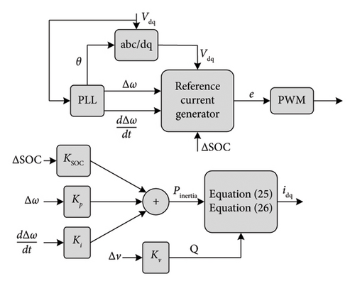
4.8. VSM0H
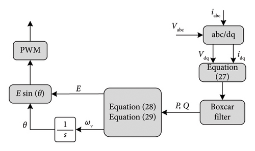
The active and reactive power are determined using Idq and Vdq, after which they are processed through a Boxcar filter. After one cycle, the frequency and voltage are calculated. The signal is then fed into the inverter through a PWM process. This technique enhances the natural damping in a SG and a VSM-dominated grid. This technique does not have inertia, so it could not react properly with the RoCoF but it is fast and could well manage the frequency nadir. The VSM0H has the ability of operating in a grid of 100% RES penetration, so it could perfectly work with the deloading method.
4.9. Universal VSM
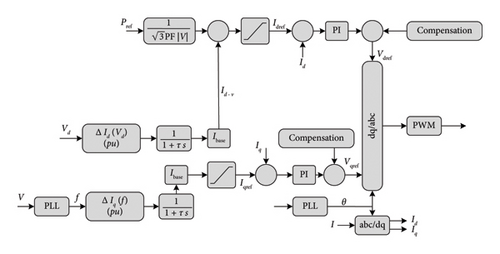
From Figure 24, the frequency regulation is assured by the virtual governor in proportion to Iq. However, the voltage is regulated by the AVR in proportion to Id−v.
4.10. ISE Lab VSM
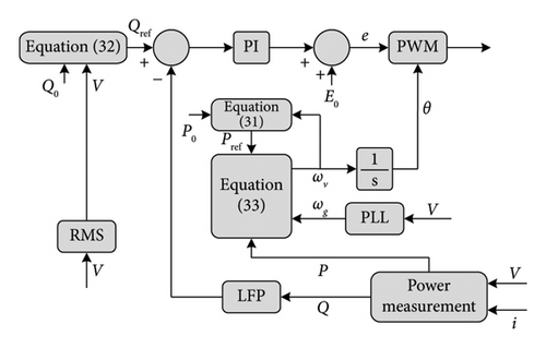
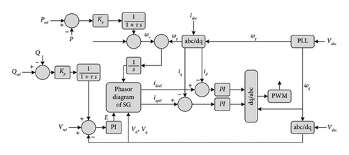
4.11. Algebraic Model of VSM
Equations (34) and (35) represent the dynamics of governor and AVR, respectively, and the diagram of the algebraic model of VSM is illustrated in Figure 26.
4.12. Discussion
- 1.
Seamless operation in grid-connected and islanded mode: One of the fundamental requirements for VSMs is the ability to seamlessly transition between grid-connected and islanded (standalone) modes of operation. This capability ensures the uninterrupted supply of power even when the grid experiences disruptions or faults.
- 2.
Inherent over-current protection: VSMs should incorporate inherent over-current protection mechanisms to safeguard the system against excessive current flow, which can lead to equipment damage or grid instability.
- 3.
Dynamic voltage and frequency support: VSMs must possess the capability to provide dynamic support for grid voltage and frequency. They should be able to adjust their operating parameters to help regulate and stabilize voltage and frequency during transient disturbances.
- 4.
FRT capability: FRT, as mentioned earlier, is crucial for VSMs. It enables them to withstand and remain connected to the grid during short-term voltage or frequency disturbances, contributing to grid stability and reliability. Different regions and grid operators may have specific FRT requirements and standards that RE systems must adhere to, depending on the local grid conditions and regulations. These standards specify the performance and behavior of RE systems during grid disturbances to maintain grid stability and reliability.
- 5.
Black-start capability: Black-start capability is essential for power generation systems, including VSMs, to initiate and restore grid operations from a blackout condition. It ensures the ability to restart and synchronize with the grid when necessary.
When assessing various VSM topologies, it becomes evident that different topologies offer different features and capabilities.
Frequency support: All VSM topologies provide frequency support, which is a primary function of VSMs in emulating the behavior of SGs.
Voltage control/AVR: While all topologies incorporate some form of closed-loop control for voltage regulation and AVR, low-order VSMs typically do not include AVR functionality.
Seamless operation: Among the discussed topologies, only the universal VSM offers seamless operation in both grid-connected and islanded modes, making it suitable for a wider range of applications.
Over-current protection: Some topologies, such as the ISE Lab VSM and VSM0H, lack inherent over-current protection, which may necessitate additional protective measures.
FRT and frequency detection: Each topology exhibits unique characteristics when it comes to FRT and frequency detection. These distinctions can influence their suitability for specific grid conditions and requirements.
In conclusion, selecting the most suitable VSM topology requires careful alignment with the grid’s specific needs and operational conditions. Each VSM topology offers distinct advantages and limitations, making it crucial to evaluate them against technical requirements, such as response time, stability, and compatibility with existing infrastructure. By thoroughly assessing these factors, grid operators can make informed decisions that enhance grid stability and performance in high-RES environments. Table 5 provides a summary of the FRT and frequency detection characteristics, as well as the major advantages and drawbacks of each topology, aiding in the selection process for the most suitable VSM topology based on specific grid scenarios and operational requirements.
| VSM topology | Frequency detection | FRT | Advantage | Drawback | References |
|---|---|---|---|---|---|
| Inducverter | Yes | Yes | Soft-synchronizing and autosynchronizing capability | Limited fast-fault current injection | [94] |
| Synchronverters | Yes | Yes | The same dynamics as SG observed from the grid | Numerical instability | [113–116] |
| Power synchronization controller | Yes | Yes | Emulates the self-synchronizing capability of SGs | Large steady-state error | [96, 117, 118] |
| Synchronous voltage controller | Yes | Not investigated | Emulates SG dynamics in voltage loop | Instability during fault | [100] |
| 5th-order VSM | No | Not investigated | Fast employments | Numerical instability | [119, 120] |
| Low-order VSM | Yes | Not investigated | PLL emulation of the SG’s swing equation | Susceptible to noise from frequency derivative term | [107, 121–123] |
| Virtual synchronous machine zero inertia | No | Not investigated | Simple control structure | No inherent over-current protection | [124, 125] |
| Universal VSM | Yes | Yes | Seamless operation in all operating modes | No experimental validation | [105, 126, 127] |
| ISE Lab VSM | No | Yes | Simpler replication of SG dynamics | Power oscillations | [128] |
| Algebraic model of VSM | Yes | Not investigated | Phasor’s representation of the SG | Need to change the control paradigm between grid and islanded modes | [109] |
5. Some Issues of Inertia Implementation
In this field of research, there exist diverse challenges, mechanisms for modeling, and prospects for incorporating RES [129]. Adequate comprehension of these challenges is essential to progress in this sphere. Some stochastic frameworks to model inertia and power frequency response support are presented in [130–132]. Implementing VSMs and enhancing inertia presents several technical challenges, which are discussed in this section.
5.1. Time Delays
In theory, there is no time delay in power converters and power control to respond and deliver power to the grid [133]. However, in practice, a communication and power conversion time delay is introduced, which could cause a bad functioning of the frequency control system and destabilize the entire system [134]. The time delay is caused by communications and power control of the power converter [135].
5.1.1. Communication Time Delay
It is the time of transmissions between the control center and power converters. Optimizing the distance between control centers and power converters is essential. In large power systems, a decentralized approach, as proposed in [136], may be more effective. But in practice, it still exists and it must be considered in system dimensioning [137].
5.1.2. Power Control of Individual Power Converter Time Delay
It is the time needed to switch between modes, e.g., from deloading mode to MPPT mode. Some techniques and schemes were proposed to reduce it [136]. The utilization of ESSs is one of the most effective solutions. However, it has other concerns like the high cost and life cycle [138].
5.2. Placement of Inertia
Time-varying inertia profiles and locations of inertia may have a big impact on a large power system. One of the most important concerns of the utilization of ESSs is their placements [139]. The optimal placement of ESS units is a big challenge to the inertia emulation system. Reference [140] proposed an optimization program based on the maximization of the damping ratio of every power system mode and minimizing the oscillation between generators.
5.3. Adaptive Inertia
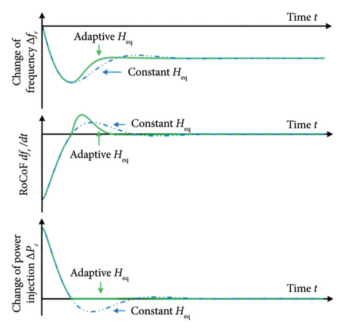
In a power grid, frequency deviations and the RoCoF are not constant during frequency events. Therefore, inertia should also vary to ensure an appropriate response. Figure 27 [17] presents a comparison between adaptive and constant inertia during a frequency event. Additionally, studies [149] and [150] propose control system schemes that achieve fast frequency recovery with reduced oscillations. These control systems emulate inertia according to frequency deviations and RoCoF. An algorithm for searching continuously the optimal inertia is presented in [143]. The main drawback of these algorithms is the nonlinearity of the adaptive inertia which causes a negative impact on the stability of the power grid [144].
5.4. Market Design for Inertia Service
Nowadays, inertia is not considered an extremely important property in the majority of power systems. That is what makes the inertia emulation still an experimental field [145]. So, the market of inertia emulation needs to be well-designed and optimized to integrate it and make it function perfectly [146]. Considering inertia as a frequency regulation control ancillary service will highly help the integration of inertia emulation market in the power system. In addition, the compatibility of inertia ancillary service with the other ancillary services is highly required.
6. AI as a Solution to Enhance Inertia
AI is pervading all fields of human activities. In addition, the power grid is going to be more intelligent for managing all the new sources and load characteristics. AI has the ability to predict stability issues and different perturbations in the power system [147]. Furthermore, the drawbacks of some VSM topologies and problems could be solved. To reach the sustainable development of society, RESs are considered the unique solution [17]. So, to manage all the challenges that come with it, the grid must be more intelligent in all its sectors from generation to consumption. As a result, AI can give a good help and a huge step for the smart grid.
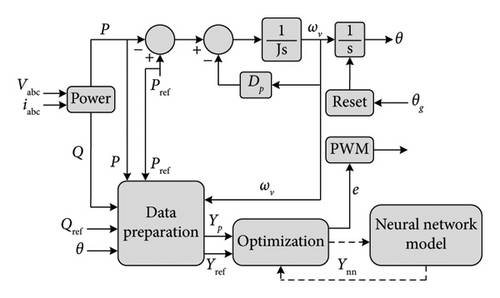
X, F, U, and Y are the state vector, the derivative state vector, the input vector, and the output vector, respectively. G is the output vector in terms of the input vector.
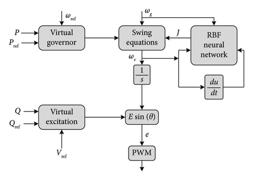
A radial basis function (RBF) to improve frequency stability and overcome the shortcomings of VSMs is presented in [149]. This system determines the VSM stability margin, frequency adjustment time, power circuit cutoff frequency, grid connection standards, the reasonable range of virtual inertia J, and the damping coefficient DP. The proposed RBF NN has one hidden layer based on the Gauss function. This AI system is designed to determine the virtual inertia J. So, the control block diagram (see Figure 29) has J as an output. The instantaneous angular velocity ω and its derivative (dω/dt) are the input vector.

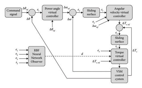
As renewable integration continues, the relevance of AI-based solutions will grow, allowing for predictive and real-time adjustments in VSM control and ESS discharge. The SWOT analysis (see Table 6) highlighted that while AI offers adaptability and precision, it introduces challenges related to resource intensity (high computational, energy, and financial demands), as well as cybersecurity concerns, necessitating further study.
| SWOT analysis of AI solutions | ||
|---|---|---|
| Internal factors |
|
|
| External factors |
|
|
7. Practical Case Studies and Applications
The inertia enhancement strategies discussed in this review, including VSMs, ESSs, SCs, and WTs, are not merely theoretical, they are currently employed in power grids worldwide. These methods are vital for maintaining stability in grids with high levels of RES integration. However, as RES penetration increases, the requirements for these systems grow, creating the need for faster and more precise control. In this context, AI emerges as a revolutionary solution, offering predictive capabilities and rapid response times that traditional control methods struggle to match.
The following case studies present existing inertia solutions and illustrate how AI could further enhance these applications through improved real-time control and forecasting.
7.1. Case Study 1: Denmark’s High-RES Grid With SCs and WTs
Denmark’s Western Power Grid, which connects to Norway, Sweden, and Germany, has a high integration of RE, predominantly wind, leading to a system with low inertia. This configuration presents frequency stability challenges, particularly during disturbances. To counter frequency instability resulting from high-RES penetration, SCs are strategically placed. These SCs help support rotational inertia by either injecting or absorbing energy to stabilize frequency during disruptions. For instance, when a generator disconnects, SCs release rotational energy to slow the frequency drop. Similarly, during periods of excess power, SCs absorb energy to prevent frequency rise, thus supporting system stability. Simulations indicate that adding SCs raised the frequency nadir from 49.35 Hz to 49.5 Hz under specific disturbance conditions [152].
This case study demonstrates that while SCs enhance stability, system complexity increases with greater RES integration. AI integration would enable scalability, allowing for enhanced real-time and predictive control. By forecasting frequency fluctuations and dynamically adjusting SC and turbine outputs, AI could enhance the reliability of Denmark’s grid, advancing it toward a more resilient and intelligent future.
7.2. Case Study 2: Great Britain’s National Grid With VSMs and Battery ESSs
Great Britain’s National Grid employs VSMs and battery-based ESSs to counteract the inertia loss due to RES integration. The VSMs are optimally tuned with specific damping and droop settings to simulate synchronous inertia, while battery ESSs provide rapid frequency response by discharging during grid disturbances. This combined approach has notably enhanced grid resilience, underscoring the benefits of integrating VSMs and ESSs for inertia support.
Recent modifications to the balancing mechanism (BM) have amplified battery ESS roles in maintaining grid stability, leading to a 47% increase in battery dispatch across the network. This increase follows the National Grid ESO’s reintroduction of bulk dispatch for battery units, enabling multiple batteries to be dispatched simultaneously. Previously, units with higher-rated power were prioritized for ease of dispatch, but bulk dispatch now allows proportional participation of all battery units, increasing the grid’s flexibility and responsiveness [153].
AI integration could further transform battery ESS operation and grid stability. Predictive AI algorithms could enable ESS units to anticipate demand peaks or RES output variations, facilitating proactive energy dispatch that minimizes curtailment and maximizes grid support. For instance, AI could predict grid stress events and coordinate ESS discharges to preemptively stabilize frequency, optimizing battery utilization across multiple assets in real time. Furthermore, AI could improve market responsiveness by analyzing price signals and dynamically adjusting ESS dispatch in line with real-time grid conditions and historical demand data, enabling operators to capitalize on high-value opportunities while balancing supply and demand [154].
7.3. Case Study 3: California’s High Solar Penetration and ESS Integration
In California, high solar penetration has necessitated extensive ESS deployment to prevent overgeneration and support grid stability [155]. Solar output often exceeds demand, particularly during midday in spring and fall. ESS thus plays a critical role in preventing solar power curtailment by storing excess energy and discharging it during peak demand periods. These battery ESSs provide synthetic inertia, discharging rapidly to stabilize frequency during load variations and mitigating reverse power flow common in high-penetration PV scenarios [156].
To handle solar variability and improve grid flexibility, the Los Angeles Department of Water and Power (LADWP) has deployed large-scale battery systems and pumped hydro storage, supporting load leveling, peak shaving, and frequency regulation, all crucial for managing solar power’s intermittency [157]. Research by Southern California Edison highlights the role of ESS in voltage regulation, which helps California’s grid accommodate increasing PV penetration more effectively by stabilizing frequency [156].
AI integration within California’s ESS framework holds the potential to enhance these capabilities. AI-driven predictive algorithms can optimize ESS discharge and charge cycles based on real-time grid status and demand forecasts. By anticipating periods of high solar output or demand, AI can dynamically adjust ESS operations, thereby improving frequency stabilization and reducing curtailment reliance. AI can also enable advanced demand response (DR) by coordinating distributed ESS units to autonomously address grid disturbances, supporting both voltage and frequency regulation. This approach not only reduces grid instability risks but also extends ESS lifespan by optimizing usage patterns.
These cases demonstrate that while inertia enhancement methods are widely implemented, the demand for stability in high-RES grids calls for advanced solutions like AI. With predictive control and rapid response capabilities, AI is well-positioned to become a critical component of inertia management. Gradually implementing AI-driven solutions will contribute to the development of smart grids. In this way, AI not only addresses current inertia needs but also establishes a foundation for resilient, intelligent power grids aligned with a sustainable, smart energy vision. Inertia enhancement techniques are also highly complementary to grid modernization efforts, such as smart grids and DR programs, which provide the real-time adaptability and infrastructure needed to integrate AI with existing grid assets.
Smart grids enable real-time monitoring and adaptive control of grid resources, facilitating inertia emulation through VSMs, ESSs, and advanced control algorithms. VSMs, for instance, can be managed via smart grid communication protocols to emulate inertia based on real-time grid conditions. DR programs help manage load during frequency disturbances by reducing or shifting demand to balance generation and load, indirectly supporting grid inertia. Smart grids provide the communication infrastructure necessary to coordinate various inertia sources, while DR can react to rapid frequency changes, reducing the need for high physical inertia. Together, these advancements ensure that both generation and load respond to grid conditions, enabling a more flexible and resilient power system.
8. Conclusion
This comprehensive review analyzes inertia enhancement strategies for high-RES power grids, emphasizing the growing need for stability and adaptability. By examining VSMs, ESSs, WTs, and SCs, the study sheds light on each method’s technical capabilities and limitations. Key among the contributions is the forward-looking perspective on integrating AI to optimize inertia emulation, offering benefits in predictive and real-time control not attainable through traditional approaches. Practical case studies throughout the review illustrate how these techniques are already applied in high-RES power systems, and a comparative analysis of VSM topologies provides a clear reference for practitioners selecting the most suitable methods.
The study concludes that as RES penetration intensifies, so does the need for intelligent, responsive solutions. AI integration is positioned as a critical enabler, enhancing VSM and ESS applications by predicting grid fluctuations and dynamically adapting system responses to improve stability. Future research directions may focus on developing adaptive AI-driven VSM controllers for real-time response and exploring hybrid inertia solutions to further enhance resilience. These insights align with global sustainability goals and pave the way for designing intelligent, robust power grids capable of meeting the complex demands of a decentralized, RE landscape.
Nomenclature
-
- Ekin
-
- The kinetic energy [J]
-
- ωr
-
- The rated velocity of the rotor [m/s]
-
- J
-
- The moment of inertia [kg·m2]
-
- Hgen
-
- The power system’s global inertia [s]
-
- Hsys
-
- The inertia constant of the system [s]
-
- fnom
-
- The nominal frequency [Hz]
-
- Hgen
-
- The inertia constant of the generator [s]
-
- Sgen
-
- The rated power of the synchronous generator SG [VA]
-
- Ssys
-
- The rated power of all the system [VA]
-
- Egen
-
- The kinetic energy of the SG [J]
-
- Vcdc
-
- DC-link voltage [V]
-
- Ccdc
-
- DC-link capacitance [F]
-
- ωr
-
- Rotor angular frequency [rad/s]
-
- Vdel
-
- Voltage deloaded [V]
-
- VMPP
-
- The voltage at the maximum power point [V]
-
- Δf
-
- Frequency error [Hz]
-
- ΔP
-
- Power error [W]
-
- Pinertia
-
- Inertial power [W]
-
- ωg
-
- Grid angular frequency [rad/s]
-
- H
-
- Inertia constant [s]
-
- Tm
-
- The mechanical torque [N.m]
-
- Te
-
- Electrical torque [N.m]
-
- Dp
-
- Damping coefficient
-
- ωv
-
- Virtual angular frequency [rad/s]
-
- ωslip
-
- Slip frequency [rad/s]
-
- θ
-
- Phase angle [rad]
-
- P
-
- Active power [W]
-
- Pref
-
- Active power reference [W]
-
- Q
-
- Reactive power [VAR]
-
- Qref
-
- Reactive power reference [VAR]
-
- Mf
-
- Maximum mutual inductance [H]
-
- Vg
-
- Grid voltage [V]
-
- Rs
-
- Stator resistance [Ω]
-
- Ls
-
- Stator inductance [H]
-
- ΔSOC
-
- State of charge deviation [W]
-
- KSOC
-
- State of charge gain [W]
-
- τs
-
- Time constant [s]
Conflicts of Interest
The authors declare no conflicts of interest.
Funding
No funding was received.
Open Research
Data Availability Statement
The data that support the findings of this study are available from the corresponding author upon reasonable request.


