Design and Application of Noncircular Superimposed Gear
Abstract
To address the issue of seedling precision affected by transmission errors resulting from tooth backlash in the seedling pickup process, this study presented a novel solution by introducing a design method for a noncircular superimposed gear (NCSG). The influence of the different numbers of NCSG slices on meshing line length and contact ratio was analyzed. The NCSG was manufactured using wire-cutting technology, and a transmission ratio measurement experiment was performed. In comparison with theoretical data, simulated data, and experimental data, it was found that the three were basically consistent. Furthermore, the NCSG was applied in the seedling pickup mechanism of the planetary gear train. The observed seedling pickup trajectory matched the simulated trajectory. To validate the performance of the mechanism prototype, a seedling pickup experiment was conducted on the seedling pickup mechanism of the NCSG planetary gear train. The success rate of seedling pickup is over 93%, demonstrating the mechanism’s effectiveness.
1. Introduction
Gear transmission is a prevalent form of transmission in mechanical transmission. General gears are round gears. When the mechanism needs variable speed ratio transmission, round gears can no longer meet transmission requirements, but noncircular gears can achieve two-axis variable speed ratio transmission. At the same time, noncircular gears have the advantages of gears and cams and can accurately achieve instantaneous transmission ratios. Noncircular gears have been widely used in agriculture, light industry, and other fields, such as rice transplanters, textile machinery, medical, and aviation [1].
Regarding research on large contact ratio gears, Ahmed et al. [2] proposed a design method for noninvolute spur gears with high contact ratios, which have smaller sliding contacts and better lubrication conditions than traditional high contact ratio gears. Marimuthu and Muthuveerappan [3] designed a nonstandard asymmetric spur gear with a high contact ratio using the direct gear design method, which has a higher bearing capacity than traditional spur gears with high contact ratios. Staph [4] proposed a design method for low and high contact ratio involute gears, which generate high contact ratio gears by increasing the addendum heights of low contact ratio gears. Prabhu Sekar and Muthuveerappan [5] designed asymmetric gears, which not only can reduce gear weights and sizes but also improve gear-bearing capacities. Fujikawa et al. [6] developed and fabricated a pair of spur gears with an asymmetric tooth profile, aiming for a high contact ratio by increasing tooth depth, which reduces gear transmission vibration and noise. Podzharov et al. [7] presented a design method for achieving high contact ratio gears using a standard gear cutter. Experimental verification demonstrated that high contact ratio gears exhibit lower static and dynamic transmission errors when compared to standard gears. Wang et al. [8] proposed an active design method of high contact ratio gears on the basis of pressure angle. Compared with involute gears with the same parameters, high contact ratio gears have the advantages of large contact ratios, small sliding coefficients, and minor maximum contact stress levels, which are beneficial to improve gear wear and gear life. Tang et al. [9] proposed a new type of tooth profile gear with a high contact ratio, small force, and high bearing capacity and analyzed its stress. Yu et al. [10] proposed a high contact ratio transmission system comprising double-row external meshing involute spur gears with staggered half pitches. This transmission system improves the contact ratio compared with the spur gear and reduces the vibration impact generated during the gear transmission process. M. Tsai and Y. Tsai [11] proposed a method for designing spur gears with high contact ratios using secondary parametric tooth profiles. A simplified mathematical model for parametric tooth profiles was derived by the authors. Chen et al. [12] proposed an internal meshing gear with a circular tooth profile and involute tooth profile on the basis of the design of the meshing line function, which reduces gear transmission noise and vibration and increases gear endurance and life. Xu et al. [13] conducted an investigation on the tooth profile design for a novel internal meshing gear transmission with a high contact ratio, high stiffness, and high transmission efficiency. Su et al. [14] proposed a new design method of a high contact ratio of contact path along the tooth length direction, which improves the meshing performance of helical bevel gear and the tooth strength and surface contact strength and reduces the gear transmission error. Our research group [15–17] proposed a design method for an involute–cycloid noncircular gear, which is used to solve the undercut of an involute tooth profile with a small curvature radius of a noncircular pitch curve. We applied this method to the planetary seedling pickup mechanism. To enhance seedling pickup precision and reduce tooth backlash, we proposed a design methodology that incorporates an involute-variable cycloid. We also proposed a tooth profile design method of an involute–incomplete cycloid to address the design challenge associated with noncircular gears having cusp pitch curves.
Scholars at home and abroad have investigated the seedling pickup mechanism. Choi et al. [18] developed a slide-type seedling pickup mechanism driven by a multilink mechanism where the rocker and the slide control the position and posture of the seedling pickup needle. The seedling pickup efficiency is 40 plants/min, and the success rate is 97%, but the seedling pickup efficiency of the seedling pickup method is low. Iqbal [19] developed a linkage-combined single-arm seedling pickup mechanism, but the mechanism must improve its slow seedling pickup speed and low efficiency. Perez-Ruiz and Slaughter [20] developed a precision three-row synchronous transplanting machine, but it requires manual seedling throwing and has low efficiency. Pandirwar et al. [21] developed a six-row semiautomatic rice transplanter, but the mechanism requires manual seedling feeding and has low work efficiency. Tsuga et al. [22] designed an automatic vegetable transplanting machine with gear transmission and a connecting rod slider. The mechanism efficiency is 50 plants/min, the efficiency is low, and the slider is easy to damage. Cui et al. [23] proposed a second-order elliptic planetary gear train seedling pickup mechanism and designed a double-row planetary gear mechanism to drive the seedling pickup claw. The working efficiency is 80 plants/min, and the success rate of seedling pickup is 91.3%. Tian et al. [24] designed a door-shaped seedling pickup mechanism composed of a guide rod and a profiling chute, which is not suitable for high-speed operation. Yuan et al. [25] designed an air-blowing vibration compound mechanism for seedling pickup, achieving a success rate of 92%. Liao et al. [26] designed an embedded pneumatic seedling pickup mechanism with an efficiency of 400 plants/min and a success rate of 93%. However, the mechanism has problems such as the cylinder motion impact, which causes pot seedlings to slip in advance. Our research group [27, 28] proposed a vegetable pot seedling pickup mechanism of an elliptical incomplete noncircular planetary gear train. The mechanism realized the required mechanism motion trajectory through the variable speed transmission among incomplete noncircular gears. The seedling pickup efficiency was 90 plants/min, and the success rate was 95%. An automatic seedling pickup mechanism for a vegetable pot seedling automatic transplanting machine was designed, which utilized an eccentric gear–noncircular gear planetary system. The kinematics model of the seedling pickup mechanism was established, and the mechanism parameters were optimized to achieve optimal performance. The seedling pickup efficiency could reach 90 plants/min, with a success rate of 95%.
Previous research found that the transmission error resulting from the clearance between the teeth in a noncircular gear significantly influences the error of the seedling pickup trajectory. To reduce the tooth backlash error, we used the helical gear transmission in the secondary transmission [29]. The design method of increasing the gear contact ratio reduces the transmission error resulting from tooth backlash, and the seedling pickup trajectory error is improved. However, the use of a noncircular spur gear in the first-stage transmission results in a low contact ratio. In theory, noncircular helical gears can be used to improve contact ratios in the first-stage gear transmission. However, the cost is high due to the difficulty of processing noncircular helical gears. We proposed a design method of noncircular superimposed gear (NCSG) to enhance the contact ratio of noncircular gear transmissions while minimizing the transmission error resulting from clearance. To improve the “compliance” of gear meshing (increase the “aspect ratio” of tooth profile: the ratio of the height of tooth profile to the width of tooth profile pitch curve), the involute tooth profile of a noncircular gear was designed by reducing the pressure angle of tooth profile. The NCSG design platform was developed. NCSG was implemented for the purpose of the seedling pickup mechanism in the planetary gear train with noncircular gears. The simulation analysis was conducted using virtual simulation software for the mechanism, and the seedling pickup prototype was trial-produced and verified through the seedling pickup experiment.
2. Design of NCSG
2.1. Principle of NCSG
The contact ratio of helical gear transmission is large, and the load of each pair of gears is small, which relatively improves the gear-bearing capacity. Compared with spur gear transmission, helical gear transmission is stable. This meshing method also reduces the influence of manufacturing error on transmission. Based on helical gear slicing, we proposed a design method for NCSG. On the same pitch curve, the starting points of the first pair of active wheels and driven wheels overlap. The starting point of the second driving gear tooth profile is 2, whereas that of the driven gear tooth profile is 2 ′. The starting point of the third driving gear tooth profile is 3, whereas that of the driven gear tooth profile is 3 ′. The starting point of the tooth profile of the driving and driven gear is staggered at different angles on the pitch curve. Two noncircular spur gears were superimposed. This study analyzed two and three NCSG pieces on the basis of their different stagger angles, as shown in Figure 1. The three-dimensional model is shown in Figure 2.


2.2. Helical Angle of NCSG
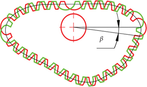
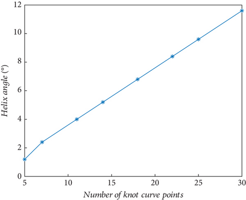
| Starting point of gear pitch curve/dimensionless | The helical angle corresponding to the starting point of the pitch curve (°) |
|---|---|
| 7 | 2.4 |
| 14 | 5.2 |
| 20 | 7.6 |
2.3. Development of NCSG Design Platform
According to the NCSG principle described in Section 2.1, the NCSG design and optimization software was developed using the GUI module of MATLAB software. The software development process is displayed in Figure 5.

Based on the human–computer interaction, parameters such as addendum height coefficient, tooth number, and clearance coefficient were adjusted to complete the NCSG design. The position of the cycloidal tooth profile was adjusted based on the undercutting position of the involute tooth profile. The cycloid tooth profile replaced the involute tooth profile with undercutting.
Figure 6 shows the human–computer interface of the NCSG design software. The interface can be divided into four parts: (1) pitch curve adjustment area, (2) gear parameter adjustment zone, (3) tooth profile display area, and (4) tooth profile starting point adjustment area.
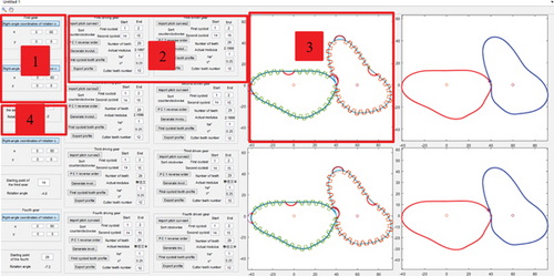
The adjustment area of the tooth profile starting point can input the tooth profile starting point of the i-th gear (i = 1, 2, 3⋯). Based on the same pitch curve, the tooth profile starting point of each noncircular gear is different so that each noncircular gear tooth can stagger a certain angle, equivalent to a noncircular helical gear in structure. The starting point of the last gear tooth profile determines the NCSG helical angle. The gear parameter adjustment area allows for the adjustment of parameters such as gear tooth number, addendum height coefficient, and top clearance coefficient. In the tooth profile display area, the tooth profile shape can be observed to determine whether the tooth profile meets the design requirements. The pitch curve adjustment area enables the adjustment of the rotation center of the pitch curve.
3. Analysis of NCSG
3.1. Contact Ratio Analysis of NCSG
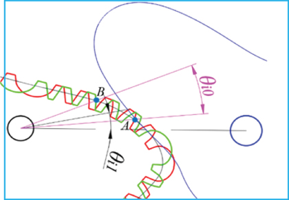
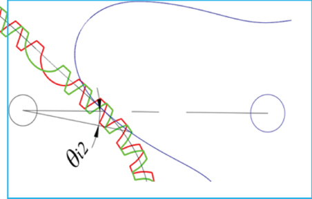
Figure 8 shows the contact ratio of two NCSG slices corresponding to different helical angles. With the increase of helical angle, the contact ratio of NCSG also increases. Figure 9 shows the corresponding relationship between helical angle and contact ratio increase. With the increase of helical angle, the contact ratio of NCSG is increasing.
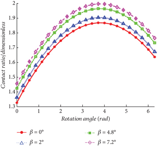
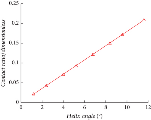
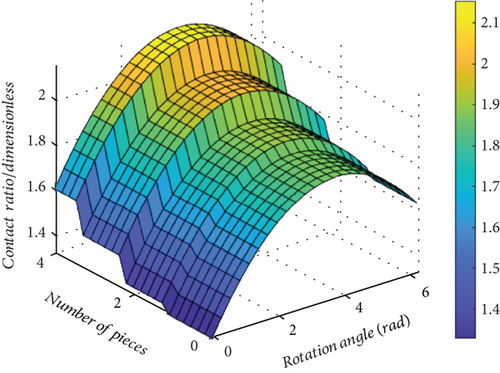
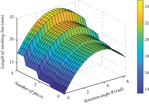
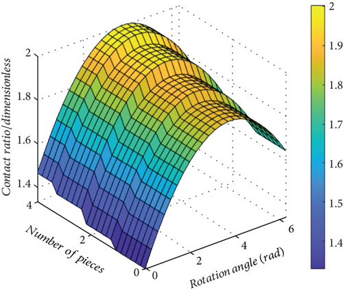
Figure 10a,b shows the impact of the number of NCSG slices on the contact ratio and meshing line length when each slice measures 3 mm. As illustrated in Figure 10, an increase in the number of NCSG slices results in a significant increase in contact ratio. Figure 10c,d discusses the influences of different numbers of NCSG slices on contact ratio when the total thickness of NCSG is 7 mm. As the number of slices increases, the NCSG contact ratio increases continuously, but the degree of increase is small. The analysis of the NCSG contact ratio shows that the minimum NCSG contact ratio is above 1.2, which can meet the transmission requirements and prove the feasibility of the NCSG design.

3.2. Contact Analysis of NCSG
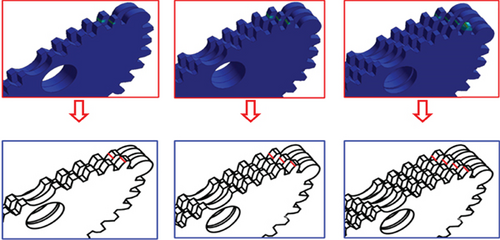
Figure 11 shows that the workbench finite element simulation verifies that the contact line length increases along with the number of NCSG slices and helical angle. The contact lines of different gears are several parallel lines.
4. Experiment of NCSG
4.1. Tooth Backlash Experiment of NCSG
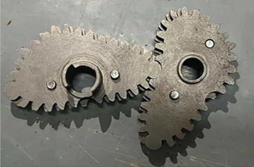
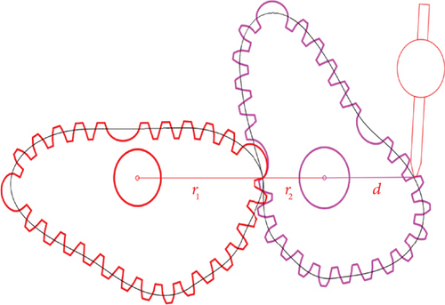
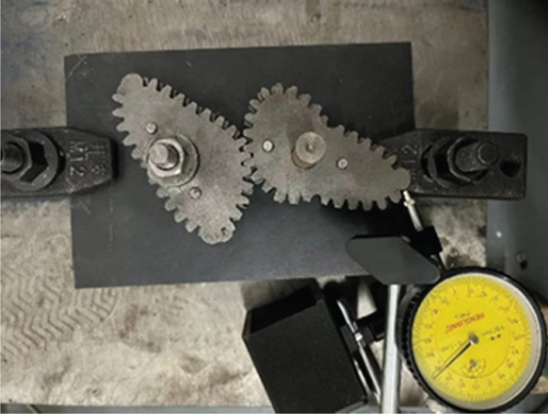
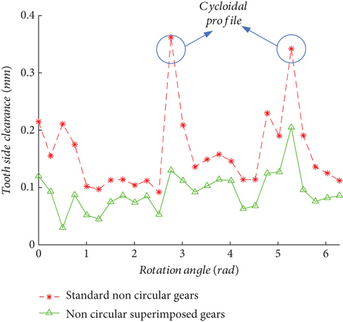
The number of NCSG teeth designed in this study is 26, and the average value of the tooth backlash of each tooth was taken as the actual tooth backlash after a five-time measurement. The two large tooth-side clearances were cycloidal tooth profile side clearances. Figure 15 illustrates that the tooth backlash of NCSG is smaller compared to the standard involute noncircular gear. The result proves that the superimposed gear design can reduce tooth backlash.
4.2. Transmission Experiment of NCSG
The gear transmission ratio experiment bench was built to carry out the transmission ratio experiment. The experiment instrument is shown in Table 2.
| Name | Model number |
|---|---|
| Angle transducer | P2022-V2-36 0-DQ |
| Dynamic torsion sensor | JN-DNI-50N.M |
| Asynchronous machine | 1.1KW-1400r/min-1.5 |
| Acquisition device | MLT16-SDAQ |
| Dynamic torsion measurement and control instrument | MCK-DN |
| Frequency converter | VCO BOP-2 |
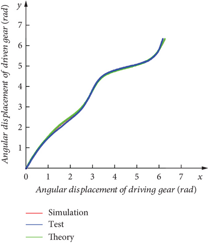
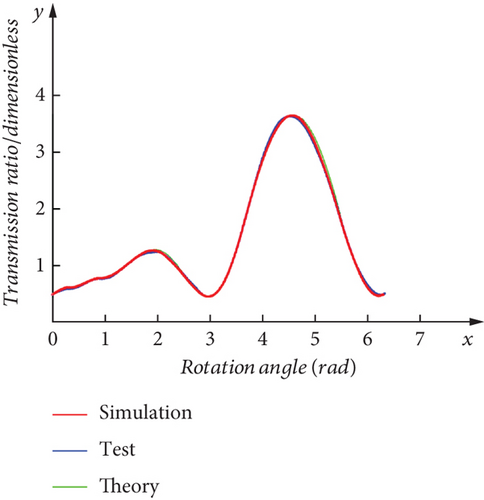
Figure 16 shows the NCSG transmission experiment, and virtual simulation software was utilized to simulate data for the transmission ratio and angular displacement. The simulation data was then compared to theoretical and experimental data, demonstrating the overall consistency among the three datasets, as illustrated in Figure 17. These findings provide evidence of the accuracy and validity of the NCSG design.

4.3. Experiment of Seedling Pickup Mechanism of NCSG Planetary Gear Train
4.3.1. Idling Experiment of Seedling Pickup Mechanism of NCSG Planetary Gear Train
NCSG was applied to the seedling pickup mechanism, as shown in Figure 18.
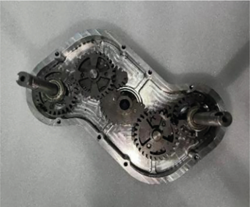
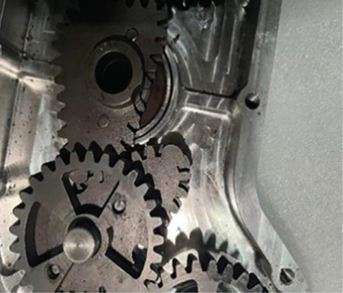
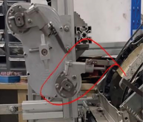
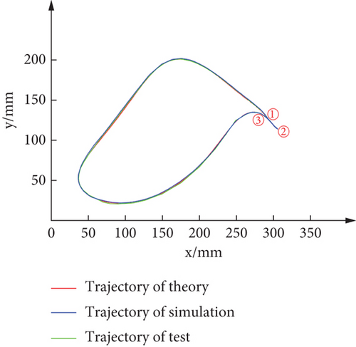
A virtual simulation of this mechanism was conducted using virtual simulation software to obtain a simulation trajectory. Assemble the seedling pickup mechanism and conduct idle running experiments to obtain the idle running trajectory. As shown in Figure 19, the trajectories of the three runs are essentially consistent, thus verifying the feasibility of the NCSG planetary seedling pickup mechanism.
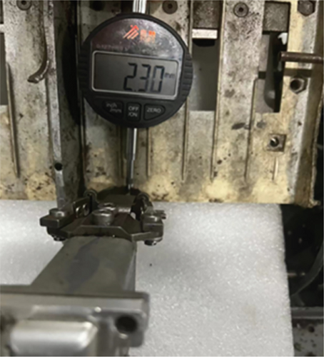
The shaking amount of the seedling pickup needle tip point in the seedling pickup stage directly affects the success rate of seedling pickup. The seedling pickup mechanism was adjusted to the position, and the dial indicator aligned with the seedling pickup needle tip point. Shaking the seedling pickup arm, the seedling pickup needle tip point error could be measured. The experiment is shown in Figure 20.
In Figure 21, the solid line indicates the error of the seedling pickup needle tip point of the standard noncircular gear seedling pickup mechanism, and the dotted line refers to the error of the seedling pickup needle tip point of the NCSG seedling pickup mechanism. Figure 21 also illustrates that the NCSG seedling pickup mechanism has a smaller error in its seedling pickup needle tip point at three positions than the standard noncircular gear, indicating that the NCSG design can reduce tooth backlash, thereby reducing the error of the seedling pickup needle tip point and improving the seedling pickup accuracy.

4.3.2. Seedling Pickup Experiment of Seedling Pickup Mechanism of NCSG Planetary Gear Train
The idling experiment was conducted to validate the correctness of the NCSG seedling pickup mechanism. The purpose of this experiment was to assess the applicability of the design seedling pickup mechanism. The seedling pickup experiment was conducted, as shown in Figure 22, in which Figures 22a, 22b, and 22c are the states of the seedling pickup, transportation, and pushing stage, respectively.
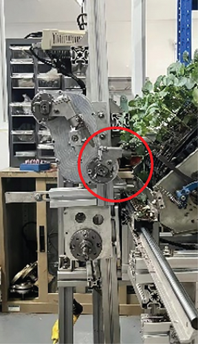
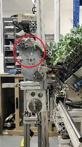
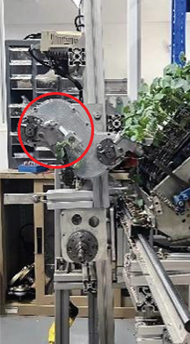
Table 3 shows that the success rates of seedling pickup at 20, 30, and 40 r/min were 96%, 94%, and 93%, respectively. As rotation speed increased, the success rate of seedling pickup decreased, but all of them were above 93%, which proved the practicability of the NCSG seedling pickup mechanism. The reasons for the seedling pickup and pushing failure in the seedling pickup experiment are mainly attributed to the following points: (1) Some pot seedlings have few roots, and the seedling pickup needle can only clamp part of the matrix when picking seedlings. (2) During the seedling pickup process, a seedling phenomenon occurs; that is, the seedling stems and leaves in the previous row or the next pothole are clamped by the seedling pickup needle, resulting in the hole phenomenon in the next seedling.
| Speed (r/min) | Total number of seedling taken | Seedling failure | Seedling success | The success rate of seedling collection |
|---|---|---|---|---|
| 20 | 100 | 4 | 96 | 96 |
| 30 | 100 | 6 | 94 | 94 |
| 40 | 100 | 7 | 93 | 93 |
5. Conclusion
- 1.
Built upon the concept of helical gear slicing, this study introduced a design method for NCSG with a high contact ratio. This approach was aimed at minimizing the impact of transmission errors caused by tooth backlash on the seedling pickup track and addressed the issue of up and down swing of the seedling pickup needle tip during the seedling pickup process.
- 2.
Dedicated software was developed for the design and optimization of NCSG, and gear contact ratio and meshing line length were analyzed. The NCSG was manufactured, and a transmission ratio experiment was conducted. The results obtained from theoretical calculations, simulations, and experimental measurements aligned closely.
- 3.
Furthermore, experiments were carried out to investigate tooth backlash for NCSG and measure the error of the seedling pickup needle tip point. The findings indicated that the NCSG tooth backlash and the error of the seedling pickup tip point were lower compared to noncircular spur gears.
- 4.
Apply NCSG to the seedling pickup mechanism and conduct experiments. High-speed cameras were utilized to capture idle trajectory data from the seedling pickup mechanism, and the observed trajectories were consistent with the theoretical and simulated trajectories. Seedling pickup experiments were performed on the mechanism, yielding a seedling pickup success rate of over 93% at three different speeds. These results further confirmed the practical viability of the designed NCSG seedling pickup mechanism.
Conflicts of Interest
The authors declare no conflicts of interest.
Funding
This work was supported by the National Natural Science Foundation of China (Nos. 32201676 and 52075497).
Acknowledgments
This work was supported by the National Natural Science Foundation of China (Nos. 32201676 and 52075497).
Open Research
Data Availability Statement
Data sharing is not applicable to this article as no datasets were generated or analyzed during the current study.


