Motion Characteristics Analysis and Realization of Hydraulic Drive Segment Assembly Machine
Abstract
For the current situation of the intelligence, the level of the segment assembly process was lower than it was expected. This paper took the 6-DOFs segment assembly machine designed by Shandong Jiaotong University and Jinan Heavy Industries Group Co., Ltd., as an example and specified the difference between the 6-DOFs segment assembly machine and common 6-DOFs mechanical arms. The core work of the paper contained two aspects. Firstly, the paper analyzed the kinematics mechanism and pointed out the mechanism characteristics of the segment assembly machine which was driven by six hydraulic cylinders and two hydraulic motors. Secondly, for the relationships between the joint rotative angles and the displacement of the driving hydraulic cylinders being more complex and intricate than they were expected, the paper illustrated the reason why there was no analytical solution for this mechanism and provided a simple method to obtain numerical solutions.
1. Introduction
Segment assembling machine is the key equipment for segment assembling in shield construction, whose function is to install the prefabricated segments on the surface of the newly excavated tunnel quickly and accurately [1]. The purpose of segment assembling is to prevent the infiltration of groundwater and subside of tunnel ground and then forms the permanent support for the tunnel. At present, the mechanization of segment hoisting, feeding, and assembling has been realized, but the level of intelligence is not enough. Therefore, the intelligent assembling work of the shield segment assembly machine is of great significance.
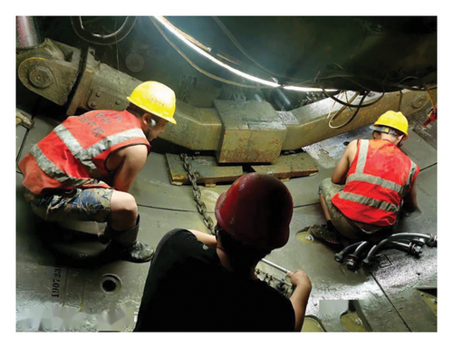
Academics and researchers had made many achievements in the intelligent control of segment assembly machines. Kosuge et al. proposed a force-position hybrid control algorithm suitable for segment assembly with the honey comb structure [2]. Kenji et al. proposed a segment assembly method which fitted for the installation of more than two types of segments [3]. WIRTH company proposed a vacuum suction cup segment assembly machine, which realized the automation of segment grabbing and splicing [4]. Fine-tuning mechanism [5, 6] and pioneering research utilizing laser sensing technology and virtual visual servo technology [7–10] also attracted the attention of many scholars. Research on segment assembly automation had obtained a lot of achievements, but those were not enough. At present, the segment assembly process still requires the cooperation of multiple people and tasks such as segment alignment and bolt tightening still depend on the handle remote control [10, 11]. Figure 1 shows the current construction process.
- •
The paper analyzed the mechanical structural features and proposed typical characteristics of the 6-DOFs segment assembly machine
- •
The paper analyzed the kinematics characteristics and gave the reason why there was no analytical solutions for the segment assembly machine
- •
A simple and practical kinematics modelling method was proposed and verified
The rest of this paper was organized as follows. Section 1 analyzed the characteristics of the mechanical structure; Section 2 analyzed the kinetic characteristics of the assembly machine and gave out the reason why the kinematics model of the segment assembler had no analytical solution; Section 3 proposed a simple and practical kinematics modelling method with the help of the cosimulation of MATLAB and ADAMS, and the validity and feasibility of the numerical relationships were tested by segment assembly experiments; Section 4 concluded the paper.
2. Mechanical Structure
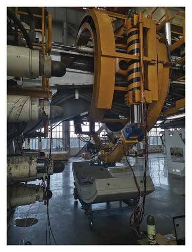
The mechanical structure of the segment assembly machine designed by Shandong Jiaotong University and Jinan Heavy Industries Group Co., Ltd., is shown in Figure 3. The rotary support frame and its attachments were driven by two identical hydraulic motors which have the same angular displacement. This mechanical configuration had three benefits. Firstly, system stability and reliability were improved; secondly, driving power was increased; thirdly, spare part cost could be decreased, in addition, if one of the two motor was failure, the other one could keep the segment assembly machine running. There were two hydraulic cylinders for lifting fixed on the rotary support frame and the two piston rods of the hydraulic cylinders hinged to the two links, one of which had a constant length and the other one had a changeable length. For the weight lifting clamp being fixed on the two links, the roll angle and the displacement along the direction of the hydraulic cylinder for lifting were realized by the two piston rods of the two hydraulic cylinders for lifting. It should be specially explained that the length of the link with the changeable length was designed completely by the two hydraulic cylinders for lifting. Compared with single arm construction, the mechanical configuration of the segment assembly machine provided in this paper was better in load capacity and system stability.
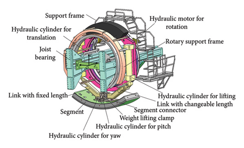
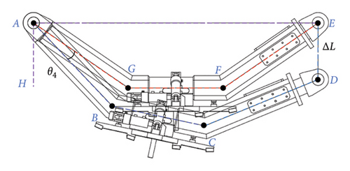
As seen in Figures 3 and 4, when the two piston rods had the same displacements relative to the hydraulic cylinders, the straight line that connected these two hinged points (line between A and E) was paralleled to the center line of the weight lifting clamp (line between G and F). In this condition, the link with a changeable length and the link with a constant length were of the same length, and the overall frame was shown as a trapezium AGFE. When the two piston rods had different displacements relative to the hydraulic cylinders, the straight line that connected these two hinged points (line between A and D) was unparalleled to the center line of the weight lifting clamp (line between B and C), which meant that the link with the changeable length had a different size as the link with the constant length, then the overall frame is shown as a pentagon ABCDE. Furthermore, if the displacement of the two lifting cylinders were different, the framework would change from trapezium AGFE to pentagon ABCDE, which was the first typical characteristics of the 6-DOFs segment assembly machine shown in this paper.
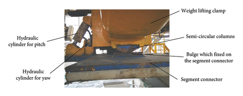
As shown in Figure 5, the weight lifting clamp was connected to the segment connector with a spherical hinge. There were two semicircular columns welded in the bottom of the two links, and the two semicircular columns were tangent to the two bulges which fixed on the segment connector. This special construction restricted one of the three rotation movement of the segment connector relative to the weight lifting clamp. Though there was a spherical hinge between the segment connector and the weight lifting clamp, there were only two degrees of freedom between them which was the second typical characteristics of the 6-DOFs segment assembly machine shown in this paper.
3. Kinematics Characteristics
In order to describe the relative motion of each joint, a coordinate system was established, which is shown in Figure 3 [15]. The base coordinate system O0X0Y0Z0 of the segment assembly machine was attached to the joist bearing which was regarded as a fixed trestle; Z0 pointed to the translational direction of the support frame which was driven by two identical hydraulic cylinders for translation; Y0 was opposite to the direction of gravity; and X0 could be obtained by the right-hand screw rule.
As shown in Figure 6, θ5 was used to describe the yaw angle of the segment connector relative to the coordinate axis which was fixed on the weight lifting clamp, parallel to Y0, and passed through the center point of the spherical hinge between the segment connector and the weight lifting clamp of the segment connector. θ6 was used to describe the pitch angle of the segment connector relative to the coordinate axis which was fixed on the weight lifting clamp, parallel to X0 and passed through the center point of the spherical hinge between the segment connector and the weight lifting clamp of the segment connector.
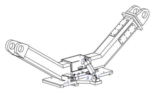
In theory, the yaw motion θ5 of the segment connector realized by the hydraulic cylinder for yaw (as shown in Figure 5) corresponded to the displacement of the hydraulic cylinder d5; in the same situation, the pitch motion θ6 of the segment connector realized by the hydraulic cylinder for pitch (as shown in Figure 5) corresponded to the displacement of the hydraulic cylinder for pitch d6. If the joint drive of θ5 and θ6 was motors or hydraulic motors, θ5 and θ6 would not interface with each other. However, the hydraulic cylinders were simple in structure and reliable in operation. When they were used to achieve the reciprocating movement, the deceleration device could be eliminated, and there was no transmission gap. In addition, considering the installation space limitation and the load capacity requirements, hydraulic cylinders were chosen as the joint drivers of the yaw motion θ5 and the pitch motion θ6.
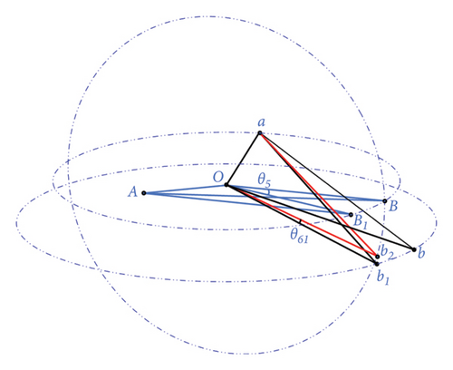
The relationships between yaw motion θ5, the pitch motion θ6, and displacements d5 and d6 of the corresponding hydraulic cylinders were not as simple as they were expected. There were coupling relationships between the displacements of the two cylinders and the two joints angular displacements (as shown in Figure 6).
As shown in Figure 6(a), Point “A” and Point “B” were the initial place of the hydraulic cylinders for yaw and Points “a” and “b” were the initial place of the hydraulic cylinders for pitch. “O” was the center point of the spherical hinge between the segment connector and the weight lifting clamp. As shown in Figure 6(b), when the hydraulic cylinder for the yaw shortened a certain distance, the plane OBb rotated to the plane OB1b1; at the same time, the elongation of the hydraulic cylinders for pitch should change from the length between a and b to the length between a and b1. In fact, the elongation of the hydraulic cylinders for pitch did not change at all. So, the plane OB1b1 required to rotate θ61 to the place where the length between a and b2 was the same as the length between a and b. The net result was that the length change of the hydraulic cylinders for yaw brought influences not only to the yaw rotation of the segment connector but also to the pitch rotation of the segment connector. For the same reason, the length change of the hydraulic cylinders for pitch brought influence not only to the pitch rotation of the segment connector but also to the yaw rotation of segment connector.
Furthermore, when the displacements of hydraulic cylinders of the segment connector were assigned, the explicit functions of the joint angles θ5 and θ6 could not be obtained because the coupling relationships between the length change of the two driving hydraulic cylinders of the segment connector and the corresponding joint angles θ5 and θ6. The coupling relationships between θ5 and θ6 and d5 and d6 were the third typical characteristics of the 6-DOFs segment assembly machine shown in this paper.
4. Motion Realization
For the relationships between the joint rotative angles and the displacement of the driving hydraulic cylinders were more complex and intricate than they were expected, the paper built the kinematics models by the simulation software. Firstly, SolidWorks model of the 6-DOFs segment assembly machine was imported to ADAMS mechanical dynamics simulation software, which was designed by Shandong Jiaotong University and Jinan Heavy Industries Group Co., Ltd. Then, using the cosimulation system of ADAMS2017 and MATLAB R2017a, the virtual simulation experiment was carried out, as shown in Figure 7. For this experiment was only to collect the kinematics parameters of the segment connector and the displacements of the hydraulic drivers, an open-loop control system was used here.
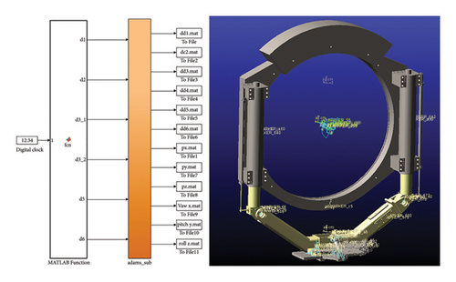
The virtual simulation experiment consisted the following steps: Firstly, importing the mechanical model to ADAMS; secondly, adding kinematic pairs to corresponding joints; thirdly, adding position driver to the corresponding kinematic pair, each joint trajectory should cover their whole movement range; fourthly, with the help of the cosimulation system, emitting joint movement signals which equal to the displacements of the hydraulic drivers and gathering kinematics parameters of the segment connector. To be sure, the simulation process was without gravity interference, and the communication interval between the MATLAB and ADAMS must be larger than the sample interval of the capital clock of MATLAB.
By aforementioned work, the relationships between the positions and postures of the segment connector and joints displacement of the segment assembling machine could be built. The smaller the sample time of the capital clock or the longer the simulation time, the more parameters of the positions and postures of the segment connector and joints displacement of the segment assembling machine could he gathered. Based on the data gathered from the virtual simulation experiment, there were multiple methods to obtain the numerical solutions of the invers kinematics, which meant if the position and posture of the segment connector were given, the joints displacement of the segment assembling machine could be obtained. In addition, the forward kinematics relationships also could be obtained with the same numerical computation methods, though the analytical solutions of the forward kinematics could be given out.
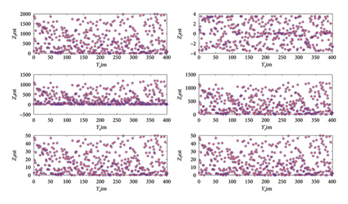
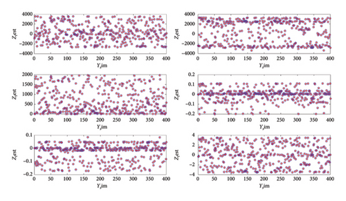
MATLAB function “newrbe,” which could design a radial basis network with zero error on the design vectors, was used to build the relationships between the position and posture of the segment connector and the joints displacement of the segment assembling machine in this paper. The sample time of the capital clock of MATLAB was set as 0.001, and the simulation time was set as 20 s, then 20,001 groups parameters could be obtain, which included six displacement parameters of the hydraulic drivers and six position and posture parameters of the segment connector. 80% of the 20,000 groups’ parameters were used to train the radial basis network, and 20% of the 20,000 groups’ parameters were used to test the radial basis network. The test results are shown in Figure 8. Set six position and posture parameters of the segment connector as input and six displacement parameters of the hydraulic drivers as output, and the inverse kinematics model could be obtained. As shown in Figure 8(a), the determination coefficient R is 1.000000; the mean square error (MSE) is 0.000000; the root mean square error (RMSE) is 0.000054. Set six displacement parameters of the hydraulic drivers as input and six position and posture parameters of the segment connector as output, and the forward kinematics model could be obtained. As shown in Figure 8(b), the determination coefficient R is 1.000000; the MSE is 0.000000; the RMSE is 0.000498.
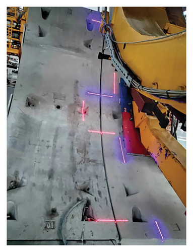
The kinematics modelling method proposed in this paper was used in the segment assembly experiment successfully. Based on the feedback information provided by the laser sensor, the encoders and the displacement sensors added on the hydraulic drivers, combined with the kinematics modelling provided in this paper, and the segment assembly experiment could carry out smoothly, as shown in Figure 9.
5. Conclusions
In summary, this paper introduced the 6-DOFs segment assembly machine designed by Shandong Jiaotong University and Jinan Heavy Industries Group Co., Ltd. Secondly, the paper analyzed the kinematics mechanism and pointed out the mechanism characteristics of the segment assembly machine which was driven by six hydraulic cylinders and two hydraulic motors. Thirdly, the paper gave out the reason why there was no analytical solution for this mechanism. Fourthly, the paper provided a simple kinematics modelling method. The effectiveness and feasibility of the modelling method proposed in this paper were verified by the segment assembly experiment.
Conflicts of Interest
The authors declare no conflicts of interest.
Funding
This research was funded by the Key R&D Program of Shandong Province, China (Grant number 2019JZZY010428).
Open Research
Data Availability Statement
The data used to support this research are included within this paper.


