Improving the Performance Characteristics of Three-Phase Asynchronous Induction Motor Drive Using Hybrid Systems Control Method Based on Direct Torque Control
Abstract
In this study, a hybrid control method based on direct torque control (DTC) was introduced to enhance the performance features of the three-phase asynchronous induction motor drive. Model-based predictive control methods are among the types of control methods used for hybrid systems. In the suggested method, the concepts of flux and torque vector orientation were utilized to decrease the impacts of flux and torque ripples in a multiobjective cost function. Subsequently, the optimal voltage vector was chosen according to the minimization of the intended objective function by applying the predictive control concepts. In this technique, the selection of the optimal vector is more guaranteed compared to the DTC method in accordance with the table since the objective function is assessed in every control cycle and the optimal voltage vector is chosen accordingly. In addition, the implementation of the suggested control method is easily possible. Based on the results of the simulation, the presented control method outperformed the classical torque direct control and predictive torque control (PTC) method in the flux and torque fluctuation results.
1. Introduction
Induction motors, among the different types of electric motors, are mostly utilized in industry and have the highest contribution to electrical energy consumption in a wide range of industries. High-quality and novel types of electric machines have been presented in recent years. Nonetheless, induction motors, due to their highly resistant structure, longevity, and inexpensive production and maintenance costs, have maintained their superiority over different types of modern electric machines [1].
Controlling electric motors has been one of the difficulties of alternating current electric machines since the invention of these machines. It should be noted that controlling different output features of induction machines is not a simple process for various reasons. The motor load is not constant in all industrial processes. In addition, the preliminary electrical parameters at the initiation of the motor, including stator and rotor resistances and machine inductance, typically change during the operation. These alterations adversely affect the control performance of the induction motor drive. Considering the role of the electric drive control algorithm, various studies have recently been performed in this regard [2–4]. The electric drive system is hybrid and includes continuous and discrete dynamics since the electric motor has steady behavior and the drive-related inverter should control this machine in a discontinuous process to hit the intended goals. Hence, the expansion of hybrid control algorithms has received extensive attention in the electric motor and inverter set, including a mixture of continuous and discrete dynamics [5]. Model-based predictive control is one of the techniques that is based on hybrid systems. In this technique, by taking into account the inverter’s discrete nature and looking for the optimal mode among the available switching modes of that inverter, an online optimization process is expanded to solve the problem associated with motor control. The control nature, with a finite number of commands per control cycle, facilitates the application of nonlinear modes and some limitations [6].
It is noteworthy that to enhance the control performance of systems that encompass electric drives, a developed drive control system should have proper performance features, including quick dynamic response, exact command tracking control with low ripples in the output torque, and the least possible dependence on variations in electric motor parameters. The mentioned methods are normally classified into two groups. Current vector orientation is based on vector control (FOC) in the first group, and the direct generation of the voltage vector is dependent on direct torque control (DTC) in the second group [7, 8].
In FOC-based techniques, the torque response dynamics are extremely slower compared to DTC-based ones. However, the steady-state response in current vector orientation methods has extremely fewer torque ripples in comparison to DTC-based methods [9]. Given the advantages and disadvantages of both of these methods, it seems highly influential and favorable to introduce a control algorithm that can possess the advantages of both methods while simultaneously avoiding their disadvantages. In this respect, predictive torque control (PTC) is an influential approach. In one study, the mentioned technique was employed to control the induction motor’s flux and torque [10]. In another study [11], DTC principles were utilized in the PTC method. These control strategies require no complex transformations and computations for vector orientation (e.g., the Park transformation). Furthermore, control of flow and adjustment of proportional–integral controllers can be neglected in this type of control. A high frequency of sampling is one of the requirements of these types of control methods, and the implementation of these algorithms has been facilitated owing to the increasing advancement in today’s high-powered and modern processors, such as the field-programmable gate array (FPGA) and digital signal processing (DSP).
On the other hand, topologies associated with multilevel inverters can be utilized to decrease different types of ripples in electric drives. These multilevel inverter topologies are not typically employed in predictive control methods owing to high-volume computations. Nonetheless, optimizations with various and conflicting objectives, higher prediction horizons, operation without sensors, and methods of weight coefficient adjustments in the cost function of the control technique noticeably increase the volume of computations [12]. The implemented control technique should be simplified through some strategies when it increases the calculation load [13].
Methods that are based on the selection of the direct torque vector also have some drawbacks that restrict their application in some electric drives. For instance, in one study [14], a space vector modulation (SVM) switching method was developed to enhance DTC performance. The suggested control method was based on SVM discretization. The calculation time was increased in this method by duplicating the sampling cycle in comparison to conventional DTC. Voltage vector selection by the table is another drawback of these methods. Selecting voltage vectors through the flux and torque table in DTC does not always result in optimal selection. Particularly, the space vector’s angle at the borders of the six regions probably results in choosing the wrong vector in the process of motor control, thus increasing the number of ripples in the electric motor’s torque output. Duty cycle control is among the methods to decrease torque ripples in electric drives based on the voltage vector’s direct selection. Methods that are based on duty cycle control have been employed to decrease flux and torque ripples in the electric motor control [15]. Such methods are utilized to enhance the engine’s steady-state response and normally have no quick, dynamic response. Moreover, they have a high computational load [16, 17].
In the present study, standard DTC has been considered and discussed as the basis of the intended control concept. Next, it has been attempted to decrease the impacts of flux and torque ripples in a multiobjective cost function by applying flux and torque vector orientation concepts. Subsequently, the predictive control concept is used to select the optimal voltage vector based on the minimization of the intended objective function. Considering the hybrid concept of the intended control method, it is presumed that the system’s dynamic response is comparable to the transient response in conventional DTC while enhancing the electric motor’s steady-state response. In such a method, selecting the optimal vector is further guaranteed compared to the table-based DTC method since the objective function is assessed in every control cycle, and the optimal voltage vector is chosen accordingly. Moreover, the implementation of the presented control method is simply possible. Overall, the proposed control method can outperform classical DTC.
In the introduced method, the voltage vector applied to the inverters has been linked to dynamic machine equations by machine equations while avoiding decision-making based on fixed tables. The eminent innovation of the suggested method is the relation of the voltage vector to the machine’s output torque; nonetheless, this issue has not received much attention in the past. One advantage of the suggested method is that it has less dependence on motor parameters compared to methods that are based on vector current orientation. Hence, the introduced method has an extremely higher dynamic response speed compared to vector methods, while it has fewer torque ripples in comparison to table-based DTC. The remaining sections of the article are organized as follows.
Section 2 provides the squirrel-cage induction motor’s equations and modeling, followed by a description of the general principles of DTC. The suggested hybrid control method is provided with a thorough description of the cost function in Section 3. The simulation results of proposed control method, DTC and PTC methods are presented in Section 4. Section 5 discusses the results of the simulation and then compares them with those of DTC and PTC methods. Eventually, the conclusion is presented in Section 6.
2. Induction Motor Equations and DTC
2.1. Induction Motor Modeling and Principles
2.2. DTC
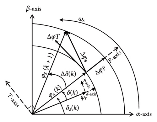
Equation (3) demonstrates that the dynamics and its torque ripple directly depend on variations in the δ angle. Thus, a sudden change in this angle can lead to quick control of the torque.
| Δφ | ΔT | Sector number | |||||
|---|---|---|---|---|---|---|---|
| 1 | 2 | 3 | 4 | 5 | 6 | ||
| Increase | Increase | V2 | V3 | V4 | V5 | V6 | V1 |
| Constant | V7 | V0 | V7 | V0 | V7 | V0 | |
| Decrease | V6 | V1 | V2 | V3 | V4 | V5 | |
| Decrease | Increase | V3 | V4 | V5 | V6 | V1 | V2 |
| Constant | V0 | V7 | V0 | V7 | V0 | V7 | |
| Decrease | V5 | V6 | V1 | V2 | V3 | V4 | |
These are the most ordinary and simplest relationships in electric drives that are employed for most DTC-based methods.
3. The Suggested Hybrid Control Method
As previously mentioned, the flux and electromagnetic torque are controlled by applying the optimal voltage vector to every control cycle. Considering that DTC utilizes a constant and particular switching table to apply the voltage vector, it cannot be guaranteed whether the applied voltage vector can perfectly function in all working conditions of the machine and all flux angles and areas [19]. The suggested hybrid control method looks for the optimal voltage vector by assessing a cost function on a decision platform with limited choices. According to the conditions taken into account in the cost function, it can be guaranteed that the chosen voltage vector will yield the best outcome.
As mentioned earlier, following computing flux variation components, the optimal voltage vector should be chosen based on control objectives. The optimal voltage vector will be selected by searching among various voltage vectors after assessing a suitable cost function.
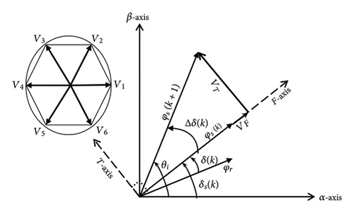
In (18), is the ith voltage vector applied to the stator, which transforms into two components along the F/T axes.
Eventually, the optimal voltage vector is chosen through minimizing the objective function of equation (19) by investigating the possible voltage vectors that are applied to the two-level voltage inverter.
The control diagram block associated with the suggested method is displayed in Figure 3. In this method, the magnitude of the flux variation component in a control loop is achieved based on the estimation results in DTC. Subsequently, the objective function is minimized by looking for the voltage vector.
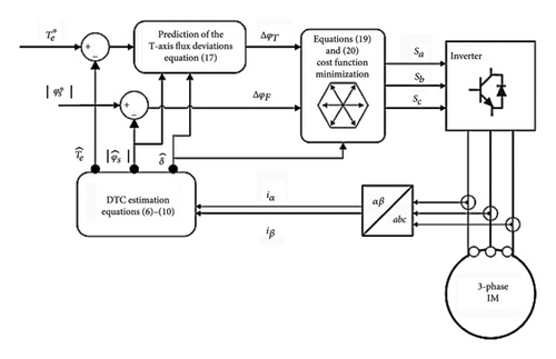
In the suggested method (as shown in the block diagram in Figure 3), there is no concentration on speed control, and it is mainly aimed to control the machine torque. Therefore, in the block diagram of the presented method, it has been attempted to concentrate on and present more details about the torque control method. A conventional speed PI controller has been utilized to present results for speed stabilization and examine the steady-state response.
The different types of predictive control methods, which have so far been introduced regarding electric drives in order to control the movement of electric motors, employ electric currents and the orientation of the currents of the dq axes of the machine based on predicting the behavior of the machine. In previously introduced methods, electric currents were typically oriented based on vector control methods via predicting the behavior of the machine’s next moments based on the electric machine’s descriptive equations. The complexity of computations, the loss of time, and the slowing down of the motor control process are important disadvantages of methods based on electric current orientation. On the other hand, methods that are based on the direct application of the voltage vector to the machine (e.g., DTC) have no important relationship with machine equations. Such methods normally apply the voltage vector command to the inverter from fixed tables. These tables are predetermined and have drawbacks, thus increasing the ripple in the torque output of the engine.
In the suggested method, the voltage applied to the inverters has been associated with the dynamic equations of the machine by vector machine equations. Moreover, no decision has been made based on fixed tables. The distinguished innovation is the introduced method about the relationship of the voltage vector to the torque output of the machine, which has received less attention in the past. According to equations (17)–(20) and some approximations, equations were obtained that can be employed for the implementation of the predictive control method based on the machine voltage. While the proposed method requires motor inductances parameters, it avoids dependency on rotor and stator resistances, simplifying implementation compared to FOC. Therefore, the advantages of the suggested method include less dependence on motor parameters compared to methods based on vector current orientation. Accordingly, the proposed method has an extremely higher dynamic response speed in comparison to vector methods while having fewer torque ripples than the table-based DTC method.
4. Results
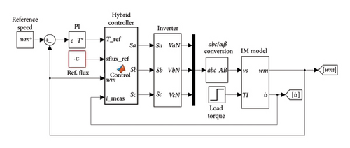
In this section, the results of the simulation by MATLAB/Simulink software are provided to validate the suggested method. Figure 4 illustrates the simulation conducted on the MATLAB/Simulink platform. The results have been assessed in steady-state and dynamic modes. All the results of the suggested method were compared with those of DTC and PTC. All regulatory parameters, such as the sampling time, were considered to be the same in order to fairly evaluate and compare the two methods. In this study, the sampling time was considered to be 40 microseconds. Different specifications associated with the motor and other induction motor drive parameters are listed in Table 2.
| Parameter | Value |
|---|---|
| Phase number | 3 |
| Number of poles | 2 |
| Rated frequency | 50 Hz |
| Rated power | 8.5 kw |
| Stator rated current | 13.5 A |
| Stator rated voltage | 400 V |
| Rated torque | 20 N.m |
| Rated speed | 2820 rpm |
| Stator resistance | 1.2 Ω |
| Rotor resistance | 1 Ω |
| Stator inductance | 175 mH |
| Rotor inductance | 175 mH |
| Mutual inductance | 170 mH |
To achieve the results, a normal PI controller was employed to control the speed at a fixed value of 150 rad/sec. In this simulation, a normal-speed PI controller was applied to control the motor speed. In this study, speed control received no attention, and it was merely utilized to fix the speed in order to examine the suggested method’s steady-state response.
The output of the mentioned controller can determine the reference torque applied to the machine. The flux reference value for all methods was considered to be 0.7 wb.
4.1. Proposed Method
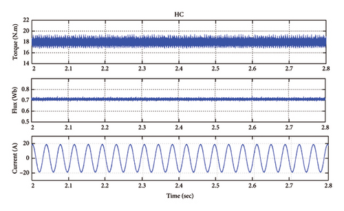
The results of the simulation are provided for the proposed method under the mentioned and similar regulatory conditions. Figure 5 displays the steady-state results of the measured current associated with the stator, the stator flux, and the output torque by the machine. Based on the proposed method results, the stator flux and torque fluctuations are 1.15% and 2.63%, respectively.
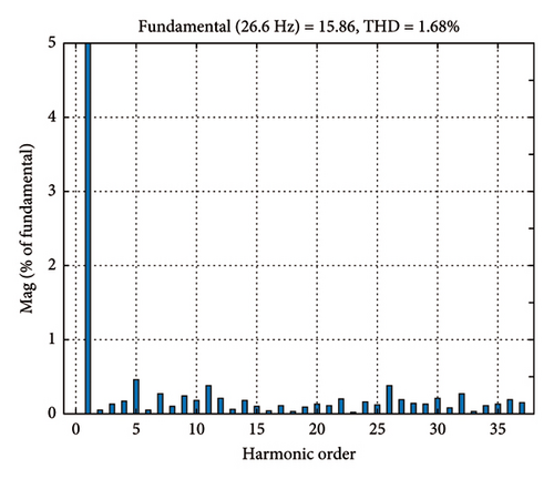
The stator current’s harmonic spectrum for one of the stator phases in a steady state is illustrated in Figure 6. Based on this spectrum, the total harmonic distortion (THD) of the stator current is 1.68% for the proposed method.
In order to investigate the transient behavior of the proposed method, a step torque command from 1 to 18 N.m has been applied. Figure 7 shows torque response of the control method. The torque step response of both control algorithms is fast and the rise time of torque response is 0.45 ms.
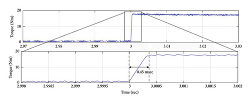
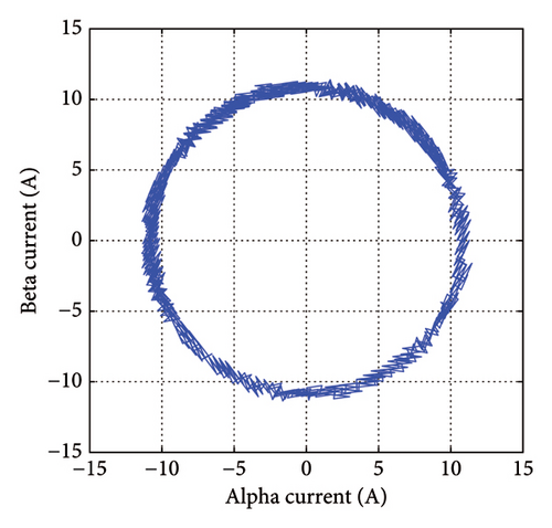
Figure 8 depicts the simulation results related to stator current paths in α-β coordinates using the suggested method. As shown, the introduced method has a satisfactory performance in terms of the current ripple in the steady-state response.
4.2. DTC Method
The simulation results of the DTC method are presented in the same regulatory conditions with the proposed method. Figure 9 displays the steady-state results of the stator measured current, the stator flux, and the output torque by the machine. Based on the DTC results, the stator flux and torque fluctuations are 1.25% and 3.385%, respectively.
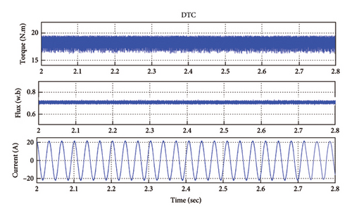
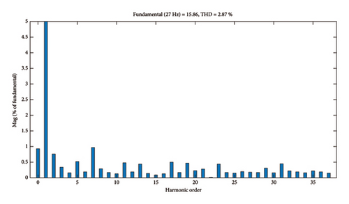
The stator current’s harmonic spectrum for one of the stator phases in a steady state is illustrated in Figure 10. For the DTC method, based on this spectrum, the THD of the stator current is 2.87% for the proposed method.
4.3. PTC Method
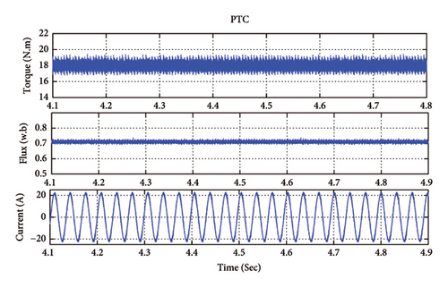
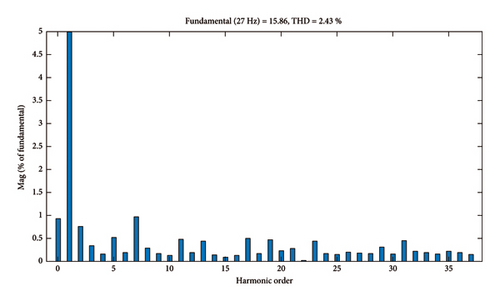
The simulation results of steady-state behaviors of PTC method are presented in Figure 11. The stator flux and torque reference values are 0.7 Wb and 18 N.m, respectively. The results are presented as follows: torque, stator flux and measured motor current. A comparison of the steady-state performances in terms of torque ripple, stator flux ripple, and THD of the stator current is presented in Table 3. The ripples are calculated from equations (21) and (22). The THD spectrum of the stator current is shown in Figure 12 and based on these results the THD is to be calculated 2.43%.
| Parameter | Proposed method | DTC | PTC |
|---|---|---|---|
| Flux ripple | 1.15% | 1.25% | 1.23% |
| Torque ripple | 2.63% | 3.385% | 2.66% |
| Stator current THD | 1.68% | 2.87% | 2.43% |
| Frequency (kHz) | 6.355 | 6.468 | 6.386 |
5. Compressions and Discussions
The results of the simulation are provided for the proposed, DTC and PTC methods under similar regulatory conditions in the previous section. In order to evaluate and compare the proposed method with the DTC and PTC methods Table 3 is presented. The results revealed that the stator current’s overall distortion was 1.68%, 2.87%, and 2.63% in the proposed method, DTC and PTC methods, respectively. Therefore, the presented method is closer to the pure sinusoidal current waveform.
All three presented control methods are differed in terms of the nature of the switching-frequency methods. Thus, these methods, unlike vector control and other pulse width modulation-based methods, have no fixed switching frequency. Nonetheless, even for these methods, an average value can be provided for the switching frequency in the steady state. The average switching frequency in the proposed DTC and PTC methods was 6.355, 6.468, and 6.386 kHz, respectively.
As shown in Section 3 and the presented results, the introduced method has a satisfactory performance in terms of the current ripple in the steady-state response. Table 3 compares the three methods. The values of the flux and torque ripples, as well as the total distortion of the stator electric current, were compared between all three methods. The results confirmed that the flux and torque ripples and the overall distortion of the stator current in the suggested method were less than those in DTC and PTC.
6. Conclusion
A DTC-based hybrid control method was provided in this study, which could improve the performance features of the three-phase asynchronous induction motor drive. In this method, the optimal voltage vector was selected by using the predictive control concept and relying on cost function optimization. In the proposed method, selecting the optimal vector could be more guaranteed compared to table-based methods like DTC since the objective function was assessed in every control cycle, and the optimal voltage vector was selected accordingly. The results of the simulation demonstrated that, compared to classical DTC and PTC, the suggested method had a fast dynamic response and fewer flux and torque ripples in the steady-state conditions. In addition, its implementation is easily possible.
Conflicts of Interest
The authors declare no conflicts of interest.
Funding
This research was performed in the Islamic Azad University in Iran.
Open Research
Data Availability Statement
The data that support the findings of this study are available on request from the corresponding author. The data are not publicly available due to privacy or ethical restrictions.


