A Novel TLBO-Based Antenna Array Imperfection Calibration for Effective DOA Estimation in mmWave mMIMO Systems
Abstract
Antenna Array imperfection calibration is an important concern in direction-of-arrival (DOA) estimation in 5 G millimeter Wave (mmWave) massive Multiple Input Multiple Output (mMIMO) systems. As the number of elements in mMIMO systems increases, array imperfections tend to increase, degrading the DOA estimation performance. Existing calibration techniques use the local optimum solution as the gain/phase, and the location error is high. The present work proposes an inter-disciplinary learning teaching-learning-based optimization (IDL-TLBO) to estimate the DOA. This algorithm exploits the joint sparse properties of the DOA vector and array perturbation matrix. Benefitting from inter-disciplinary learning and sparse properties, the global search capability of the proposed method enhances the accuracy of DOA estimation. The efficacy of the proposed IDL-TLBO was validated using various simulation scenarios. Simulation results reveal that the proposed method achieves a better performance-complexity trade-off than conventional methods for DOA estimation.
1. Introduction
Enhanced Mobile Broadband (eMBB) is one of the 5G use cases that aims to provide higher bandwidth, higher throughput, and high data rates. The mmWave and mMIMO are key techniques to enable eMBB services. The massive MIMO systems employ beamforming techniques to focus the radio signal on a specified user and provide greater user capacity in high-traffic locations. To improve signal reception and reduce interference, the DOA of the incident signal was estimated to evaluate beamforming vectors to steer the beam to the intended user. DOA is a subset of effectual beamforming techniques [1], and these vectors subsequently track the appropriate signal sent from the User Equipment (UE). Accurate DOA estimation is essential to maximize the power of the received signal and reduce the interference signal from nearby sources, which subsequently increases the capacity of mMIMO systems [2].
In practical scenarios, the array manifold is prone to random errors and noise, and it increases as the mMIMO size increases, which successively degrades the DOA estimation performance. Owing to the imperfections in the calibrated array, array perturbations such as gain/phase uncertainties and position perturbations exist. Different techniques have been proposed using a minimal number of antenna elements in MIMO systems to annihilate gain/phase perturbations [3–6]. To obtain a certain array geometry, the inter-element spacing (d) is required to place the elements in the array. Owing to the imperfect placement of the array elements, it introduces a few unavoidable position errors, perturbing the ideal array manifold. Hence, unknown location errors were estimated to compensate for perturbations, and a DOA estimation was performed [7–9]. In [10] a PARAFAC decomposition model with imperfections in an antenna array was used to estimate the DOA. Subsequently, the 2D-DOA estimation with imperfections is proposed by utilizing calibration techniques [11], and a framework for the 2D-DOA estimation within a specified grid is presented with the assumption of gain/phase imperfections in a uniform rectangular array [12]. In recent studies [13, 14], many sparse reconstructions were performed to estimate imperfections based on a discrete dictionary. The -norm [15] was employed to enforce the sparse solution of the perturbation matrix. A sparse technique is employed to estimate the DOA with respect to gain and phase errors in the array [16]. The sparse techniques in [17, 18] have proposed 2D DOA estimation with V and L shaped arrays. The antenna array imperfections considered in the proposed study are gain/phase errors and antenna element location errors in mMIMO systems. Hence, these perturbations must be minimized to achieve a high-resolution DOA estimation.
The sparsity of DOAs is typically explored by creating a dictionary matrix comprising the possible steering vectors in the spatial domain. The -norm based methods in DOA estimation techniques offer superior performance compared to traditional subspace methods [19] despite having limited snapshots and a low signal-to-noise ratio (SNR). The major limitation of the existing array calibration technique using the MUSIC-based objective function is that it requires the approximate DOA to be known and then estimates the banded array perturbation matrix [20]. Hence, the joint estimation of the DOA and perturbation matrix becomes challenging with array imperfections using a subspace-based algorithm.
In the sparse-based DOA estimation [21], the norm-based objective function is solved sequentially using convex optimization, which requires a greater number of iterations until the adjunct DOA estimation is less than the threshold. The teaching-learning-based optimization (TLBO) is a meta-heuristic algorithm [22] and it has been applied to many practical applications in diverse fields. As the array imperfections tend to grow in mMIMO systems, the TLBO converges easily at local optimum solution. To alleviate the limitations of joint estimation of direction finding and perturbation matrix, a novel method combining inter-disciplinary learning with TLBO (IDL-TLBO) is proposed, which optimizes norm-based objective function to estimate the DOA and perturbation matrix. Henceforth, the proposed IDL-TLBO improves the global search ability with the help of interdisciplinary learning incorporated in TLBO, which outperforms conventional subspace-based methods with TLBO and PSO [23]. IDL-TLBO improves the accuracy of the DOA estimation by utilizing two different disciplines of interdisciplinary learners in the search space. In the presence of array imperfections, the proposed work jointly estimates the array perturbation matrix and DOA of the UE. The calibration of the array is performed with the help of the estimated array perturbation matrix, and further the channel state information, target parameter estimation can be characterized to estimate the doppler shift, DOA, multipath delay using an iterative estimation method [24] in mMIMO systems.
In the proposed work, a unified framework for DOA estimation using the IDL-TLBO algorithm is proposed in the presence of perturbations such as array element position errors and gain/phase uncertainty. The significant part of this study is to utilize the sparse property of the signal. The DOA vector remains sparse in accordance with the spatial dictionary, and array perturbations such as gain/phase uncertainty, array element position error can also be represented by a sparse matrix. The rest of this paper is arranged as follows. Section 2 presents the modelling of the DOA estimation problem. In Section 3, the framework for antenna array perturbations is presented. In Section 4 and 5, the basic TLBO and the proposed IDL-TLBO techniques are described. Section 6 illustrates the DOA estimation with array perturbations using the proposed IDL-TLBO technique. The simulation results are presented in Section 7, and Section 8 represents the conclusion of the study.
2. The Problem Modelling
2.1. System Model
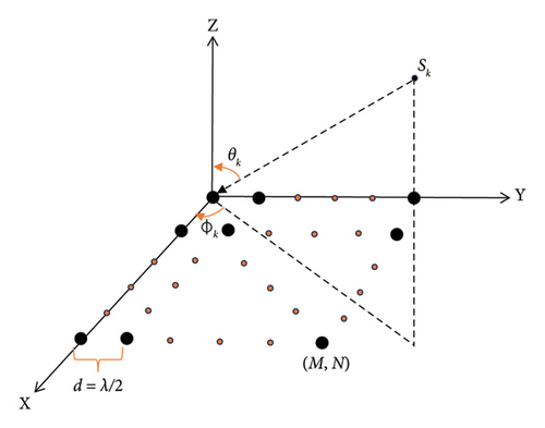
The DOA estimation technique estimates the sparse DOA s from the measured signal y.
2.2. Channel Model
Accurate channel modelling is essential for mmWave massive MIMO systems that use narrow beam antenna arrays to steer at the signal source. An open-source channel simulator NYUSIM was developed by scholars at New York University (NYU), which relies on real-world propagation at mmWave frequencies ranging from 28 to 73 GHz in several outdoor environments, such as rural microcell (RMa), urban macrocell (Uma) and urban microcell (UMi) environments [26].
Channel parameters contain basic input parameters for the channel, which comprises of carrier frequency, RF bandwidth, scenario, environment, upper bound of the T-R separation distance(m), lower bound of T-R separation distance(m), TX power(dBm), number of receive locations, temperature, barometric pressure, humidity, polarization, foliage loss, rain rate, distance within foliage, and attenuation of foliage. The panel incorporates input parameters appropriate to the transmit and receive arrays such as the number of antenna elements, array type, transmit and receive inter-element Spacing, Number of transmit and receive antenna elements per row, transmit and receive antenna azimuth HPBW, transmit and receive antenna elevation HPBW.
| Channel parameters | Antenna parameters | ||
|---|---|---|---|
| Frequency | 28 GHz | No of Tx antenna elements | 8 |
| RF bandwidth | 800 MHz | No of Rx antenna elements | 256 |
| Scenario | Urban microcell (UMi) | No of Rx antenna per row | 16 |
| Environment | LOS | RX antenna spacing | 0.5 |
3. Antenna-Array Perturbations
3.1. Gain/Phase Uncertainties
3.2. Position Perturbation
3.3. Combined Perturbations
4. TLBO
The main idea of TLBO emanates from the influence of a teacher on the output of learners in a class and the interaction among the learners [22]. This optimization technique comprises of teacher phase and learner phase.
4.1. Teacher Phase
4.2. Learner Phase
5. The Proposed IDL-TLBO
IDL-TLBO is mainly based on IDL, it enables learners from multiple disciplines to solve complex problems from their discipline perspectives and through collaborative learning. IDL-TLBO also consists of teaching and learning phase similar to the basic TLBO.
5.1. Teacher Phase
5.2. Learner Phase
The inertia weight ω2 accelerates the difference between the teacher and learner to improve the learner’s mark and convergence speed. If there are two unknowns s and B, two discipline learners are initialised. The first discipline of learners works to estimate the optimized solution for s by using the initialised/estimated solution of B and the other discipline works to estimate the optimized solution for B by using the initialised/estimated solution of s. In each iteration, the optimized solution of each discipline is shared with the other discipline and this represents the collaboration in interdisciplinary learning.
6. DOA Estimation Using Proposed IDL-TLBO
In this section, we propose an IDL-TLBO technique to estimate DOA vector from the received signal as in (20). As there are two unknowns (design variables) namely DOA vector (s) and array perturbation matrix (B), the proposed optimization approach utilizes two disciplines to estimate the DOA and perturbation parameter. The incorporation of interdisciplinary learning in TLBO enhances the global searchability and accuracy of DOA estimation. The block diagram of DOA estimation using proposed IDL-TLBO is shown in Figure 6.
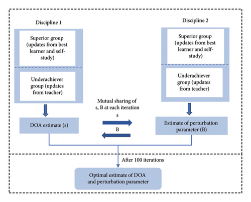
The two design variables namely array perturbation matrix (B) and DOA vector (s) must be estimated, in accordance with the objective function (20). Figure 6 infers that the IDL-TLBO is iterated with the initialized B within the search space to estimate the sparse DOA vector (s) by discipline 1 learners. Simultaneously, the perturbation matrix B is estimated with the initialized DOA vector within the search space by the discipline 2 learners. Then the optimized variables determined by each discipline are shared with another discipline to optimize the results of the array perturbation matrix (B) and the sparse DOA vector (s) in further iterations. The main hyperparameters of the algorithm are the number of learners (N) and the maximum number of iterations (T). The number of learners is initialized according to the number of elements in the antenna array and the maximum number of iterations is chosen as 100 for each discipline to balance the computational feasibility and solution accuracy. The search space of sparse DOA vector and array perturbation matrix lies between 0 and 1. More iterations are chosen to balance the exploration and exploitation to obtain an optimized solution and to avoid the risk of getting trapped in local optima. The two disciplines work in parallel to estimate the perturbation matrix, DOA vector as shown in Figure 6. The pseudocode of the IDL-TLBO algorithm is given in Table 2.
| 1 | Objective function of first discipline f(s), (i = 1, 2 , …, N) with ‘B’ being initialized/estimated using (20) |
| 2 | Objective function of second discipline f(B), (i = 1, 2 , …, N) with ‘s’ being initialized/estimated using (20) |
| 3 | Initialize algorithm parameters |
| 4 | Generate initial population |
| 5 | Evaluate the fitness of population |
| 6 | /Teaching phase/ |
| 7 | Update the mean value and divide the learners into two groups for each discipline |
| 8 | For each learner in population of each discipline do |
| 9 | If a learner is superior then, |
| 10 | Update new solution by using equation (23) |
| 11 | Else |
| 12 | Update new solution by using equation (24) |
| 13 | End If |
| 14 | Evaluate and update better solutions. |
| 15 | End For |
| 16 | /Learning phase/ |
| 17 | Learners are partitioned into two groups for each discipline |
| 18 | For each learner in superior group do, |
| 19 | Select a neighbour learner randomly |
| 20 | Update new solution by using equation (27) |
| 21 | End For |
| 22 | For each learner in underachiever group do, |
| 23 | Update new solution by using equation (28) |
| 24 | End for |
| 25 | Evaluate and update the best solution of s, B from two disciplines. |
| 26 | The updated solution of each discipline is mutually shared with the other discipline |
| 27 | Iter = iter+1. |
| 28 | Output the best solution found |
6.1. Computational Complexity Analysis
The IDL-TLBO algorithm comprises of initialization, cost function evaluation, and updating the position [32] of the variables from two disciplines. Initialization with the size of the population N is performed with [33]. Fitness evaluation is carried out in two disciplines with complexity of . The complexity of updating the position is indicated by , where T is the maximum iteration and D is the dimension size of the problem [34]. Henceforth, the computational complexity of the proposed IDL-TLBO is , as two disciplines are involved in IDL-TLBO.
7. Results and Discussion
7.1. Simulation Conditions
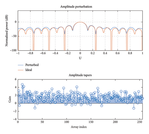
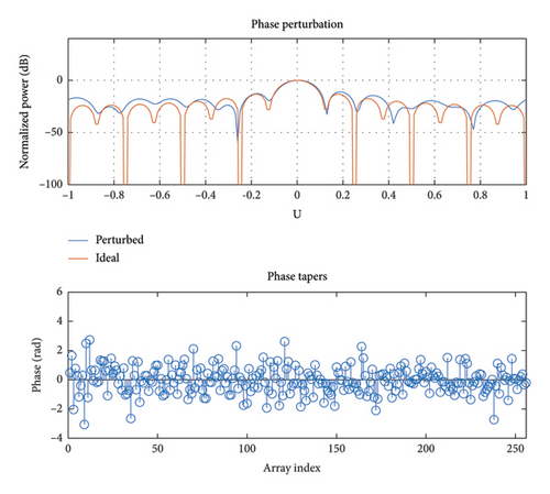
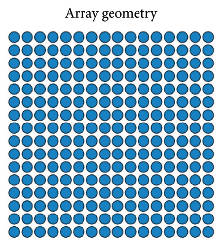
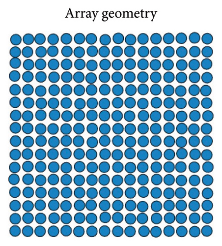
The performance of the proposed method is validated using the simulation results. We consider a gNB with a uniform rectangular array of size 16 × 16 with 256 elements and an inter-element distance of half the wavelength (λ/2) to collect the signals from the user. The channel coefficients were generated with NYUSIMv1.6 for accurate channel modelling and simulations for mmWave systems were used with an electrically steerable and narrow beam antenna array. The simulation results were executed using MATLAB R2022 to estimate the perturbation matrix of array and the DOA. The simulation parameters used to estimate the DOA are listed in Table 3.
| Simulation parameters | Values |
|---|---|
| Number of transmit antenna—Nt | 8 |
| Number of elements in receive array—M × N | 256 |
| Antenna array | URA |
| Interelement spacing—d | λ⁄2 |
| Number of user—K | 1 |
| Channel model | mmWave mMIMO statistical spatial channel model |
| Channel scenario | Umi |
| SD of position perturbation σmaxper | 0.5 |
| SD of inconsistent gain σmaxgain | 0.5 |
| SD of inconsistent phase σmax phase | 0.5 |
7.2. Simulation Results
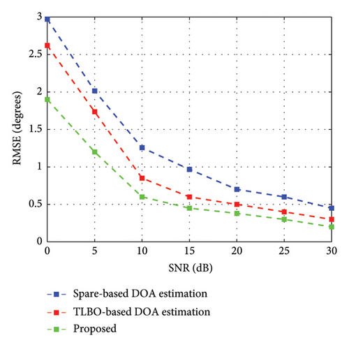
First, the proposed method is compared with sparse DOA estimation [21] and TLBO [23] as benchmarks for estimation accuracy by varying the SNR from 0 to 30 dB with a single snapshot accompanied by gain/phase inconsistencies and position perturbation. The results in Figure 7 show that the proposed technique has the lowest estimation error compared to sparse estimation and TLBO estimation. It also implies that the proposed technique has lowest RMSE at the low-SNR regime owing to enhanced learning in IDL-TLBO.
The traditional subspace-based method such as MUSIC performs well at high SNR region, as it requires a greater number of snapshots to estimate precise DOA and its performance depreciates, as the error grows larger in mMIMO systems. The sparse-based techniques and subspace-based MUSIC [35] estimation is implemented in mMIMO systems for comparison purposes. The performance of the existing work with the proposed work at SNR of 10 dB with single snapshot are tabulated in Table 4. It is observed that the estimated DOA using proposed work are closer to actual ones than the sparse-based and subspace-based techniques.
| DOA estimation techniques | Actual DOA (deg) | Estimated DOA (deg) | Estimation error (deg) | |||
|---|---|---|---|---|---|---|
| Azimuth | Elevation | Azimuth | Elevation | Azimuth | Elevation | |
| TLBO-based DOA estimation [23] | 70 | 4 | 69.16 | 3.35 | 0.84 | 0.65 |
| Sparse-based DOA estimation [21] | 70 | 4 | 68.85 | 5.34 | 1.15 | 1.34 |
| Subspace-based MUSIC [35] | 70 | 4 | 72.06 | 2.63 | 2.06 | 1.37 |
| Proposed work | 70 | 4 | 69.27 | 4.56 | 0.73 | 0.56 |
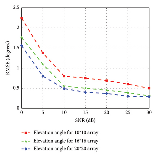
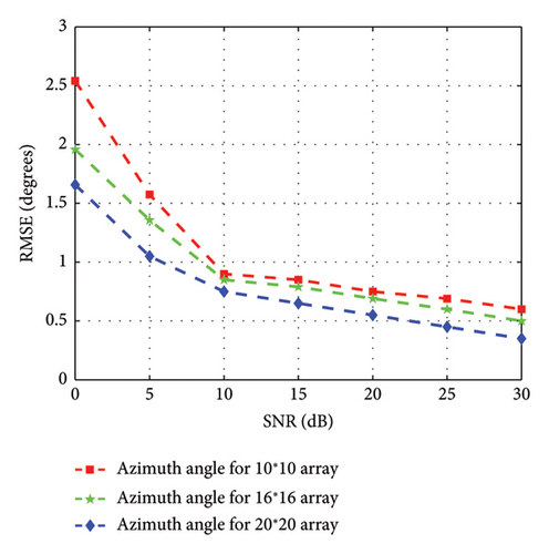
In the second scenario, the performance of the proposed technique is evaluated by varying the array sizes. The average RMSE for the elevation and azimuth angles versus the SNR are depicted in Figures 8 and 9, with the presence of gain/phase inconsistencies and position perturbation in this simulation. In accordance with Figures 8 and 9, it infers that the proposed technique provides better estimation accuracy for varying array sizes as the IDL-TLBO enhances the global search capability of learners. It is also observed that the proposed technique has lower RMSE with an increase in the size of the array.
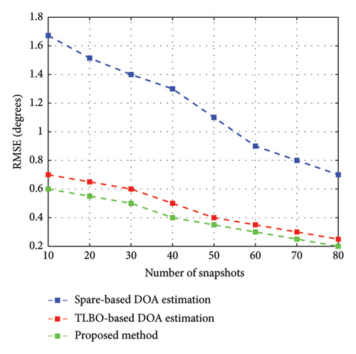
In simulation scenario 3, the performance of the DOA estimation was evaluated using different number of snapshots at a SNR of 10 dB. The number of snapshots varies from 10 to 80 at 10 intervals and this evaluation criteria infers that the DOA estimation performance improves as the number of snapshots increases in below Figure 10. In accordance with Figure 10, it infers that the proposed method has lowest estimation error than the benchmark algorithms because it is enhanced with global search capabilities.
The computational cost of the proposed work with existing studies is listed in Table 5. The complexity of the sparse-based DOA estimation [21] is given by , where K represents the number of column users in the dictionary steering matrix and n specifies the number of rows in the sparse DOA vector. The TLBO-based DOA estimation comprises of initialization process and position updation , where T represents the maximum iterations, N represents the population size and D represents the dimension size of problem. Thus, the total number of computations required for TLBO-based DOA estimation is given as [36]. The complexity of subspace-based DOA estimation [37] is , where M × N represents the number of array elements in URA. The computational complexity of the proposed IDL-TLBO is , as two disciplines are involved in IDL-TLBO. The number of computations involved in the proposed algorithm is more than the sparse-based TLBO in the estimation of DOA. The estimation of DOA accuracy increases in the low SNR region, as shown in the simulation results, and when compared with the traditional methods it brings about performance complexity trade-off for obtaining an accurate DOA estimate in the low SNR region.
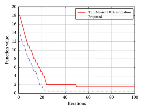
The convergence behaviour of the IDL-TLBO- and TLBO-based DOA estimation at SNR of 10 dB is depicted in Figure 11. It implies that the proposed optimization technique has enhanced convergence performance than the TLBO optimization technique. In our future work, we will further improve the DOA estimation performance with array imperfections for Hybrid Analog and Digital (HAD) architectures by using the IDL-TLBO. The sub-connected (SC) hybrid architectures could achieve the same performance as that of fully digital arrays. The proposed IDL-TLBO technique can be integrated with the switches-based (SE) hybrid architectures using switch optimization (SWO) [38] to estimate DOA and array perturbation matrix in mMIMO systems.
8. Conclusion
In this study, a novel optimization technique for estimation of 2D-DOA in 5G mmWave mMIMO systems in the presence of antenna position perturbation and inconsistent gain/phases have been proposed. The major motivation of the proposed method is inspired by the goal of applying sparse signal recovery methods. The joint estimation approach is formulated under the IDL-TLBO optimization framework by incorporating interdisciplinary learning strategies in TLBO. This mechanism improves the global search capability of DOA and increases the accuracy of the estimation in low SNR region. The simulation results reveal that the DOA estimation with the proposed IDL-TLBO outperforms the other existing DOA estimation schemes under different evaluation criteria.
Conflicts of Interest
The authors declare no conflicts of interest.
Funding
No funds were received.
Open Research
Data Availability Statement
The data supporting the findings of this research are available on request from the first author upon reasonable request.


