Four-Element MIMO Patch Antenna With High Gain, High Isolation, and Polarization Diversity Characteristics for 28-GHz Applications
Abstract
This article presents the design of a high-gain, highly isolated four-element multiple-input multiple-output (MIMO) antenna system operating at the millimeter-wave (mm-wave) 28 GHz frequency band. The radiating element of the MIMO antenna comprises a 1 × 2 array of crescent-shaped patch elements backed by a full ground plane, having overall dimensions of 33 × 33 mm2 (3.08λ × 3.08λ), where λ is the wavelength at 28 GHz. A 0.787-mm-thick low-loss dielectric substrate having a relative permittivity (εr) of 2.2 and a loss tangent (tanδ) of 0.009 is used for the antenna design. It is observed that the designed radiating element provides resonance at 28.18 GHz and has a 6.21% fractional bandwidth (FBW) and a peak realized gain of 10.5 dBi. The radiation and total efficiency of the radiator are noted to be >85% and ≥75%, respectively, in the operating bandwidth. For polarization diversity and high isolation characteristics, the MIMO elements are arranged in an orthogonal manner, which helps achieve an isolation of >22.5 dB for adjacent elements and >32.5 dB for diagonally placed elements in the entire band of interest. Furthermore, MIMO system parameters such as envelope correlation coefficient (ECC) <0.003, diversity gain (DG) >10 dB, total active reflection coefficient (TARC) < −10 dB, and channel capacity loss (CCL) <0.5 bps/Hz are observed, which fall within the operational limits. Based on the achieved outcomes, the proposed design is well suited for mm-wave 28 GHz communication devices.
1. Introduction
As the number of internet users grows rapidly and people use more wireless gadgets, there is a big demand for devices that offer faster data transfer and less delay [1]. The millimeter-wave (mm-wave) spectrum holds immense potential to transmit large amounts of data at incredibly high speeds, unlocking new levels of connectivity and innovation. From the mm-wave spectrum, the 28 GHz frequency band stands out because it does not absorb signals much and has a lot of unused space for new technology. These characteristics make the 28 GHz frequency band well suited for delivering high data rates and low latency required for advanced fifth-generation (5G) applications. To fulfill the abovementioned demands, the utilization of multiple-input multiple-output (MIMO) antenna technology is preferable, especially in higher frequency bands [2, 3]. In addition, the designed MIMO antenna system should provide high isolation among the radiating elements to achieve high channel capacity (CC). To accommodate the need, several MIMO antenna systems have been presented in the literature for mm-wave 5G connectivity.
In [4], a quad-port MIMO antenna system composed of a 1 × 2 array of patch antennas operating at 28 GHz was discussed. Through defected ground structure (DGS) and by placing antenna elements at different positions on the printed circuit board (PCB), isolation among radiating elements was enhanced. The performance of the MIMO antenna was further enhanced by placing an array of metasurface on top of it. This kind of configuration will produce high isolation but at the expense of bulky size. The same kind of configuration was utilized in [5], where the authors used a metasurface array placed at the backside of the designed MIMO antenna. The purpose of using the metasurface array was to improve the radiation characteristics as well as isolation performance. A similar kind of radiating structure and MIMO configuration as presented in [4] was designed by the authors in [6]. Interelement coupling was reduced by placing them orthogonally to each other, with the use of DGS, and by placing a linear array of metasurface structures between the radiating patches. The authors in [7] designed an asymmetric MIMO antenna configuration to achieve high isolation. Although the presented MIMO design offers high isolation, its use will be limited for wireless communication devices. In [8], a DGS-based dual-band patch antenna operating at 28 and 38 GHz was designed for mm-wave MIMO applications. With the help of DGS, greater than 28 dB isolation was noted for both the reported frequency bands. In [9], a four-port polarization diversity MIMO antenna system based on a planar infinity shell radiating structure was presented for 28 GHz applications. Each element of the MIMO configuration has its own separate ground plane, which led to an isolation of 30 dB. Also, the peak gain of the radiating element was noted to be 5.5 dBi. The same kind of radiating structure was used in [10] to design a linear and orthogonal MIMO antenna configuration. In [11], for 37 GHz, a MIMO system (two elements) was arranged orthogonally, which led to high isolation. The presented MIMO antenna design is large because each radiating element consists of a 1 × 4 array of modified patches to achieve high gain.
Hussain et al. [12] designed a dual-band MIMO patch antenna for 28 and 38 GHz frequency bands. A novel radiating structure was designed to achieve a dual-band response, while the isolation between the patch elements was enhanced through a decoupling structure. Through this configuration, >35 dB isolation was achieved with a single-element peak gain of 8.25 dBi. In [13], the authors designed a novel DGS-based patch antenna for 5G and 27 GHz MIMO applications. The improvement in the isolation was done by placing patch elements separated from each other and also truncating each side of the ground plane. This kind of configuration helps achieve >20 dB of isolation in the band of interest. A modified circular planar antenna was designed in [14] for utilization in a four-element MIMO antenna configuration. High isolation was achieved by placing a stub between orthogonally placed elements. A self-isolation two-port MIMO patch antenna was designed in [15] for wideband 5G applications. The utilization of slots in the patch element helps in getting high isolation (> 20 dB).
In [16], a four-element dual-band MIMO patch antenna was designed with end-fire radiation. The dual-band characteristics were achieved with the help of a split-ring resonator (SRR) structure and a coupling patch, while the end-fire radiation characteristics were achieved with an SRR-based director. For MIMO applications, the designed antenna was arranged in a three-dimensional (3D) configuration to achieve an isolation of >20 dB for the desired bands. In [17], by modifying the partial ground plane and the circular radiating structure, a wideband antenna was designed. For MIMO applications, the designed radiator was arranged in a face-to-face configuration where the high isolation was achieved with the help of a novel ground plane decoupling structure. From the results, the authors observed an isolation of >30 dB in the band of interest (24.1–30.9 GHz). Moreover, the designed radiating element offers a peak gain of 6.5 dBi. In [18], a two-port MIMO patch antenna was designed for the 28 GHz frequency band. The antenna elements were arranged in an orthogonal configuration, and further enhancement in the isolation was done with the use of a novel stair-shaped decoupling structure. It was observed that the use of decoupling structure tends to achieve >35 dB in the operating bandwidth.
In [19], the design of a linear three-element dipole MIMO antenna for 28 GHz 5G wireless applications was discussed. The designed dipole element operates in the frequency range of 26.7–29.6 GHz and offers a peak gain of 6.3 dBi. For isolation enhancement (> 21 dB), a novel metasurface structure was designed and placed between the dipole elements. In [20], a compact, polarization-diversity-based four-element MIMO antenna design was presented for 5G Internet-of-Things (IoT) applications. An inset-fed circular patch antenna with a parasitic arc and partial ground plane was designed to achieve wide impedance bandwidth from 24.25 to 29.5 GHz. The MIMO antenna was designed by orthogonally placing elements to each other, and the isolation of >23.5 dB was achieved with the help of a stub designed on the partial ground plane. In [21], the authors proposed a quad-port Vivaldi MIMO antenna system. A modified microstrip feed line was used to excite the Vivaldi aperture, which tends to achieve wide impedance bandwidth. Moreover, for MIMO applications, four feed lines utilizing a connected Vivaldi aperture were placed in a face-to-face configuration, and a novel frequency selective surface (FSS) structure was used to achieve high isolation.
In [22], the authors designed a linear MIMO antenna for mm-wave applications. The radiating element of the MIMO configuration consists of a 1 × 2 array of inset-fed patch antennas. With the use of DGS, greater than 30 dB isolation was achieved over the entire operating bandwidth. In [23], a modified patch radiator–based quad-port MIMO antenna system was designed for wideband mm-wave applications. For isolation enhancement, DGS and a decoupling network were used between the radiating elements. The results show that the radiating element of the MIMO system resonates in the frequency range of 22–33 GHz, while the isolation between the elements was noted to be >20 dB. In [24], an elliptical slot-based patch radiator was designed for 28 GHz MIMO applications. The slot shape was modified to achieve a wideband response from 22.2 to 31.4 GHz. Moreover, by using a simple four-element MIMO configuration, an isolation of >22 dB was achieved between the radiating elements.
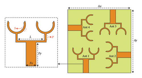
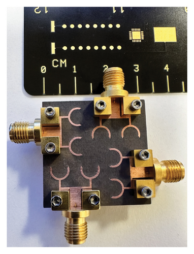
Although the designs reported above offer high isolation (with the use of some isolation enhancement networks) and moderate gain, they suffer due to their large, complex, and bulky structures. Based on the observations, the primary objective of this research is to design a simple planar structure that offers high gain and enough bandwidth to cover the 28 GHz frequency band. To achieve this, an array of 1 × 2 crescent-shaped patch antennas is designed, which resonates at 28.18 GHz. As all four elements are arranged in an orthogonal manner, this leads to a high isolation level of >22.5 dB between adjacent elements, while for the diagonal antenna elements, the isolation is observed to be greater than 32.5 dB. On the basis of the results, it can be said that the proposed MIMO antenna has the potential to be used for mm-wave applications, especially for the 28 GHz frequency band.
2. Quad-Port MIMO Antenna
2.1. Characteristics of Single Radiating Element
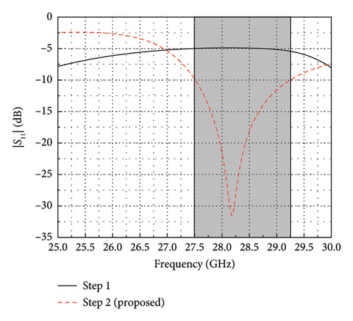
Before evaluating MIMO antenna performance characteristics, the design and characteristics of the single radiating element, which consists of a 1 × 2 array, are explained. The proposed 1 × 2 array is developed in two major steps. In the first step, a 1 × 2 array of ring elements is designed, and in the second step, an array of semi-ring (crescent-shaped) radiators is designed, as shown in Figures 3(a) and 3(b). The reflection coefficient (|S11|) response of both design stages is shown in Figure 3(c). It is observed that the stage 1 antenna is unable to resonate for the band of interest. As the patch shape is modified to a crescent shape, one can note that the array resonates well for the 28 GHz (27.5–29.25 GHz) frequency band, as shown in Figure 3(c).


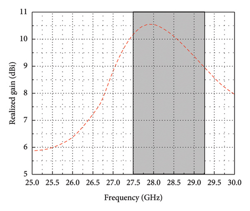
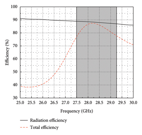
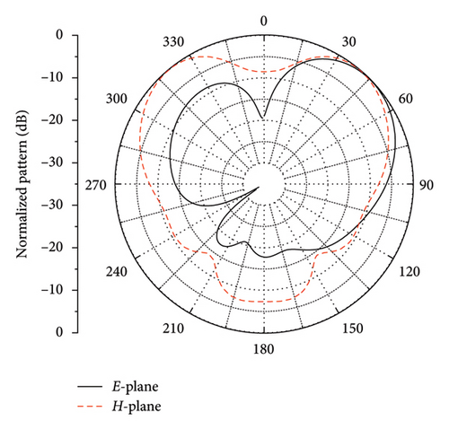
The realized gain, radiation efficiency, and total efficiency of the single MIMO element are given in Figures 4(a) and 4(b). An average gain of 9 dBi is observed in the operating bandwidth, while the peak gain of 10.5 dBi is observed at 28 GHz, as shown in Figure 4(a). In addition, the radiation efficiency and total efficiency of the designed 1 × 2 array are observed to be greater than 85% and 75%, respectively, in the operating bandwidth (see Figure 4(b)). The simulated normalized radiation patterns of MIMO’s single element at 28 GHz are shown in Figure 4(c). For the E-plane, the pattern tilts toward 47°, which can be associated with the phase mismatch at the divider output ports. On the other hand, the H-plane pattern shows a butterfly-like pattern, where the beam is directed toward ±47°.
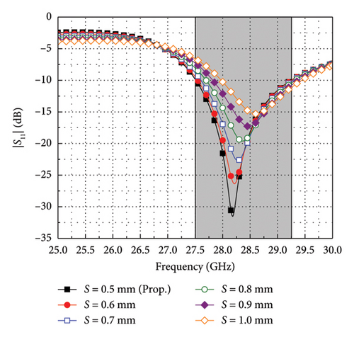
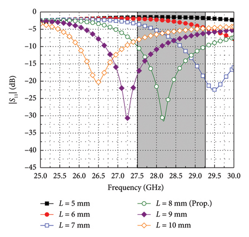
To tune the antenna response at the desired frequency, a parametric sweep is organized where the most crucial parameters of the radiating element are changed, and their effect is observed on the antenna’s |S11|. The parameters used for the study are the width (S) of the crescent-shaped radiating element and the length (L) of the feed transition. Parameter S varies in five steps (from 0.5 to 1.0 mm), while parameter L varies in six steps (from 5 to 10 mm), and the outcomes are depicted in Figures 5(a) and 5(b). As the value of S changed from 0.5 to 1.0 mm, three major changes were observed: a shift in the resonant frequency, bandwidth getting narrower, and degradation in the impedance matching, as shown in Figure 5(a). On the other hand, for lower L values, i.e., 5 and 6 mm, impedance mismatch is observed in the desired frequency band, as shown in Figure 5(b). As the value of L increased from 7 to 10 mm, a shift in the resonant frequency is observed with good impedance matching, as shown in Figure 5(b). For S = 0.5 mm, the designed 1 × 2 array offers maximum impedance matching and bandwidth, while for L = 8 mm, the antenna element provides resonance around the desired frequency band, i.e., 28 GHz. Additionally, by adjusting the value of S and L, one can tune the antenna response for desired frequency applications.
2.2. MIMO Antenna Characteristics
2.2.1. S-Parameters
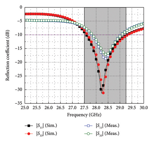
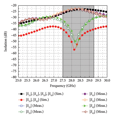
In Figure 6, to validate the findings, the measured S-parameters from the developed prototype are plotted alongside simulations. The measured S-parameters are obtained through a precision network analyzer (PNA) E8363C. Note that the reflection coefficient response is plotted only for two diagonal resonators, i.e., Ant 1 & 3, and it is observed that the results are well aligned with simulations, as shown in Figure 6(a). A slight shift in the resonant frequency is seen, and the measured bandwidth is narrower compared to the simulations. This slight variation in the results may arise because of fabrication tolerances, connector and cable losses, etc. Figure 6(b) shows the comparison between simulated and measured isolation performance. The isolation is measured by exciting two antenna elements at a time. From the plots, one can note that the measured isolation performance perfectly matches the simulations, as shown in Figure 6(b). The isolation among adjacent radiating elements is greater than 22.5 dB, and it is greater than 32.5 dB between diagonal elements.
2.2.2. Surface Current
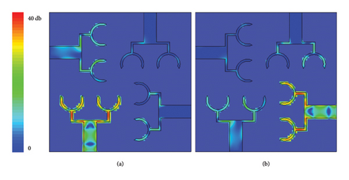
To further describe the self-isolated behavior of the proposed configuration, surface currents are plotted by exciting Ant 1 and Ant 2, as shown in Figure 7. Figure 7(a) shows a surface current plot when Ant 1 is excited. Notably, the orthogonal configuration of the antenna design naturally provides isolation between elements. This isolation is achieved through the phenomenon of destructive interference, where currents from adjacent elements cancel each other out. This inherent feature minimizes interference between antennas, enhancing their individual performance within the MIMO system. The same kind of behavior is noted for Ant 2 (see Figure 7(b)).
2.2.3. Radiation Characteristics
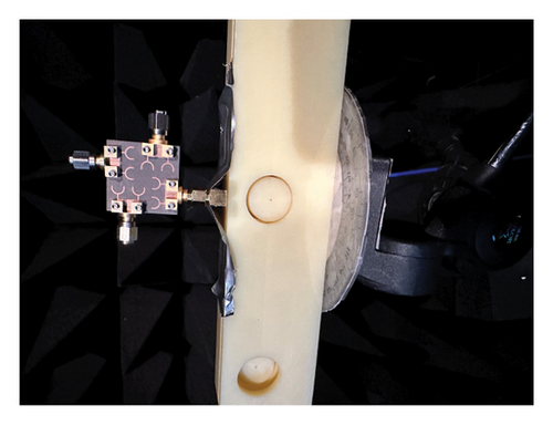
The far-field radiation patterns of the proposed MIMO antenna were measured in an anechoic chamber, where the antenna-under-test (AUT) was mounted on a turntable following standard procedure (see Figure 8). The radiation patterns are measured for Ant 1 and Ant 2 to verify the polarization diversity properties.
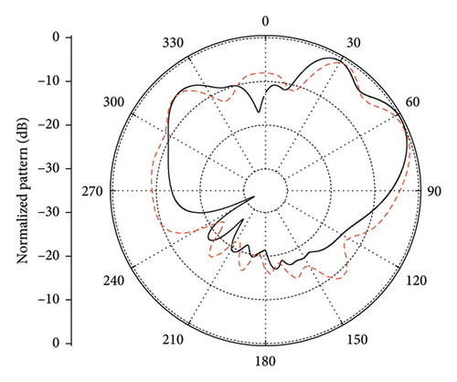
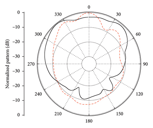
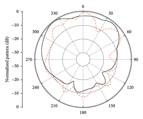
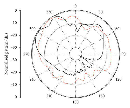
The E- and H-plane radiation patterns at 28.25 GHz for Ant 1 and Ant 2 are provided in Figure 9. In the case of Ant 1, the simulated and measured E-plane pattern is tilted toward 60°, as shown in Figure 9(a). On the other hand, the simulated H-plane pattern is somehow directional, where the main beam is directed toward 328°, while the measured pattern is directed toward 0°, as shown in Figure 9(b). The difference in the simulated and measured data may arise due to fabrication tolerances and scattering environment losses. Furthermore, to achieve polarization diversity, the antenna elements are arranged orthogonally to each other; therefore, the radiation characteristics should be the same. The only difference is that the E-plane pattern of Ant 1 is equal to the H-plane pattern of Ant 2, and vice versa [27]. This kind of behavior can be noted from the plots in Figures 9(c) and 9(d), where the radiation patterns of Ant 2 are plotted.
3. MIMO Parameters Analysis
The following sections provide detailed explanations of various MIMO performance parameters, including envelope correlation coefficient (ECC), diversity gain (DG), total active reflection coefficient (TARC), and channel capacity loss (CCL).
3.1. ECC and DG
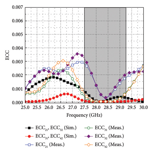
The derived ECC through the described method is less than 0.0005 at 28.25 GHz, while it is less than 0.003 for the rest of the band, as shown in Figure 10(a).
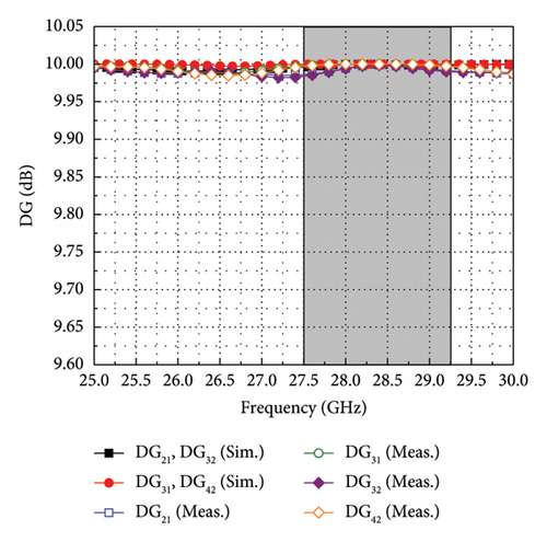
From Figure 10(b), the value of DG for both simulated and measured data is observed to be greater than 9.95 dB in the entire operating frequency.
3.2. TARC
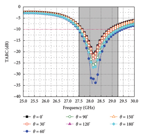
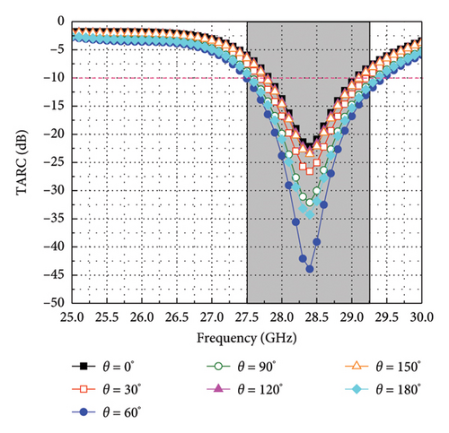
For the proposed design, the TARC is plotted by taking the S-parameter characteristics of adjacent antenna elements (Ant 1 and Ant 2) by varying θ from 0° to 180° with a step of 30° and shown in Figure 11. It can be observed that TARC bandwidth lies well within the reported operating bandwidth, i.e., 27.5–29.25 GHz for different input wave phases, as shown in Figure 11.
3.3. CCL
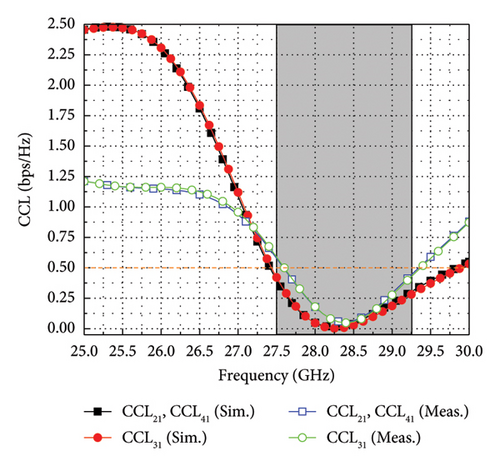
Table 1 presents a comparative analysis of published works of similar interest to the proposed MIMO antenna. The comparison is done with the MIMO antennas meant for 28 GHz frequency bands. Although the dimensions of the proposed MIMO antenna are large compared to the designs reported in [4, 17], it exhibits high gain compared to [4, 9, 13, 17, 19–21, 23, 24] and offers wide bandwidth compared to [6]. In addition, the MIMO antenna designs listed in Table 1 used decoupling networks and metasurface-based superstrates to achieve high isolation and high gain. As opposed to this, the proposed structure does not utilize any isolation or gain-enhancement network, which makes it superior to the previously presented designs. The comparative analysis highlights the proposed MIMO antenna as a strong candidate for future mm-wave Ku-band applications.
| Reference | Ports | Dimensions | Antenna footprint | Frequency band | Bandwidth | Isolation | Gain | ECC | CCL | |
|---|---|---|---|---|---|---|---|---|---|---|
| (mm2) | (λ2) | (mm2) | (GHz) | (GHz) | (dB) | (dBi) | (bps/Hz) | |||
| [4] | 4 | 30 × 43 | 2.55 × 3.65 | 1290 | 24.55–26.5 | 1.95 | > 30 | 10.27 | < 0.0001 | < 0.4 |
| [5] | 4 | 24 × 24 | 2.11 × 2.11 | 576 | 23.5–29.4 | 5.9 | > 22.5 | 10.44 | < 0.004 | < 0.5 |
| [6] | 4 | 30 × 35 | 2.80 × 3.26 | 1050 | 27.5–28.5 | 1.0 | > 40 | 12 | < 0.0003 | < 0.4 |
| [9] | 4 | 30 × 30 | 2.83 × 2.83 | 900 | 27.5–29 | 1.5 | > 28 | 5.5 | < 0.16 | N.A. |
| [13] | 4 | 25 × 25 | 2.22 × 2.22 | 625 | 25.28–28.02 | 2.74 | > 20 | 8.72 | < 0.0015 | N.A. |
| [17] | 4 | 40 × 35 | 3.74 × 3.27 | 1400 | 24.1–30.9 | 6.8 | > 30 | 6.5 | < 0.18 | < 0.25 |
| [18] | 2 | 26 × 10 | 2.38 × 0.91 | 260 | 25.25–29.85 | 4.6 | > 35 | 10.8 | < 0.001 | < 0.2 |
| [19] | 3 | 19 × 7 | 1.78 × 0.65 | 133 | 26.7–29.6 | 2.9 | > 21 | 6.3 | < 0.04 | < 0.3 |
| [20] | 4 | 16.2 × 16.2 | 1.45 × 1.45 | 262.44 | 24.25–29.5 | 5.25 | > 23.5 | 6.09 | < 0.002 | < 0.25 |
| [21] | 4 | 20 × 16 | 1.90 × 1.52 | 320 | 23.45–33.59 | 10.94 | > 25 | 5.65 | < 0.002 | N.A. |
| [22] | 2 | 30 × 15 | 1.40 × 2 | 450 | 26.95–29.5 | 2.55 | > 30 | 10.3 | < 0.0002 | < 0.4 |
| [23] | 4 | 20.48 × 20.48 | 1.98 × 1.98 | 419.43 | 25.21–32.34 | 7.13 | > 20 | 6.87 | < 0.006 | < 0.25 |
| [24] | 4 | 16 × 16 | 1.5 × 1.5 | 256 | 22.2–31.4 | 9.2 | > 22 | 5.98 | < 0.002 | < 0.2 |
| Prop. | 4 | 33 × 33 | 3.1 × 3.1 | 1089 | 27.5–29.25 | 1.75 | > 22.5 | 10.5 | < 0.003 | < 0.375 |
4. Conclusion
A novel four-element MIMO antenna design is introduced in this work for 28 GHz mm-wave 5G technology. The single radiator features a 1 × 2 array of crescent-shaped patch elements connected by a T-junction power-dividing network. It is observed that the single radiating elements offer a peak gain of 10.5 dBi with 6.21% fractional bandwidth. The quad-port MIMO configuration with polarization diversity promises enhanced CC. Notably, the proposed MIMO system showcases impressive self-isolationcharacterictics with isolation characteristics exceeding 22.5 dB across the operating bandwidth. Essential MIMO performance parameters fall within the operational limits. Comparative analysis with previously presented literature highlights the significance of the proposed design. Future work includes designing a massive MIMO configuration of the proposed antenna and studying the performance parameters along with the design of a sub-6 GHz MIMO antenna design.
Conflicts of Interest
The authors declare no conflicts of interest.
Author Contributions
Conceptualization, H.E., U.R., and M.U.T.; methodology, H.E. and U.R.; software, H.E., U.R., M.U.T., M.A., and A.D.A.; validation, H.Ş.S., M.A., and M.D.; formal analysis, H.E., H.Ş.S., M.A., and A.D.A.; resources, U.R., H.Ş.S., A.D.A., and M.A.; writing – original draft preparation, H.E., U.R., M.U.T., and M.A.; writing – review and editing, H.Ş.S., A.D.A., and M.A.; visualization, U.R.; supervision, H.Ş.S., A.D.A., and M.A.; project administration, H.Ş.S. and M.A.; funding acquisition, H.E., A.D.A., and M.A.
Funding
Princess Nourah bint Abdulrahman University Researchers Supporting Project number (PNURSP2025R747), Princess Nourah bint Abdulrahman University, Riyadh, Saudi Arabia.
Open Research
Data Availability Statement
The data that support the findings of this study are available from the corresponding author upon reasonable request.


