A Wideband Vivaldi Array With Enhanced Power Handling Capacity
Abstract
This paper proposes an all-metal Vivaldi array based on the tight coupling effect with enhanced power handling capacity (PHC). To achieve this, L29 connectors and enlarged parallel-plate waveguides are strategically implemented to reduce localized electric field intensity. By optimizing the reflective cavity dimensions, half-wavelength resonance within the operational bandwidth is effectively suppressed. Furthermore, extending the arms of edge elements mitigates the E-plane truncation effect. The designed array demonstrates an active voltage standing wave ratio (VSWR) below 2 across 0.55–4.17 GHz and below 3 within 0.53–4.15 GHz while scanning up to 45° in both E- and H-planes. A prototype 8 × 10 array (370 × 240 mm) was fabricated and tested, achieving a PHC of ≥ 10.1 MW at broadside and ≥ 7.25 MW at 45° scan angles. Measured results align closely with simulations, validating the design’s robustness for high-power microwave (HPM) applications.
1. Introduction
With the advancement of high-power microwave (HPM) technologies, the transition from vacuum tubes to electronic devices for generating HPM signals has gradually emerged as a significant development direction. For instance, all-solid-state HPM sources based on photoconductive semiconductor switches (PCSSs) are capable of producing microwave signals at the megawatt level, and they also exhibit frequency agility and adjustable phase capabilities [1, 2]. This evolution necessitates the development of antennas that not only have high power handling capacity (PHC) but also offer wide bandwidth and large scanning angles.
Compared to single Vivaldi antennas, which achieve broad bandwidth through exponentially tapered arms [3], Vivaldi arrays based on small elements utilize the coupling effects between adjacent elements to enable radiation in the low-frequency band. Such arrays can achieve a wide scanning angle, as the scanning performance is closely related to the spacing between the elements [4]. Compared to other ultra-wideband arrays, such as tightly coupled arrays [5] and spiral arrays [6], Vivaldi arrays exhibit a more concise and compact planar structure.
Traditional HPM broadband antennas, such as impulse radiation antennas (IRAs), large TEM horns, and large spiral antennas, provide advantages in manufacturing simplicity and high PHC [7–9]. However, they face challenges in meeting the increasing demands for broad bandwidth and scanning capacity associated with the development of solid-state HPM technology. In contrast, Vivaldi arrays can achieve wideband and scanning capabilities, aligning well with the requirements of solid-state HPM applications. This positions them as promising candidates for effective implementation in solid-state HPM technologies.
Vivaldi arrays can be constructed in either a dielectric form or a full-metal form [10, 11]. Opting for the full-metal configuration helps avoid the issue of metal-dielectric-air triple junctions, which can lead to polarization of the dielectric near the contact, resulting in the accumulation of space charges that may cause dielectric flashover in the presence of HPM radiation [12]. The full-metal Vivaldi array designed by other scholars typically aims to reduce dielectric losses and enhance the structural strength [13, 14]. However, existing designs do not consider PHC and the structure of the arrays limits its application in HPM sources, which are typically employed for anti-drone systems.
In this paper, a full-metal Vivaldi array based on the tight coupling effect is proposed. The limiting factors of the PHC in Vivaldi arrays are analyzed, and improvements are suggested. By adjusting the dimensions of the reflective cavity, wideband frequency coverage is achieved and half-wave resonance is eliminated. Additionally, by extending one arm of the edge elements in the E-plane, the edge truncation effect in the E-plane is mitigated. Furthermore, the produced Vivaldi array exhibits high PHC, wideband frequency coverage, and wide-angle scanning capabilities.
2. Design of Vivaldi Array
2.1. Basic Structure of the Elements
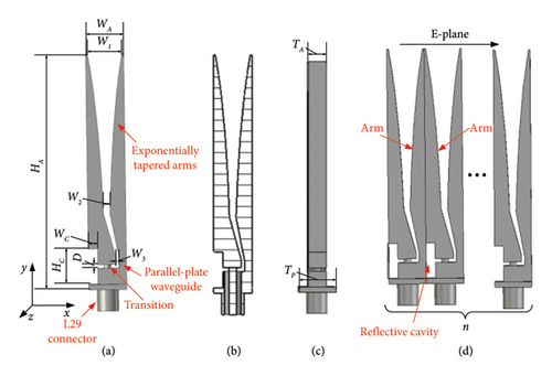
In other all-metal Vivaldi arrays [13, 15, 16], the connectors and the parallel-plate waveguides are the regions where the electric field is strongest, while the PHC is weakest in these areas. To reduce the electric field in the elements, L29 connectors with an outer diameter of 16 mm and an inner diameter of 7 mm are employed. Additionally, the spacing of the parallel-plate waveguides is adjusted to a larger value. A resonance occurs due to the constraints imposed on the reflective cavity width WC by the L29 connectors. An analysis of the resonance is conducted, and the size of the reflective cavities is adjusted accordingly. The parameter values are provided in Figure 1.
2.2. Principle of the Vivaldi Array
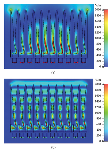
The Vivaldi array proposed in this paper achieves wide bandwidth and broad scanning angles primarily by tight coupling effects between adjacent elements. Low-frequency radiation is realized through the coupling effects among adjacent elements, while at higher frequencies, radiation is realized primarily through single elements, contributing to their broadband performance. Since the elements are connected in the E-plane, the currents can extend into adjacent ones, allowing multiple elements to collectively radiate at low frequencies. A model was established using CST, as shown in Figure 1(c), with n = 10, periodic boundary conditions set in the H-plane (z-axis), and the reflective cavity of the edge element formed between the notch and an additional 1 mm metallic structure. The simulation results for the E-plane electric field distribution are depicted in Figure 2. At 0.5 GHz, the electric field contours indicate that multiple elements work together to form a wave, demonstrating that low-frequency radiation is primarily achieved through the collective action of these elements. In contrast, at 4 GHz, the electric field contours remain largely independent among individual elements, indicating that, at higher frequencies, radiation is predominantly generated by single elements.
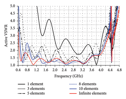
In order to explore the impact of the number of elements on the performance of the array, the active voltage standing wave ratio (VSWR) of the central element is analyzed in the 1 × n array depicted in Figure 1(c). The active VSWR refers to the VSWR of a specified element when all elements in the array are fed simultaneously. The active VSWR of the elements in an infinite array is obtained from the model in Figure 1(a) simulated using CST with periodic boundary conditions applied to both the E-plane and H-plane.
The simulation results, illustrated in Figure 3, indicate that as the number of elements n increases, the active VSWR of the central element decreases significantly, particularly in the low-frequency range. This suggests that the Vivaldi array requires a sufficient number of elements to achieve effective radiation in the low-frequency band. The figure also illustrates that the performance in the low-frequency range is optimal as the number of elements approaches infinity. However, it is impractical to manufacture an infinitely large array. With 10 elements, the performance meets the requirements for the low-frequency range, and further increases in the array size would lead to higher costs. Therefore, we have chosen to employ a finite array with n = 10.
Considering that the Vivaldi array primarily depends on the coupling effects among elements in the E-plane to enhance bandwidth at low frequencies, the number of elements in the H-plane has a minimal impact on its performance. Nonetheless, to investigate the scanning characteristics in the H-plane, we have arranged 8 elements in the H-plane.
2.3. Suppression of Half-Wavelength Resonance
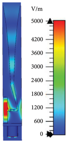
The width of the reflective cavity, Wc, is constrained by the large size of the L29 coaxial connector, necessitating an increase in its height, Hc, to achieve broad impedance matching. However, as Hc increases, resonance occurs at a specific frequency within the array. Taking Hc = 50 mm as an example, Figure 4 illustrates that resonance occurs at 2.95 GHz. Figure 5 demonstrates the electric field distribution at this frequency, revealing a significant enhancement of the field within the reflective cavity, indicating that this resonance is driven by the reflective cavity.
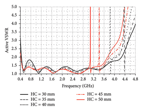
When HC = 50 mm, using formula (2), the calculated resonant frequency is approximately 3 GHz, which aligns closely with the simulated result of 2.95 GHz. The slight discrepancy is caused by the opening of the reflective cavity. The resonant frequencies obtained for other HC values using formula (2) closely approximate those from simulations, thus confirming that this resonance is a half-wavelength resonance.
Additionally, the parameter sweep shown in Figure 4 indicates that as HC increases, the standing wave characteristics of the Vivaldi element improve in the low-frequency range. Therefore, it is essential to select a larger value for HC while avoiding interference from the half-wavelength resonance within the operational bandwidth. HC = 33 mm is chosen in this paper, ensuring that the resonant frequency does not interfere with the operational bandwidth while maintaining good standing wave characteristics.
2.4. Mitigation of Edge Truncation Effect
The active VSWR of the central elements in a sufficiently large array is comparable to that of elements in an infinite array, as shown in Figure 3. Conversely, the performance of edge elements differs from that of elements in an infinite array due to the lack of adjacent elements, resulting in the edge truncation effect. Especially in the E-plane, the Vivaldi array exploits the coupling effect to broaden the bandwidth; the lack of this coupling effect notably affects the characteristics of the edge elements in the E-plane. Figure 6 presents the active VSWR for edge and central elements in the E-plane obtained from the simulation of the model as shown in Figure 1(c) for n = 10. In the figure, the original element 1 and original element 5 correspond to the edge and central elements, respectively. The active VSWR of original element 1 is significantly higher than that of original element 5, particularly notable at 0.65 GHz, where the active VSWR of the original element 1 exceeds 3.5. Clearly, it is necessary to implement strategies to enhance the standing wave characteristics of edge elements. Common strategies to mitigate these edge truncation effects include incorporating resistive loads or virtual elements [17], optimizing the structural design of edge elements [18], and utilizing specialized edge elements or artificial electromagnetic boundaries [19]. However, resistive loading is typically suitable for dielectric-based arrays, whereas the use of specialized edge elements or artificial electromagnetic boundaries would increase the complexity of the array and requires additional PHC considerations. To address this issue, the method of extending the arms of the edge elements was chosen in this paper, as it provides a simple and effective solution.
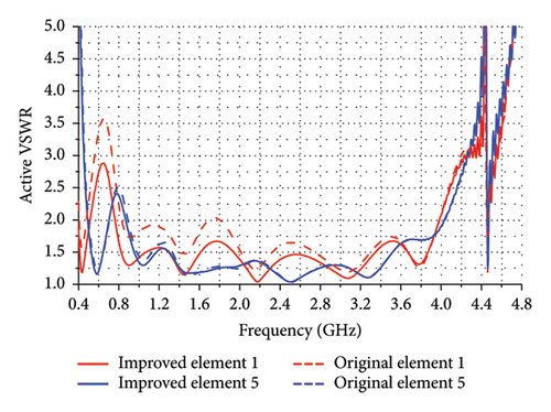
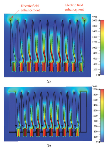
Figure 7(a) illustrates the electric field distribution obtained from the simulation of the original array based on the model shown in Figure 1(c) when n = 10. It is evident that there is a significant enhancement of the electric field strength at the top of the arms of the edge elements. This enhancement is primarily attributed to the abrupt termination of the elements, as the continuous current flowing along the Vivaldi elements is abruptly terminated at the arms of the edge elements. Clearly, this enhanced electric field can negatively affect the performance of the edge elements. In the improved array, the edge arms are extended by 20 cm, as depicted in Figure 8. The electric field distribution is shown in Figure 7(b), where a more uniform distribution of electric field strength is apparent along the extended arms, effectively eliminating the previously observed enhancement.
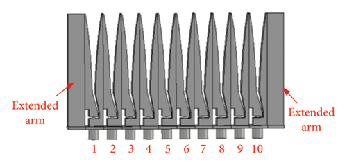
The active VSWR of the Vivaldi array as shown in Figure 8, simulated by CST, is illustrated in Figure 6. In this figure, the serial numbers of the elements are annotated, with improved element 1 and improved element 5 referring to the edge and central elements, respectively. The simulation results indicate that extending the arms significantly reduces the active VSWR for element 1, particularly in the low-frequency range. Specifically, the active VSWR for element 1 decreases from 3.58 to below 2.88 after the arms are extended. This suggests that extending the arms effectively enhances the performance of the edge element in the E-plane. The notable improvement at low frequencies is attributed to the longer wavelength, which makes it more susceptible to edge truncation effects. Additionally, the active VSWR for element 5 decreases from 2.52 to below 2.40, indicating that extending the arms also positively impacts the performance of the central elements.
2.5. PHC of the Array
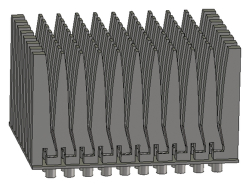
The proposed array utilizes Vivaldi elements to form an 8 × 10 configuration, as shown in Figure 9. Additionally, the E-plane arms of the edge elements have been extended, as depicted in Figure 8.
Simulating with CST, the electric field distribution of the array was obtained, allowing for the extraction of the maximum field strength at the corresponding frequency points within the array. To maintain maximum power capacity, uniform excitation was applied to all elements. When the power injected into each port is 0.5 W, resulting in a total power injection of 40 W for the entire Vivaldi array with 80 ports, the maximum field strengths are illustrated in Figure 10. Within the frequency range of 0.5–4 GHz, the maximum field strengths of the array were found to be 5965, 6176, 6571, 6362, and 7042 V/m, for broadside, E-plane scans at 30° and 45° as well as H-plane scans at 30° and 45°, respectively.
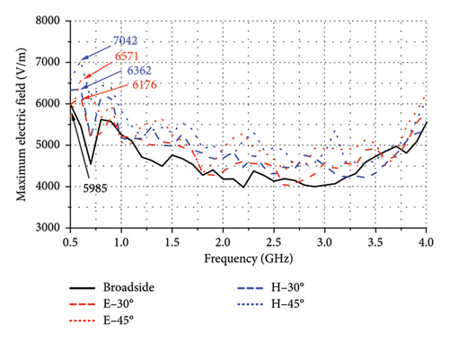
In air, the breakdown electric field threshold is 30 kV/cm. Using formula (3), the PHC of entire Vivaldi array is calculated to be at least 10.1, 9.43, 8.33, 8.89, and 7.25 MW at broadside and E-plane scans at 30° and 45°, as well as H-plane at 30° and 45°, respectively.
3. Fabrication and Measurement Results
3.1. Fabrication of the Proposed Vivaldi Array
To validate the performance of the proposed Vivaldi array, an 8 × 10 array was produced according to the simulation model shown in Figure 9. The assembled array is illustrated in Figure 11. Testing was conducted, and the results were compared and analyzed against the simulation outcomes.

3.2. Active VSWR
To validate the performance of the element, a feed port located at the center of the array was selected for testing, as the characteristics of the elements in this position are roughly in agreement with those of an infinite array. The feed port chosen for testing was the one in the fifth column of the sixth row of the array. The measured active VSWR during E-plane scanning is indicated by the red line in Figure 12(a), while the active VSWR during H-plane scanning is represented by the blue line in Figure 12(b). The results demonstrate that the active VSWR remains < 2.1 across the frequency range of 0.55–4.17 GHz at broadside radiation. Furthermore, within the frequency band of 0.53–4.15 GHz, both the E-plane scans at 30° and 45° and the H-plane scans at 30° and 45° meet the criterion of active VSWR < 3. During scanning, the active VSWR exhibits relatively higher values due to mutual coupling effects, yet remains < 3, which is a performance level well within acceptable operational limits.
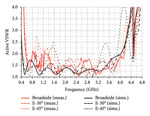
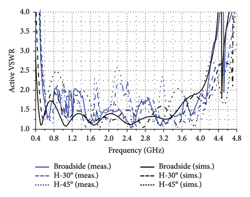
To analyze the test results and to evaluate the standing wave characteristics of the proposed Vivaldi element by simulation, a model as depicted in Figure 1 was established using CST, with periodic boundary conditions applied around its periphery. These boundary conditions were implemented to properly account for coupling effects between adjacent elements. The active VSWR obtained during the E-plane and H-plane scanning simulation is represented by the black lines in Figures 12(a) and 12(b), respectively. The simulation results indicate that the active VSWR < 2 across the frequency range of 0.43–4.03 GHz at broadside radiation. Furthermore, within the frequency range of 0.51–3.98 GHz, the scans at 30° and 45° in both the E-plane and H-plane satisfy the standard of an active VSWR < 3.
Simulation results show a broader low-frequency band in the active VSWR compared to the test results. It can be attributed to the edge truncation effects associated with the infinite array of the fabrication. Furthermore, the test results indicate a resonance at 4.50 GHz during broadside radiation, which is close to the simulation result of 4.45 GHz and the calculated result of 4.54 GHz from equation (2), suggesting that the resonance observed is indeed a half-wavelength resonance.
3.3. Mutual Coupling Effect
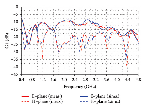
Since the Vivaldi array proposed in this paper relies on tight coupling effects, especially in the E-plane, to achieve bandwidth expansion, there will be significant mutual coupling between the adjacent elements. Figure 13 shows the S21 parameters between the central element of the array and its adjacent elements in the E-plane and H-plane. It can be observed that the measured results are generally consistent with the simulation. S21 between adjacent elements in the E-plane is significantly higher than that in the H-plane, indicating that the array primarily utilizes the strong coupling effect in the E-plane to achieve bandwidth expansion. This finding is also consistent with the earlier theoretical analysis.
3.4. Radiation Pattern
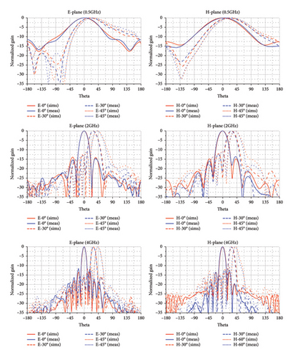
The far-field radiation patterns of the 8 × 10 prototype were measured using the unit excitation active element pattern (UEAEP) method in a microwave anechoic chamber [22]. The UEAEP method was adopted because it inherently accounts for mutual coupling effects between elements. The measured E-plane and H-plane scanning radiation patterns are represented by the blue lines in Figure 14, and they are compared with the simulated radiation patterns indicated by the red lines, where the simulation was performed for the entire array to ensure inclusion of mutual coupling effects. This comparison demonstrates that the measured sidelobe levels are low and are in good agreement with the simulation results. At frequencies of 0.5, 2, and 4 GHz, the radiation patterns exhibit normal characteristics, with sidelobes below −10 dB and no grating lobes detected. This indicates that the array can achieve good radiation performance within a 45° scanning range in both the E-plane and H-plane.
3.5. HPM Experiments
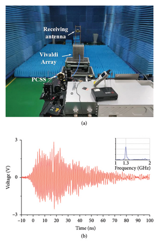
To validate the applicability of the proposed array in HPM applications, experiments were carried out using a central element of the array in conjunction with an existing experimental platform. As shown in Figure 15(a), a microwave generation system based on 4H-SiC PCSSs was utilized, which features frequency-agile and adjustable phase capabilities with an output power of 0.1 MW. Currently, no higher power all-solid-state sources are available in our laboratory. For more detailed information about the generation system, refer to reference [2]. HPM experiments were conducted at selected frequency points with the system connected to a central element of the array. Throughout the experiments, no breakdown occurred in the array, and the waveforms observed on the oscilloscope remained normal. Figure 15(b) displays the received waveform and spectrum when the microwave generation system produced a 1.3 GHz microwave signal with an energy of 0.1 MW and a pulse width of 80 ns. The results confirm that the element can withstand at least 0.1 MW, implying the full array can withstand at least 8 MW with a plane size of 390 × 280 mm. This demonstrates that the proposed Vivaldi array is suitable for current all-solid-state sources.
4. Conclusion
This paper presents a full-metal Vivaldi array based on tight coupling effect. The design employs an L29 coaxial connector combined with expanded parallel-plate waveguide spacing and optimized reflective cavity dimensions to achieve high PHC, broadband performance, and wide scanning angles. The half-wavelength resonance within the operational band is suppressed by cavity dimension adjustments. Furthermore, extending the arms of E-plane edge elements effectively mitigates truncation effects. An 8 × 10 prototype was fabricated, demonstrating operational bandwidth of 0.55–4.17 GHz and scanning capabilities of ±45° in both E- and H-planes within 0.53–4.15 GHz. The array exhibits a PHC of 10.1 MW at broadside and 7.25 MW during 45° scanning, validating its suitability for phased-array HPM applications, especially in anti-drone.
Conflicts of Interest
The authors declare no conflicts of interest.
Funding
This work was supported in part by the National Natural Science Foundation of China under grant nos. 62071477 and 62101577, and in part by the Natural Science Foundation of Hunan Province under grant no. 2021JJ40660.
Acknowledgments
This work was supported in part by the National Natural Science Foundation of China under grant nos. 62071477 and 62101577, and in part by the Natural Science Foundation of Hunan Province under grant no. 2021JJ40660.
Open Research
Data Availability Statement
The data that support the findings of this study are available on request from the corresponding author. The data are not publicly available due to privacy or ethical restrictions.


