Investigation of a Rectangular Dielectric Resonator Antenna Working in Higher Order Modes Using Perturbation Theory
Abstract
Dielectric resonator antennas (DRAs) operating in higher order modes provide wideband, enhanced gain, and circularly polarized performance. This paper presents a simple perturbation theory for predicting the resonant frequency of higher order modes in perturbed rectangular DRAs (RDRAs). The proposed theory has been validated for isolated RDRA, two-layer DRA, and RDRA with rectangular- and cylindrical-shaped perturbations. To determine the accuracy of the proposed theory, the frequency computed from it is compared to simulated and measured results of higher order mode perturbed antennas available in the literature. The proposed theory can be easily applied to the design of perturbed DRAs that operate at higher order modes. Also, the theory can be extended to compute other antenna parameters.
1. Introduction
The dielectric resonator antenna (DRA) is a potential candidate for future wireless communication systems, particularly at microwave and millimeter-wave frequencies, because of its inherent advantages of wide bandwidth and lower losses [1]. DRA can be implemented in a variety of shapes, including circular, rectangular, spherical, and conical [2, 3]. Among all of these shapes, the rectangular shape of the dielectric resonator drew the most attention due to its numerous features that make antenna implementation simple and efficient. The use of rectangular dielectric resonator allows for greater freedom in selecting the resonant frequency of the antenna [4]. Also, the rectangular DRA (RDRA) [5] offers less cross-polarization and can be easily used in arrays [6]. Furthermore, it is simple to excite accurately predictable resonant modes and design a RDRA with the correct dimensions based on the required operating mode. The term “required operating mode” is important in this context as it refers to obtaining the desired operating and radiation characteristics of the antenna. The radiation behavior of an antenna can be accurately defined if its operating modes are completely known. A number of research articles are available in the literature, which reported on the design of DRA operating with the fundamental and multiple higher order modes [2, 3, 7]. It is already known that a RDRA operating in higher order modes provides a higher gain than an antenna operating in fundamental mode [8]. In advanced wireless communication systems that require high data transfer rates over long distances, obtaining high gain and wide impedance bandwidth is required [9].
There are several methods in the literature that describe gain and bandwidth enhancement techniques [10, 11]. Moreover, the perturbation technique has been investigated for obtaining high gain and wideband response. The concept of DRAs with material wall perturbation in the form of vias and metal wall perturbation in the form of metal strips is also used to design band notch filtering [12], wide stop band filtering [13], and circularly polarized DRAs [14, 15]. The calculation of the resonant frequencies of the operating modes of the perturbed RDRA (PRDRA) has been a long-standing research topic, with a brief discussion of techniques provided in [16, 17]. However, unlike higher order modes, the perturbation approach is capable of easily calculating the resonant frequency of the fundamental mode. No research has been conducted on calculating the resonant frequency of the higher order mode. And, as previously discussed, the generation of higher order modes in the RDRA can offer enhanced characteristics that can make future communication systems fluent with high-end technology. In the literature, two-layer inhomogeneous structures are simulated and fabricated to generate higher order modes at lower frequencies while increasing gain and bandwidth. These are the principles of material perturbation. These reported DRAs are simulated and fabricated, but no specific theory is provided for the change in resonant frequency of the perturbed structure. In this paper, the authors proposed a very simple and accurate perturbation theory for predicting the resonant frequency of higher order modes in such inhomogeneous PRDRA structures.
This study presents a method for calculating the resonant frequency of a PRDRA operating in higher order modes. For the first time, perturbation theory is proposed in this paper for higher order RDRAs and PRDRAs. The perturbation shape of RDRA is rectangular or cylindrical. The higher order mode frequencies associated with each type of perturbation are computed using the proposed theory and compared to simulated and measured frequencies of PRDRAs coated with dielectric materials. It also explains how the permittivity and perturbation position are used to enhance the bandwidth and gain. The main advantage of the proposed theory is that it bridges the gap between simulated and measured results by providing the precise dimension and position of perturbation required to design an antenna with the desired performance. In the future, the theory can be applied to RDRA subjected to spherical-shaped perturbations.
2. Theory
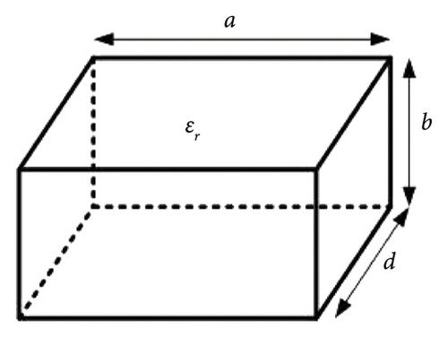
The perturbation concept is used in the design of inhomogeneous DRAs. Material perturbation and heterogeneous DRAs include two-layer DRAs, stacked DRAs, and RDRA with rectangular- and cylindrical-shaped inserts. The quasi-static approximation is used at a dielectric-dielectric discontinuity, and the continuity of electric field intensity in the perturbed region and the original DRA is maintained.
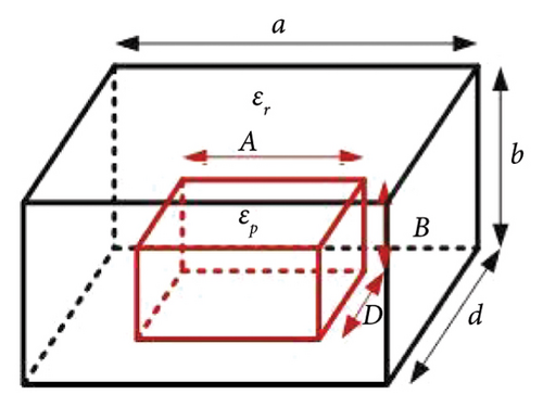
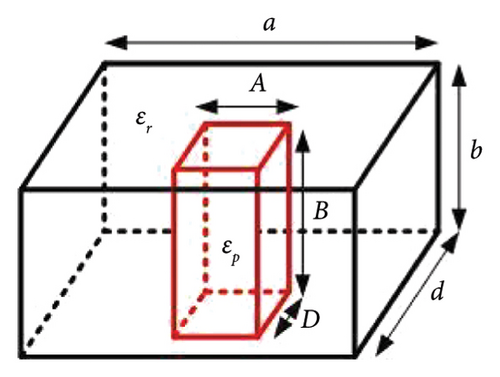
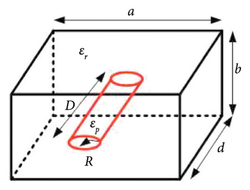
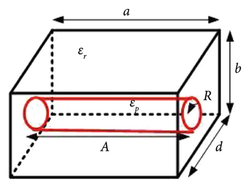
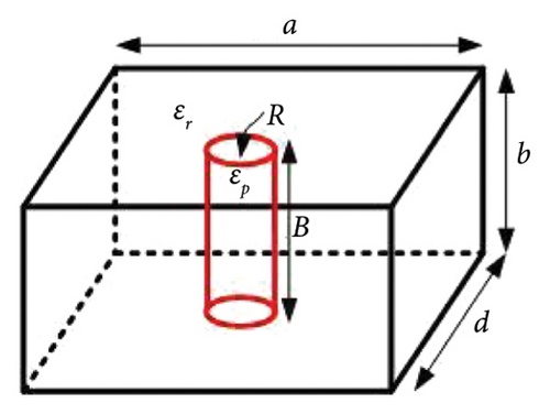
The perturbation theory for higher order RDRA modes with rectangular- and cylindrical-shaped perturbations is shown in Figures 2 and 3. Figure 2 depicts the RDRA with a rectangular-shaped perturbation, while Figure 3 depicts the RDRA with a cylindrical-shaped material perturbation. The perturbed cylinder is concentric with the RDRA. Table 1 shows the quasi-static approximation for the electric field relation at the dielectric-dielectric discontinuity, as well as the perturbation approach for all perturbation cases. Equation (4) is used to calculate the resonant frequency of the mode.
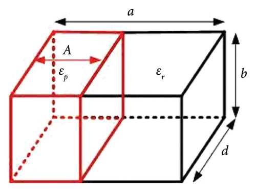
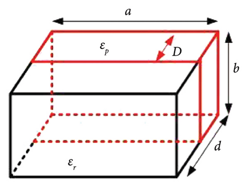
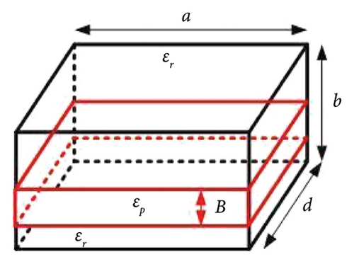
| Shape of perturbation (dimensions) | Structure | Quasi-static approximation electric field intensity relationship between perturbed region (EP) and original region (E0) | Perturbation approach |
|---|---|---|---|
| Rectangular (A × b × d) | Figure 2(a) | EP = E0 | (Δfmn)/fp = K(A/a)((Δε)/ɛr)((1+sin c(kxA)cos(kx(A − a)))/(1 + sin c(kxa))) |
| Rectangular (a × b × D) | Figure 2(b) | EP = E0 | (Δfmn)/fp = K(D/d)((Δε)/ɛr) |
| Rectangular (a × B × d) | Figure 2(c) | (Δfmn)/fp = (K/2)(B/b)((Δε)/ɛp) | |
| Rectangular (A × B × D) | Figure 2(d) | EP = E0 | (Δfmn)/fp = K((Δε)/ɛr)(BD(a − A)/abd)((1+sinc(kx(a − A)))/(1 + sinc(kxa))) |
| Rectangular (A × B × D) | Figure 2(e) | EP = E0 | (Δfmn)/fp = K(ABD/abd)((Δε)/ɛr) |
| Cylindrical (radius = R, height = A = a) | Figure 3(a) | EP = (2ɛr)/(ɛp + ɛr)E0 | (Δfmn)/fp = 2K(πR2/bd)((Δε)/(ɛr + ɛp)) |
| Cylindrical (radius = R, height = D = d) | Figure 3(b) | EP = (2ɛr)/(ɛp + ɛr)E0 | (Δfmn)/fp = 2K(πR2/ab)((Δε)/(ɛr + ɛp)) |
| Cylindrical (radius = R, height = B = b) | Figure 3(c) | EP = E0 | (Δfmn)/fp = K(πR2/ad)((Δε)/ɛr) |
In Table 1, and Δε = ɛr − ɛp, and a, b, and d are the dimensions of RDRA along the x, y, and z directions, respectively. A, B, and D are the dimensions of the perturbed structure in the x, y, and z directions for RDRA. The dimensions of perturbed structures along the x, y, and z directions are A, B, and D, respectively, for RDRA with rectangular-shaped perturbation. R is the radius of the cylinder and sphere for the cylindrical- and spherical-shaped perturbed regions. Table 1 contains simple equations that can be used to predict the resonant frequency of higher order modes of PRDRA. The proposed theory is verified and validated with the simulated and fabricated PRDRA results.
3. Results
- (i)
Validation of higher order modes for unperturbed RDRA
- (ii)
Validation of higher order PRDRA modes with rectangular-shaped perturbations
- (iii)
Validation of higher order PRDRA modes using cylindrical-shaped perturbations
In Table 2, the proposed theory is used to compute the resonant frequency of an unperturbed RDRA. In [21], the RDRA with different dimensions is excited in higher order modes. The calculated errors between frequencies are within the acceptable range.
| References | Mode | ɛr | Dimensions (a × b × d) (mm3) | fsim (GHz) | fmeas (GHz) | fprop (GHz) | % Δfsim = (fsim − fprop)/fsim | %Δfmeas = (fmeas − fprop)/fmeas |
|---|---|---|---|---|---|---|---|---|
| [21] | 12.7 | 12 × 20 × 8 | 8.44 | 8.30 | 8.6977 | −3.05 | −4.79 | |
| 12.7 | 12 × 20 × 8 | 12.18 | 12.01 | 12.5660 | −3.17 | −4.63 | ||
| 12.7 | 8 × 24 × 10 | 7.54 | 7.24 | 7.7373 | −2.62 | −6.87 | ||
| 12.7 | 8 × 24 × 10 | 10.52 | 10.25 | 10.391 | 1.23 | −1.38 | ||
| 12.7 | 8 × 20 × 12 | 10.03 | 9.7 | 10.2767 | −2.46 | −5.95 | ||
| 12.7 | 8 × 20 × 12 | 10.84 | 10.40 | 10.775 | 0.60 | −3.61 | ||
| 12.7 | 12 × 16 × 10 | 11.54 | 11.25 | 11.8795 | −2.94 | −5.60 | ||
| 12.7 | 12 × 16 × 10 | 10.70 | 10.40 | 10.91 | −1.96 | −4.90 | ||
| 12.7 | 10 × 24 × 8 | 11.85 | 11.62 | 12.2491 | −3.37 | −5.41 | ||
| [29] | 10 | 18 × 58 × 20 | 3.52 | 3.54 | 3.4395 | 2.29 | 2.84 | |
| 10 | 18 × 58 × 20 | 4.28 | 4.15 | 3.9058 | −0.25 | −3.39 | ||
| [30] | 10 | 3.96 × 3.96 × 12.2 | 24.06 | 23.86 | 23.9744 | 0.36 | −0.48 | |
| 10 | 4.27 × 4.27 × 21.36 | 24.05 | 23.87 | 24.0262 | 0.09 | −0.65 | ||
| [31] | 12 | 28 × 32 × 24 | 3.51 | — | 3.4824 | 0.79 | — | |
| 12 | 28 × 32 × 24 | 3.76 | — | 3.7431 | 0.45 | — | ||
| 12 | 27 × 33 × 24 | 3.44 | — | 3.4330 | 0.20 | — | ||
| 12 | 27 × 33 × 24 | 3.82 | — | 3.8265 | −0.17 | — | ||
| 12 | 30 × 30 × 24 | 3.62 | — | 3.5992 | 0.58 | — | ||
| 12 | 30 × 30 × 24 | 3.62 | — | 3.5992 | 0.58 | — | ||
| [8] | 10 | 6 × 6 × 30 | 11 | 10.65 | 10.899 | 0.92 | −2.34 | |
| 10 | 5 × 5 × 60 | 11 | 10.85 | 10.948 | 0.47 | −0.90 | ||
In [29], RDRA is excited in , , and modes to achieve dual-band operation. The lower band is obtained by merging and modes, while the upper band corresponds to the mode. The lower band frequency calculated from the perturbation theory is 3.29 GHz, which is very close to the measured frequency of 3.25 GHz and gives an error of 1.47%. Table 2 shows the percentage error for the and modes.
In [30], the higher order mode RDRA is designed to operate at 24 GHz; the frequency computed using perturbation is very close to the design frequency, and the calculated error is less than 0.5%. In [31], RDRA with different dimensions are excited in and modes. The simulated results are compared to those calculated from the proposed theory and give an error of less than 1%.
In [8], the higher order and modes are excited to design an antenna with enhanced gain at 11 GHz. The frequencies corresponding to each mode for the specified dimensions are very close to the simulated and measured frequencies.
The above discussion shows that perturbation theory can be used to design an antenna excited in higher order modes.
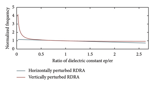
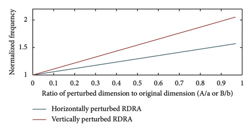
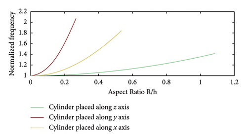
The resonant frequencies of PRDRA calculated using the proposed theory for and modes are in good agreement with simulated and measured frequencies. In [32], the concept of RDRA with rectangular-shaped perturbation is used to achieve a wider impedance bandwidth and higher gain by exciting higher order modes at lower resonant frequencies. This is achieved by maintaining a higher εp/εr ratio. Higher εp/εr ratios lead to lower changes in RDRA and PRDRA resonant frequencies. This is supported by the normalized frequency graph of PRDRA with rectangular-shaped perturbation in Figure 4. When a perturbation is made along the length or width of the RDRA, it is horizontally perturbed, and if it is made along the height, it is vertically perturbed. When a higher dielectric constant material is surrounded by a lower dielectric constant material, more fields will be confined in the higher dielectric constant region, resulting in a shorter distance between two adjacent magnetic dipoles. In [32], the same concept of perturbation is used to generate mode at a lower resonant frequency of 12 GHz. Furthermore, the accuracy of perturbation theory for PRDRA with rectangular-shaped perturbation, excited in the dominant mode, is already verified by authors in [16, 28].
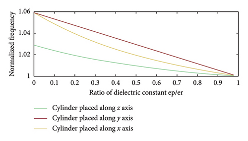
The results of the proposed theory closely match the simulated and fabricated results. PRDRA has a small change in the resonant frequency compared to RDRA due to the minimal εp/εr and radius/height ratios of the cylinder. This can be validated by the normalized frequency graphs shown in Figures 5(a) and 5(b) for RDRA with cylindrical shape perturbations. The reason that both RDRA and PRDRA in [33] resonate at 15 GHz is the same. The concept of perturbation results in reduced effective dielectric constant without much changing the operating frequency of RDRA, and thus, utilized for gain and bandwidth enhancement for 5G applications in [33] by exciting higher order modes in PRDRA.
Tables 3 and 4 show that the position of the perturbation is the same in both cases; one is PRDRA with a rectangular-shaped perturbation with a higher dielectric constant material perturbation, and the other is PRDRA with a cylindrical-shaped perturbation with a lower dielectric constant. In Table 3, the concept of perturbation is used to generate higher order modes at lower resonant frequencies, with a wider bandwidth and higher gain. In Table 4, the concept of perturbation is used to increase antenna gain and bandwidth without significantly affecting the operating frequency of the antenna. As a result, RDRAs with various perturbation shapes can be used to design antennas with higher order modes, wider bandwidth, and higher gain. The proposed theory validated that the shape, dielectric constant, and position of perturbation will be deciding factors for the operational behavior of PRDRA.
| DRA | Mode | ɛr | ɛp | Dimensions (a × b × d)(mm3) | Dimensions of the rectangle (A × B × D) (mm3) | fsim (GHz) | fmeas (GHz) | fprop (GHz) | % Δfsim = (fsim − fprop)/fsim | %Δfmeas = (fmeas − fprop)/fmeas |
|---|---|---|---|---|---|---|---|---|---|---|
| Unperturbed RDRA | 3.5 | — | 20 × 20 × 82 | — | — | — | 11.03 | — | — | |
| 3.5 | — | 20 × 20 × 82 | — | — | — | 12.78 | — | — | ||
| Perturbed RDRA | 3.5 | 10 | 20 × 20 × 82 | 4 × 4 × 80 | 10.67 | 10.70 | 10.34 | 3.09 | 3.36 | |
| 3.5 | 10 | 20 × 20 × 82 | 4 × 4 × 80 | 11.7 | 11.23 | 11.93 | −1.96 | −6.23 | ||
| DRA | Mode | ɛr | ɛp | Dimensions (a × b × d) (mm3) | Radius of the cylinder (r) (mm) | fsim (GHz) | fmeas (GHz) | fprop (GHz) | % Δfsim = (fsim − fprop)/fsim | %Δfmeas = (fmeas − fprop)/fmeas |
|---|---|---|---|---|---|---|---|---|---|---|
| RDRA | 9.8 | — | 3.84 × 3.84 × 38.44 | — | 15 | 14.98 | 14.8 | 1.33 | 1.20 | |
| PRDRA | 9.8 | 1 | 3.84 × 3.84 × 38.44 | 0.4 | 14.9 | 14.9 | 14.893 | 0.04 | 0.04 |
4. Conclusion
Perturbed DRAs operating in higher order modes are used to design antennas with large impedance bandwidth and high gain. The perturbation theory is proposed for higher order modes of RDRAs with rectangular- and cylindrical-shaped perturbations. The proposed theory is verified and validated using simulated and measured results, and it is found to be in good agreement with the published data. A further theory can be used to explain the process of generating higher order modes and increasing bandwidth through perturbation. The combination of dielectric constant, shape, and perturbation position will help in the design of higher order perturbed DRAs. The new theory will bridge the gap between simulated and measured results by providing a precise measure of dimensions for the given design frequency. The theory can be extended for perturbed structures obtained through a combination of different shapes of perturbation.
Conflicts of Interest
The authors declare no conflicts of interest.
Funding
No funding was obtained for this study.
Acknowledgment
The authors have nothing to report.
Open Research
Data Availability Statement
The data that support the findings of this study are available from the corresponding author upon reasonable request.


