Research on Microvibration Transmission of Control Moment Gyro Considering Internal Structural Flexibility
Abstract
Control moment gyro (CMG) can produce microvibration and influence the performance of sensitive instruments aboard the spacecraft. This article is aimed at constructing the microvibration transmission model of a large-scale CMG incorporating the flexibility of its internal structural components and at analyzing the transmission characteristics of microvibration disturbance. The system equation of a single-gimbal CMG is established by assembling motion equation of each component with matrix formulation, where the structural components are modeled as flexible bodies, and the model assuming all structural components as rigid bodies is also derived for comparison. Disturbance transfer function (DTF) is proposed as the tool to characterize the CMG disturbance transmission. The model proposed is validated by the good correlation between the test and simulation results of the modal features and disturbance output of a 1500-Nms CMG. Assuming all components as rigid bodies is verified to induce an unacceptable error, and the internal structural flexibility can significantly affect the CMG dynamic features. With DTFs, the transmission paths of various disturbance inputs are identified, and the mechanism of some gimbal angle–dependent features of the CMG is revealed. The static imbalance of the flywheel is demonstrated to be the decisive factor inducing output at the fundamental harmonic for the CMG tested, and estimation of the disturbance input at the 2Ω harmonic is achieved. The model established and the mechanism clarified of the disturbance transmission offer an important basis for the optimal design of CMG in minimizing its microvibration.
1. Introduction
Control moment gyroscope (CMG) is the actuator of spacecraft attitude control. It can produce large and accurate torque output and exhibits excellent control linearity, antidisturbance, and rapid response features; therefore, CMG is an ideal actuator to achieve attitude change for large and long-life spacecraft, such as Mir, Skylab, ISS, and China Space Station, and also agile satellites. CMG generates the required torque by gimballing the angular momentum vector of a flywheel spinning at a high and constant speed. However, undesirable microvibration is produced and transmitted to the spacecraft simultaneously. The microvibration emitted by CMG can significantly deteriorate the ultraquite environment required by sensitive instruments, making CMG one of the main sources of vibration on a spacecraft [1–5]. The microvibration of CMG is induced by many factors, including the mass imbalance of the flywheel and imperfection and nonlinearity in the bearings [6–8]. The mass imbalance of the flywheel mainly causes microvibration at the fundamental harmonic, which is generally the dominant part in the overall disturbance output, and other factors produce polyharmonic, subharmonic, and broadband components with relatively low amplitude.
Reaction/momentum wheel assemblies (R/MWAs) are actuators also commonly used on spacecraft for attitude control, which provide reaction torque by adjusting the rotational acceleration of the high-speed rotary flywheels. The rotary flywheel storing momentum is the key component of both R/MWAs and CMG and also the primary source of disturbance for both. A large amount of researches have been conducted on the microvibration of R/MWAs, which provides important reference for the study of CMG dynamics. Masterson, Miller, and Grogan [9, 10] developed an analytical model of reaction wheel (RW) incorporating the gyroscope effect of the rotating flywheel. Zhang et al. [11, 12] developed the disturbance model of a cantilever configured flywheel. Peng, Fang, and Cui [13] proposed a dynamical model of a magnetically suspended momentum wheel assembly (MWA). The dynamic coupling problem of a MWA with its support brackets was studied by Narayan, Nair, and Ghosal [14]. Zhang, Aglietti, and Zhou; Zhou, Aglietti, and Zhang; and Zhang, Aglietti, and Ren [15–17] developed the analytical model of a system composed of a cantilevered flywheel and a seismic mass, and an indirect method was proposed to acquire the force at the wheel assembly interface by detecting the accelerations of the seismic mass. With dynamic mass–based coupling method, Addari and Aglietti and Addari, Aglietti, and Remedia [18–20] investigated the disturbance transmission at the interface between coupled RW and its support panel and demonstrated that loads exchanged at the interface are different from those measured when the RW is hard mounted. Xia et al. [21] proposed a disturbance model of a cantilevered MWA reflecting the structural coupling due to insufficient stiffness of MWA and installation foundation, by introducing the amplification coefficient. Some other researchers focused on the identification of the model parameters based on the measured disturbance of R/MWAs [22–24]. The bearing supporting the flywheel is the primary source to introduce nonlinearity, which results in additional excitations in the sub- and high-order harmonics. To capture this effect, many researches were devoted to the incorporation of the interior nonlinear dynamics of the bearing into the system model of R/MWAs. Le et al. [25] developed a disturbance model of RW incorporating the varying compliance of the bearing radial stiffness. Wang et al. [26] proposed a method considering nonlinear bearing restoring forces, which are obtained through an iterative computation procedure performed at each transient time step. Alkomy and Shan [27] introduced a nonlinear model of RW to predict the disturbance produced by the waviness in all bearing parts. Longato et al. [28] proposed a methodology to recreate the microvibration signature due to ball bearing imperfections with finite element (FE) transient simulation.
Compared with R/MWAs, CMG is more complex in structure composition and owns different microvibration characteristics. Through modeling of the microvibration of CMG with Lagrange or Euler method, X. Li, Cheng, and X. Li; X. Li, Cheng, and M. Li; and Li and Cheng [29–31] investigated the microvibration characteristics of CMG and the coupling effects between the CMG and its flexible installation boundary. By establishing an integrated model of CMG and satellite, Y. Zhang and J. Zhang [32] investigated the disturbance of CMG due to mass imbalance on the attitude precision and stabilization of a satellite. Luo, Li, and Jiang [33] established the analytical model of a passive isolation system for CMG clusters and demonstrated the significant effect of the gyroscopic effects of CMG on the system characteristics. Deng, Liu, and Zhao [34] developed a modeling method that combines the dynamic model of the flywheel with the transfer function of the low-speed gimbal acquired by tests. Wu et al. [35] proposed a model of CMG with 18 degrees of freedom (DoF) and implemented model parameter identification with modal tests. Many researchers developed nonlinear microvibration model of CMG by introducing nonlinearity in the bearings. Luo et al. [36] developed the model of a double-end supported CMG incorporating the nonlinear stiffness of both the flywheel and gimbal bearing systems. Wang, Han, and Zhou [37] proposed the model of a cantilevered CMG incorporating the nonlinear bearing supporting forces, which are solved iteratively at all transient instances. This nonlinear time-varying dynamic model was later extended to a double-end supported CMG [38].
Currently, most researches on the microvibration dynamics of the CMG as well as R/MWAs assume as rigid bodies their internal structural components. However, for large-scale CMG commonly used on large spacecraft, such as space station and large space observatory, due to the stringent demand on the weight cost, which tends to reduce the overall structure rigidity, the internal structural flexibility of the CMG becomes effective and may couple with the rocking motion of the spinning flywheel in the relatively low frequency range, which can significantly affect the dynamic behavior of the microvibration in the CMG. Furthermore, current researches on the microvibration of CMG show a lack of characterization of the transmission path in the frequency domain from the input of various disturbances to the different components of the output, and the decisive factors of the overall characteristics of the microvibration transmission in the CMG are not clearly identified either, while these constitute an important basis for the optimal design of CMG when the minimization of the disturbance output is concerned.
In this article is proposed and verified the dynamic modeling of the microvibration transmission of a large-scale double-end supported single-gimbal CMG considering the flexibility of the structural components, based on which the internal transmission mechanism of the disturbance is clarified. In Section 2, the disturbance transmission model of the CMG is established, where the flexibility of the structural components is fully incorporated, and for comparison, the model assuming the structural components as rigid bodies is derived as well. In Section 3, the disturbance transfer function (DTF) is formulated for the convenience of characterizing the disturbance transmission in the CMG. Section 4 presents the measurement set-up and test results of the disturbance output of a CMG. In Section 5, comparison is made between the test and simulated results for model validation. The mechanism of the disturbance transmission in the CMG is analyzed with DTFs, and the accuracy of the model in predicting the disturbance output is verified. Finally, the conclusion is given in Section 6.
2. Microvibration Dynamic Model of CMG
2.1. CMG Description and Model Assumption
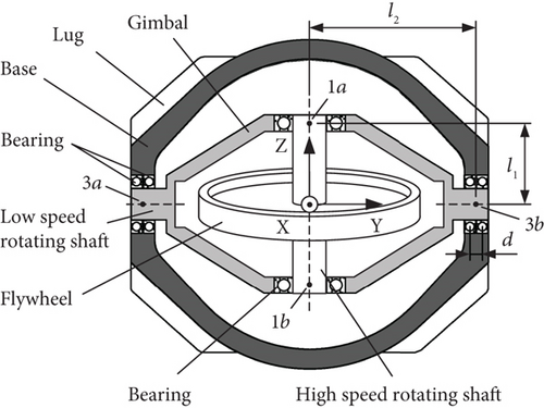
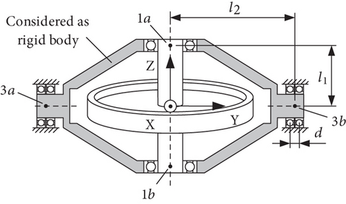
The configuration of a double-end supported single-gimbal CMG is shown in Figure 1. The CMG mainly consists of three parts: the flywheel, the gimbal, and the base. Several internal angular contact ball bearings are used to provide compliant supports for the flywheel and the gimbal, making two rotor-bearing systems formed, as the flywheel-bearing system and the gimbal-bearing system. The flywheel together with the high-speed rotating shaft is supported by a pair of bearings, with one bearing at each end of the shaft. The gimbal is supported by a pair of bearings at both ends of the low-speed rotating shaft as shown in Figure 1; this bearing configuration is aimed at increasing the supporting stiffness of the gimbal-bearing system, considering the relatively large mass of the assembly of the flywheel and the gimbal. Four lugs at the corners of the base provide the installation interface, which output disturbance when the CMG operates.
- 1.
The flywheel together with the high-speed rotating shaft is considered a rigid body with 5 DoF, including 3 translations and 2 rotations about its two orthogonal radial directions;
- 2.
The gimbal and the base are considered flexible bodies;
- 3.
The gyroscopic effect of the gimbal is neglected due to its low rotation speed, which is no more than 10 rpm;
- 4.
Each bearing is modeled as a linear spring with axial and radial stiffness and damping.
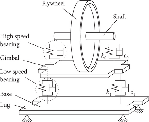
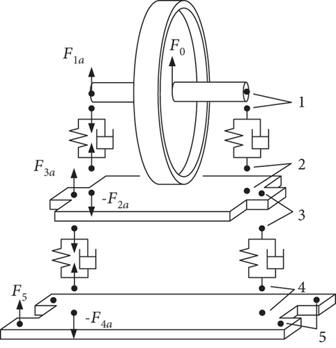
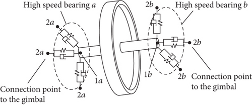
The dynamic model of CMG is illustrated in Figure 2(a). One end of the spring that models the high-speed bearing is at the center of one end of the high-speed shaft, as denoted by Point 1 in Figure 2(b). The other end of the spring denoted by Point 2 in Figure 2(b) lies at the bearing center and is rigidly connected to the gimbal. This modeling of spring and connection is also adopted for the low-speed gimbal-bearing system, with the ends of the spring denoted by Points 3 and 4 in Figure 2(b), and Point 5 denotes the lug of the base. With the modeling and simplification adopted above, the whole CMG can be separated into several parts connected at a number of points, through which disturbance transmits from the flywheel to the lug.
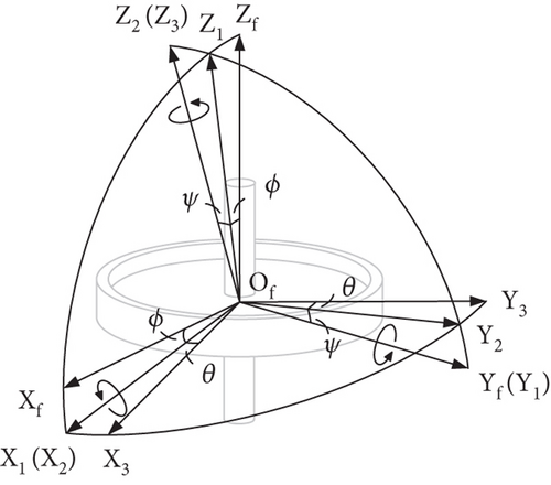
Several coordinate frames are defined for convenience. OXYZ is an inertial frame with the origin at the geometrical center of the installation interface, and the OY axis is parallel to the gimbal axis. All vibration motions of parts of the CMG are referred to this frame. OgXgYgZg is a frame fixed to the gimbal with the origin at its center of mass (CoM); OgXgYgZg is parallel to the inertial frame when the gimbal angle is 90°. OfXfYfZf is the frame of the flywheel with the origin at the CoM of the flywheel and is parallel to OgXgYgZg and rotates with the latter. OfZf is along the spinning axis.
2.2. Motion Equation of the Flywheel
2.3. Equation of the Flywheel-Bearing System
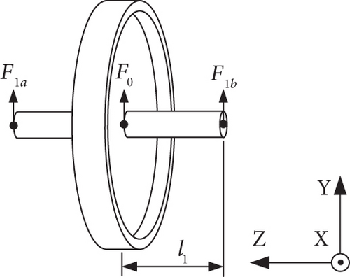
Due to the flexibility of the gimbal, the translational as well as the rotational displacements at the two connection points of the high-speed bearing to the gimbal cannot be described by those of two points on a rigid body. Figure 5 shows the equivalent model of the flywheel-bearing system, where the connection points between the high-speed bearing and the gimbal have “independent” displacements. The vibration of the coupled system of the flywheel-bearing is modeled with 17 DoF, including 5 DoFs of the flywheel and 6 DoFs at each connection point of the two bearings to the gimbal. In order to facilitate the assembling of the CMG system equation in the subsequent section, the equation of motion (EoM) of the flywheel-bearing system is derived through matrix formulation.
2.4. System Equation of CMG
Equation (25) is derived for the gimbal angle of 90°; when the assembly of gimbal and flywheel rotates about the OY axis, elements related to the flywheel and gimbal need to be reformed through coordinate rotation, while elements related to the base keep unchanged.
2.5. Equation of CMG With Rigid Body Assumption
The flexibility of the gimbal and base obviously can complicate the dynamic behavior of the CMG system; in order to help clarify the dynamic characteristics of the CMG and effects due to the introduction of structural flexibility, the dynamic model of the CMG considering the gimbal and base as rigid bodies is derived.
These equations imply that the overall translational motion of the system is decoupled from its overall rotational motion, the rotational motion of the gimbal about OgZg axis is decoupled from rotation in other directions, and the three translational motions are decoupled from each other. This is the result of modeling the bearing as a spring with axial and radial stiffness and considering no crosscoupling between stiffness in different directions. Equation (37) indicates that the gyroscopic effect of the flywheel can influence the rotations of the gimbal through motion coupling expect for the rotation of the gimbal about OgZg; thus, the natural frequencies corresponding to the other four rotation DoFs of the system change with the spinning speed of the flywheel. Equation (38) indicates that the natural frequencies relative to the translational motion are not affected by the gyroscopic effect of the spinning flywheel.
3. DTF
3.1. Disturbance Input
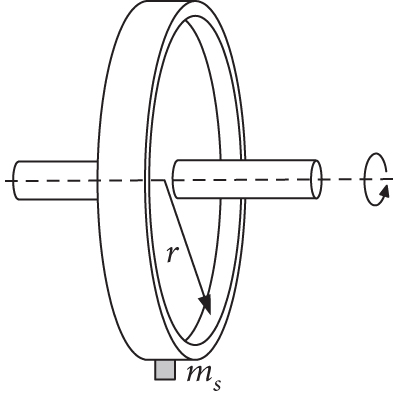
Disturbance input to the CMG is caused by many factors, including the mass imbalance of the flywheel, irregularity in the bearings, and nonlinearity in the bearing stiffness. Static imbalance arises due to the deviation of the CoM of the flywheel from its geometric center, and dynamic imbalance is caused by the angular misalignment of the principal axis of the flywheel and the spin axis, as shown in Figure 7. The static and dynamic imbalances, respectively, produce a centrifugal force and a torque in the radial direction rotating with the same speed as the flywheel, which are considered the main contributor to the overall disturbance output of CMG. Factors other than the mass imbalance, such as the bearing irregularity and nonlinearity, mainly induce tonal disturbance input of sub- and high orders of harmonics, which contribute less to the overall disturbance output compared with the mass imbalance.
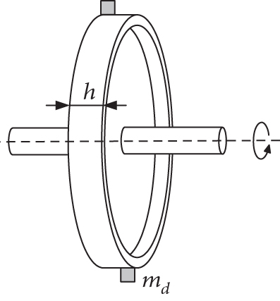
Note that the disturbance input of torque about the spin axis is neglected in the analysis.
3.2. Disturbance Output
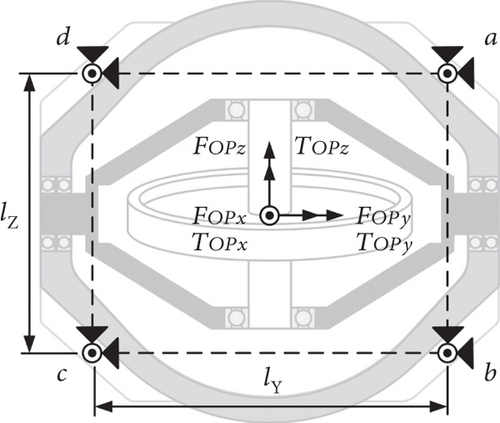
3.3. Transfer Function
4. Microvibration Disturbance Test and Results
4.1. Test Set-Up
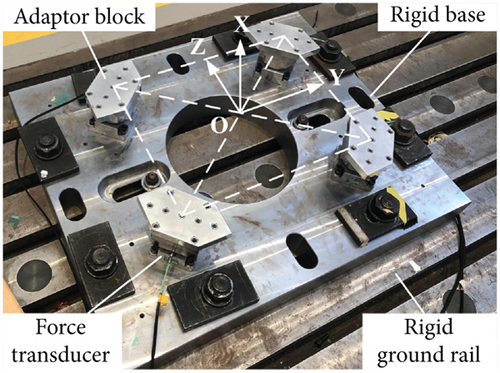
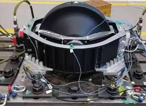
A 1500-Nms CMG with a weight of 128 kg is measured for the disturbance output. The parameters of the CMG are shown in Table 1. Due to the heavy weight of the CMG, a measurement platform as shown in Figure 9(a) is designed for the disturbance measurement. The platform is assembled with one rigid base, four adaptor blocks, and four Kistler 9377C force transducers. Each transducer measures the three components of the disturbance force output at one lug of the CMG. The adaptor block is used to connect the CMG lug to the force transducer, and the assembly of transducer and adaptor block is installed on the rigid base, which is fixed to the ground rail. Accelerometers are attached to each assembly of transducer and adaptor block, and the natural frequency is acquired through hammering method. The frequency of the first bending mode of each assembly of transducer and adaptor block is larger than 1500 Hz, indicating the high rigidity of the platform. The CMG is connected to the platform through the lugs, as shown in Figure 9(b).
| Parameters | Notation | Value |
|---|---|---|
| Mass | Total mass | 128 kg |
| Flywheel, mf | 49 kg | |
| Gimbal, mg | 31 kg | |
| Flywheel spinning speed | Ω | 7000 rpm |
| Inertia of flywheel | Radial, Ir | 1.13 kg·m2 |
| Polar, Ip | 2.16 kg·m2 | |
| Mass imbalance of flywheel | Static, Us | 7.2 × 10⁻⁶ kg·m |
| Dynamic, Ud | 2.8 × 10⁻⁷ kg·m2 | |
| Inertia of gimbal | About OgXg, Igx | 1.25 kg·m2 |
| About OgYg, Igy | 0.90 kg·m2 | |
| About OgZg, Igz | 0.77 kg·m2 | |
| Half span of high-speed bearings | l1 | 0.17 m |
| Half span of low-speed bearings | l2 | 0.32 m |
| Distance between two adjacent low-speed bearings | d | 0.027 m |
| Distance between lugs of CMG | Along the OY axis, lY | 0.58 m |
| Along the OZ axis, lZ | 0.43 m | |
| Stiffness of high-speed bearing | Radial, kr01 | 5.54 × 10⁷ N/m |
| Radial, kr02 | 4.73 × 10⁷ N/m | |
| Axial, ka0 | 2.13 × 10⁷ N/m | |
| Stiffness of low-speed bearing | Radial, kr11 | 5.51 × 10⁷ N/m |
| Radial, kr12 | 4.69 × 10⁷ N/m | |
| Axial, ka1 | 2.46 × 10⁷ N/m | |
4.2. Disturbance Output
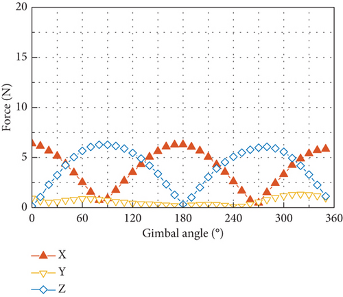
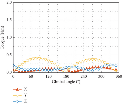
The force output at the four lugs of the CMG is measured when the CMG is operating at a series of gimbal angles from 0° to 350° with an interval of 10° and with the flywheel spinning at a constant speed of 7000 rpm. Datasets are obtained when the gimbal keeps stationary at 36 angles, aimed at making the microvibration of the spinning flywheel the only disturbance source. The total disturbance output at the installation interface is obtained with the 12 force components measured and by using Equation (44). Figure 10 displays the six components of the disturbance output in the frequency domain. It is shown that each component of the disturbance output consists of a series of spikes at different harmonics, and their amplitudes generally change with the gimbal angle. The fundamental harmonic is the dominant part in the overall output, while the 2Ω harmonic has less but considerable contribution.
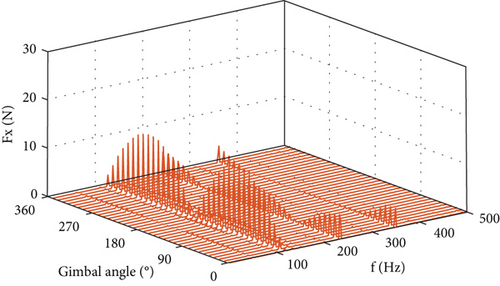
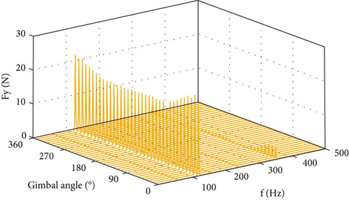
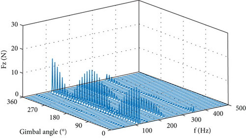
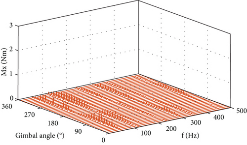
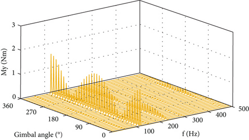
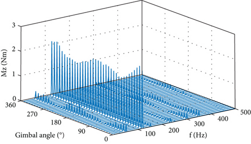
Figure 11 plots the six components of the output at the spike of 116.7 Hz, which is at the fundamental harmonic. Forces in the OX and OZ axes and torques in the OX and OY axes exhibit as trigonometric function of the gimbal angle with 0 or π/2 phase difference. Force in the OY axis is larger than the maximum in the other two directions, and so does the torque in the OZ axis.
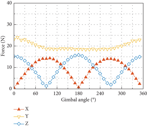
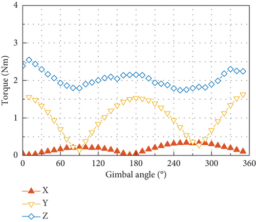
Figure 12 plots the six components of the output at the spike of 233.3 Hz at the 2Ω harmonic. Forces in the OX and OZ axes and torques in the OY axis, respectively, exhibit the variation with the gimbal angle as those at the fundamental harmonic by a phase difference of π/2, and force in the OY axis and torques in the OX and OZ axes are small.
5. Simulation and Verification
5.1. Modal Frequency and Shape
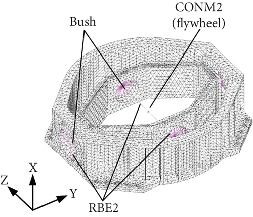
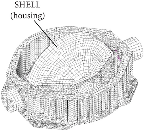
A FE model of the microvibration transmission system of CMG is established using software MSC Patran/Nastran, as shown in Figure 13. The flywheel is modeled using a concentrated mass element CONM2 positioned at its CoM. The bodies of the gimbal and the base are discretized using tetrahedron elements. Four BUSH elements are used to model the two high-speed bearings and two pairs of low-speed bearings. Connection between different parts of the CMG is modeled with the RBE2 elements. The housing of the flywheel is also included in the model to reflect its stiffening effect on the gimbal structure, which is discretized using SHELL elements. When the flywheel is spinning, the gyroscopic effect is added with the RGYRO card.
Modal frequencies of the CMG with the flywheel still and at the gimbal angle of 90° are calculated using the FE model. The simulated results with the FE model and those acquired with hammering test are listed at the left side in Table 2, where good correlation is shown between the two groups of results. The reason for none identification of the first mode in the test is that the hammering points are all placed on the base to avoid potential damage to the flywheel, gimbal, and bearings. The missing of the second mode in the test is due to none attachment of accelerometer on the flywheel. The two missing modes above 350 Hz may be attributed to the proximity of the related frequencies.
| Test | Model simulation | ||
|---|---|---|---|
| Flexural gimbal and base | Rigid | ||
| /Hz | /Hz | Mode shape description | /Hz |
| — | 22.8 | Rocking mode of flywheel and gimbal about the OY axis | 22.8 |
| — | 123.5 | Translational mode of flywheel along the OZ axis | 132.8 |
| 131.9 | 132.4 | Coupled translational mode of flywheel and gimbal along the OY axis | 145.9 |
| 139.1 | 138.5 | Translational mode of flywheel coupled with translational and bending mode of gimbal along the OX axis | 188.0 |
| 198.0 | 198.9 | Rocking mode of flywheel about the OX axis coupled with flexural mode of gimbal | 225.4 |
| 350.9 | 358.9 | Translational mode of flywheel and opposed translational mode of gimbal along the OZ axis | 436.7 |
| — | 382.1 | Translational mode of flywheel and opposed translational mode of gimbal along the OY axis coupled with flexural breathing mode of base | 428.6 |
| — | 383.7 | Rocking mode of flywheel coupled with opposed rocking mode of gimbal about the OY axis | 395.9 |
| 384.8 | 391.6 | Flexural breathing mode of base | — |
The natural frequencies of the model adopting assumption of rigid gimbal and base are obtained by solving the characteristic equations of Equations (37) and (38) and listed at the rightmost column in Table 2. Significant discrepancies exist between the simulation and test results, where the model prediction exceeds the test results to a large degree. This implies that the simplification of the gimbal and base of CMG as rigid body is not appropriate and can lead to unacceptable error in the model prediction for large-scale CMG.
The effects of the structural flexibility on the CMG dynamics can be distinctly reflected by the mode shape obtained with the FE model considering a still flywheel. The mode shape of the CMG at 138.5 Hz is shown in Figure 14(a), where evident bending deformation of the gimbal in the OX direction appears. The mode shape at 198.9 Hz is shown in Figure 14(b), where the gimbal exhibits remarkable flexural deformation in the YZ plane.


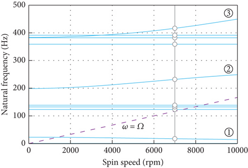
The Campbell diagram calculated with the FE model is depicted in Figure 15, where the variation of natural frequency of the CMG with the spinning speed of the flywheel is depicted. There exist one backward whirling curve and two forward whirling curves below 500 Hz, which are numbered in Figure 15. As the flywheel spins from 0 to 7000 rpm, frequency of the backward whirling mode decreases by 5.4 Hz, while frequencies of the two forward whirling modes increase by 33.1 and 32.5 Hz. The small decrease in the frequency of the backward whirling mode reflects the small effect of the gyroscopic term on the rocking mode of flywheel and gimbal about the OY axis. Natural frequencies of the translational modes keep constant as the spinning speed increases, indicating its decoupling with the rocking of the spinning flywheel.
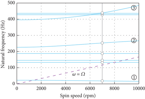
The Campbell diagram from the model with rigid body assumption is depicted in Figure 16. Though the natural frequencies are different from those in Figure 15, the decoupling between the rotational and translational modes is reflected by the two kinds of models, which coincides with the theoretical prediction in Section 2.5. This implies that the flexibility of the gimbal and base mainly introduces local flexural modes and accordingly reduces the natural frequencies compared with the case adopting rigid body assumption. However, the introduced flexibility has little effect on the overall dynamic feature of the CMG that the rotational modes are decoupled from the translational ones.
5.2. DTF
Figure 17 depicts the DTFs at the gimbal angle of 90° and with the flywheel spinning at 7000 rpm, which are obtained with the FE model by exerting, respectively, radial force, axial force, and radial torque with unit amplitude at the flywheel center. In Figure 17, the disturbance transfer characteristics of the CMG are clearly revealed. Each kind of disturbance input results in the disturbance output including six components through the dynamic transmission in the CMG. When the flywheel is disturbed radially by force, the output of force is dominated by components in OX and OY directions, and torque output lower by an order of magnitude along OZ can be produced. When the flywheel is disturbed by the axial force, large output of force in the same direction can be produced, and torque output along OY is formed due to the vertical distance between flywheel center and the installation interface. The input of radial torque is efficient in producing output of torque about OX, while can produce little output of force.
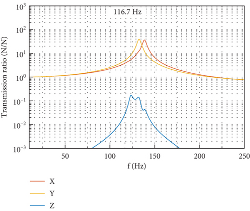
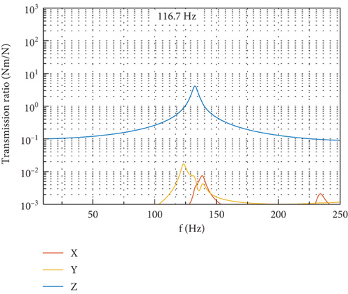
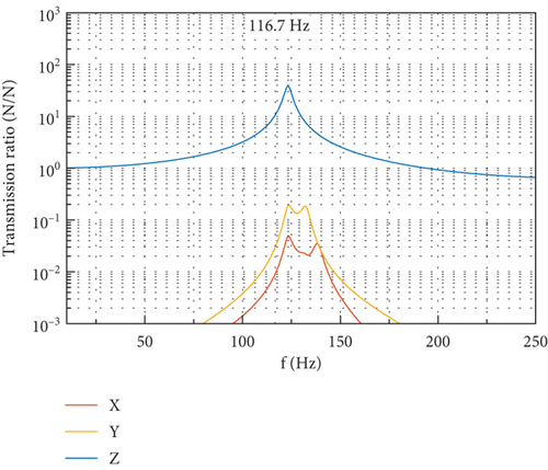
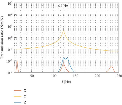
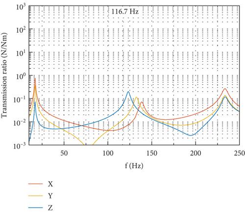
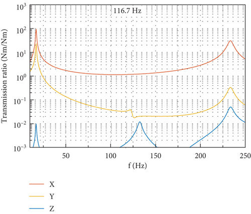
At the fundamental harmonic of 116.7 Hz, there exists evident dynamic amplification in the DTF due to the proximity of the fundamental harmonic to the frequencies of the first few translational modes of the CMG. This implies that, to reduce the disturbance output at the fundamental harmonic, an effective method is to rigidify the whole CMG system to keep a favorable distance between the fundamental harmonic and the frequencies of translational modes along the OX and OY directions.
The spectra of the six components of output measured at the gimbal angle of 90° are shown in Figure 18. For the spectra of force output as shown in Figure 18(a), a peak around 133 Hz on the DTF in the OY direction and another peak around 139 Hz on the DTF in the OX direction can be identified. The appearance of these two peaks is due to the excitation of random noise disturbance input accompanying the tonal ones. If the spikes are removed from the spectra, the remaining part coincides well with the DTFs in OX and OY directions in Figure 17(a). For the spectra of torque output as shown in Figure 18(b), there exists a sharp peak around 18 Hz, which corresponds to the first rocking mode in Table 2 with frequency decrease shown in Figure 15 when the flywheel spins at 7000 rpm, and the shape of spectra near this peak coincides well with the DTFs in Figure 17(f). It is implied from the above that the broadband part of the disturbance output spectra provides a good reference for the identification of some natural frequencies when the flywheel is spinning and the validation of the predicted disturbance transmission as well.
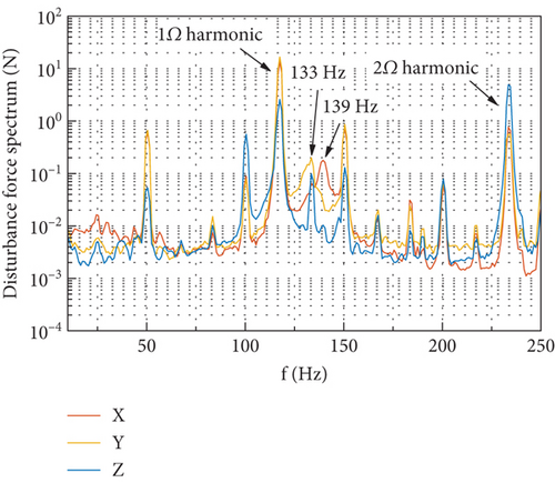
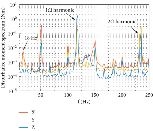
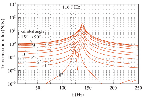
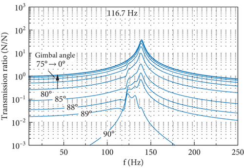
Figure 19 depicts the DTF of the output forces in the OX and OZ axes due to the radial force input as the gimbal angle changes from 0° to 90°. The DTF of the OY force output keeps the same as shown in Figure 17(a) at any gimbal angle and thus is not presented. It is shown that the gimbal angle has a significant effect on the DTF of forces in the OX and OZ axes. When the gimbal rotates from 0° to 90°, the DTF of the force output in the OX axis changes from its minimum to the maximum, while the DTF of the force output in the OZ axis exhibits the reverse trend of variation. This gimbal angle related variation of the DTF is mainly caused by the rotation of the component of the radial force input along the OfXf axis. As the gimbal rotates from 0° to 90°, the two projections of this component of radial force on the OX and OZ axes vary between their minimum and maximum. The component of the radial force input in the OfYf axis always coincides with the OY axis; thus, the DTF of force in the OY axis does not change with the gimbal angle. It is also illustrated in Figure 19 that the shape of the DTF curve is affected by the gimbal angle, especially near the angle where the DTF reaches its minimum. This demonstrates the effect of the gimbal angle on the disturbance transmission by altering the overall stiffness of the CMG.
5.3. Disturbance Output at Fundamental Harmonic
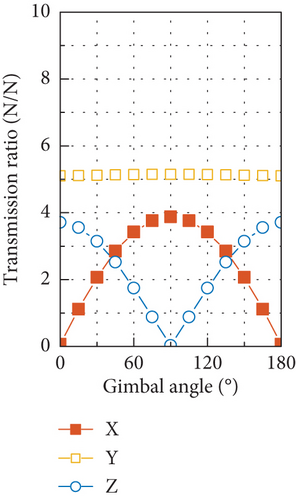
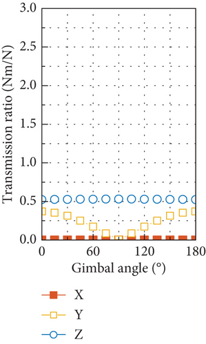
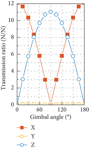
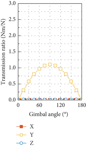
Through simulating the DTFs with the FE model at varying gimbal angles from 0° to 180° with an interval of 15°, the gimbal angle–dependent transmission ratio at the fundamental harmonic is obtained and shown in Figure 20. Some components of the disturbance output exhibit as trigonometric functions of gimbal angle with phases of 0 or π/2, while the rest nearly keeps constant, indicating their independence of the gimbal angle. The largest force output is induced by the axial force input, which is the result of dynamic amplification by the proximity of the fundamental harmonic to the natural frequency of the translational mode along the OZ axis, and the specific case for the gimbal angle of 90° is shown in Figure 17(c). However, at the fundamental harmonic, no axial force input can be caused by the mass imbalance, and zero axial force is adopted in the simulation of disturbance output.
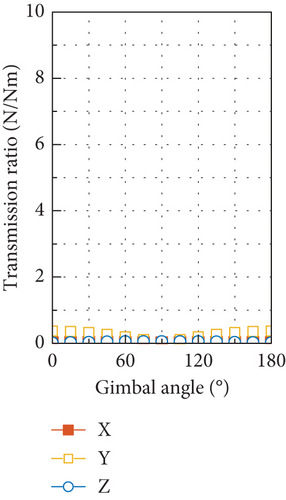
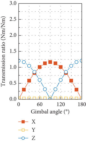
The simulated results of the disturbance output of the tested CMG at the fundamental harmonic are depicted in Figure 21. The radial force input of 3.86 N and radial torque input of 0.15 Nm are used in the simulation, which are calculated with the measured mass imbalance of the flywheel and by using Equation (39), and zero phases are assumed for these two disturbances. Good overall correlation is exhibited between the simulated results and the measured ones shown in Figure 11, with respect to both the amplitudes of the six components of the disturbance output and their variation with gimbal angle.
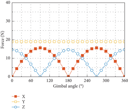
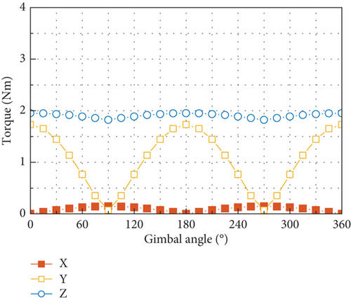
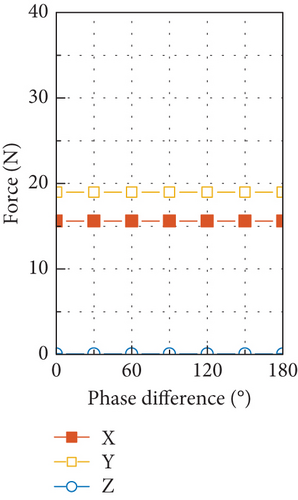
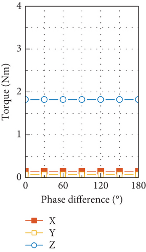
For the tested CMG, the radial force input is an order of magnitude larger than the radial torque input in amplitude. Such a big difference makes the static mass imbalance of the flywheel the dominant factor in producing disturbance output of forces and torques at the fundamental harmonic. If the transmission ratio displayed in Figures 20(a) and 20(b) is multiplied by the radial force input of 3.86 N, the resultant output is very close to the forces and torques shown in Figure 21, and due to the small radial torque input caused by the dynamic mass imbalance, it has negligible contribution to the force output and much less contribution to the torque output compared with the radial force input. Moreover, the dramatic discrepancy in amplitude between the radial force and torque input makes the phase difference between them have little effect on the disturbance output as demonstrated by Figure 22, which is obtained by considering a series of phase differences between the radial force and torque input.
Another obvious feature of the disturbance force output in Figure 21(a) and Figure 11(a) is that the force in the OY axis is larger than the maximum of the other two components. This is because the natural frequency of the first translational mode along the OY axis is smaller than that of the translational mode along the OX axis at the gimbal angle of 90°. Under this situation and by referring to Figures 17(a) and 19, it can be found that the DTFs of force in the OX and OZ directions at the fundamental harmonic are always beneath that in the OY direction. If another combination of stiffness of the high-speed and low-speed bearings is used to make the peak frequency along the OY axis in Figure 17(a) higher than that along the OX axis, the resultant disturbance force in the OY direction as shown in Figure 21(a) will fall below the maximum of the forces in other two directions.
5.4. Estimation of Input at 2Ω Harmonic
Disturbance input at the 2Ω harmonic is induced by factors other than the mass imbalance. Its type and amplitude cannot be analytically determined as those at the fundamental harmonic. However, based on the DTFs predicted and the disturbance output measured at the 2Ω harmonic, an estimation of the disturbance input at the 2Ω harmonic, including its type and amplitude, can be made.
The gimbal angle–dependent transmission ratio at the 2Ω harmonic is shown in Figure 23. Due to the close proximity of the modal frequency related to the rocking motion of flywheel to the 2Ω harmonic, a large disturbance output can be induced by the radial torque input, as shown in Figures 23(e) and 23(f). However, by comparing the test results of the disturbance output at the 2Ω harmonic in Figure 12 with the transmission ratio shown in Figure 23, it is found that the variation of the test results with gimbal angle conforms to that of output by axial force input as shown in Figures 23(c) and 23(d). This implies that the 2Ω harmonic disturbance output of the CMG tested is most likely to be produced by the axial force input and that there exists little input of radial torque as well as radial force at this frequency.
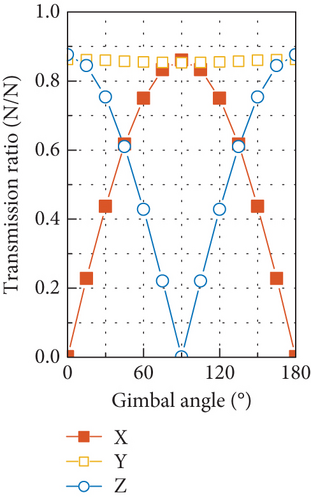
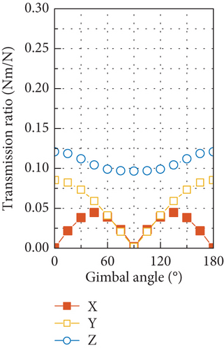
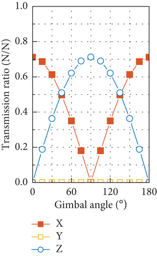
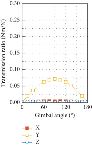
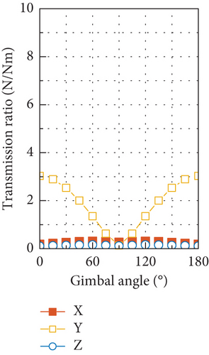
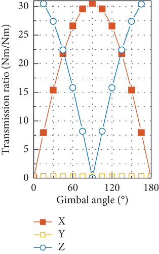
Through comparing the transmission ratio of the force output in Figure 23(c) with the amplitude of output of force shown in Figure 12(a), an amplitude of 8.8 N can be estimated for the axial force input at the 2Ω harmonic. With this estimated amplitude of the axial force and by utilizing the transmission ratio in Figure 23(d), the output torque in the OY axis with a maximum of 0.63 Nm can be predicted, which is close to the test result of 0.42 Nm in Figure 12(b).
6. Conclusion
The dynamic transmission model of a large-scale CMG is established with the combined use of Lagrange method and FE method, where the flexibility of the internal structural components of the CMG is fully incorporated. The analytical model of the CMG assuming all structural components as rigid bodies is also established for comparison. The DTF is introduced and formulated based on describing the disturbance input in a general matrix form, which reflects the transmission ratio in the frequency domain from the input on the flywheel to the output at the CMG installation interface.
The disturbance output of a 1500-Nms CMG is measured with a newly designed platform, and modal survey is performed. Good correlation is shown between the modal features from the tests and those of the FE model simulation. The decouple of the translational modes from the rotational ones is reflected by the FE model, which coincides with the theoretical prediction of the model with rigid body assumption, but the latter overestimates the natural frequency, leading to an unacceptable error. The introduced structural flexibility is mainly to cause local flexural modes, which affect the transmission characteristics of CMG by reducing the natural frequency.
The output predicted at the fundamental harmonic correlates well with the test results with respect to both the amplitude and variation with the gimbal angle, which validates the model proposed. Through analysis on the DTFs, the effective transmission paths of different disturbance input are identified, and mechanism of some typical gimbal angle–dependent features of the disturbance output is revealed. For the CMG tested, the static imbalance of the flywheel is the primary source of inducing the output of both forces and torques, and the effect of phase difference between the static and dynamic imbalances is negligible. With the DTFs, the axial force is estimated as the main source of input at the 2Ω harmonic and its amplitude is predicted accordingly.
Conflicts of Interest
The authors declare no conflicts of interest.
Funding
No funds were received.
Appendix A
, , and denote the position of the interface point of the lug.
Open Research
Data Availability Statement
The authors’ institution has a proprietary right to all data and models presented in the paper. Providing data and models is not allowed without permission from the author’s institution.


