Predetermined Performance Control of Spacecraft Formation Based on SE(3) Error Description
Abstract
For the obstacle avoidance and formation maintenance issues of spacecraft formation, a control method with prescribed performance is proposed. Firstly, an error description system based on SE (3) is established. Secondly, to simplify the control system, collision avoidance, formation control of leading spacecraft, and containment control of following spacecraft are combined. Finally, the control errors are kept within the prescribed performance function range using prescribed performance control. Simulation results of spacecraft formation completing complex tasks under external disturbances validate the effectiveness of the proposed control scheme.
1. Introduction
With the development of modern science and space technology, people’s demand for space exploration has also increased. Spacecraft formation is an essential tool for space missions and plays an essential role in spacecraft rendezvous and docking, asteroid companion flight, in-orbit satellite maintenance, and space debris management [1–3]. However, as space missions become increasingly complex and diverse, the technical requirements for spacecraft formations are becoming more demanding. The attitude and orbit control of spacecraft and collision avoidance within spacecraft formations have received significant attention as the core technology for the formation to complete the mission in orbit.
Modeling spacecraft is the basis of controller design. Spacecraft attitude trajectory integration modeling methods, which consider the coupling of spacecraft attitude motion and positional motion, effectively improve the accuracy and response speed of spacecraft control and have received widespread attention. Most current modeling methods that consider spacecraft attitude trajectory integration are based on dual quaternions [4, 5]. The six-degree-of-freedom (6DOF) motion of the next spacecraft is simulated in [4] using dyadic quaternions, accounting the coupling between spacecraft position and attitude. An artificial potential function based on dyadic quaternions is proposed in [5] to address the problem of integrated position and attitude control during autonomous spacecraft rendezvous and docking.
However, these methods have the disadvantages of ambiguity and rewinding, which, in practice, reduce the response time of the spacecraft and lead to higher energy consumption. SE (3), as a new modeling method that avoids the issues of ambiguity, singularity, and receding winding that arise in the description of rigid body attitudes, is also widely used in the field of attitude orbit integration control and modeling of spacecraft [6–8]. A robust adaptive controller based on SE (3) with integrated extended state observer (ESO) is proposed in [6], which addresses the tracking maneuvers of coupled spacecraft under model uncertainty and external disturbances. In [7], an adaptive terminal sliding mode controller with SE (3) modeling is proposed to improve the spacecraft docking accuracy. In [8], the relative error dynamics equations for attitude and orbit between two spacecraft under SE (3) modeling are developed for the parameter uncertainty of the spacecraft model. In addition to the above error description systems, which are mostly based on the exponential coordinates of SE (3), there is also an error description system based on the bit-shaped error function obtained on SE (3). In [9], a new construction error function based on SE (3) is designed, and a controller based on this function developed to ensure that the rigid body remains stable with a bounded construction error for a fixed period. Based on SE (3), a more diverse error description system can be obtained, which allows greater flexibility in the design of spacecraft formation controllers.
When spacecraft formations are on space missions, one of the most important tasks is to avoid collisions between spacecraft. However, none of the previously mentioned literature addresses collision avoidance. However, there are some studies that focus on this issue [10–12]. In [10], a decentralized collision avoidance vehicle formation flight tracking control scheme using virtual leading state trajectories is proposed based on SE (3). Lee et al. [11] investigated the finite-time stabilization problem of dispersed collision avoidance in spacecraft formation flight, combining dispersed collision avoidance with finite-time control to achieve convergence of spacecraft motion to the desired state trajectory in finite time while achieving collision avoidance. In the process of solving collision avoidance, the above method does not consider the simultaneous constraints of formation, collision avoidance, and containment and thus cannot address other difficulties encountered during the formation process, which poses challenges in practical applications.
There has been some research on the optimization of control schemes. In [13], a unified control scheme is designed to achieve both formation control and suppression control, and an adaptive robust constraint is proposed to address collision avoidance constraints, formation constraints, and suppression constraints for the satellite. Compared with designing two independent control schemes, this unified approach is more concise and more feasible to solve practical problems. In order to simplify the control scheme and increase its feasibility for solving practical problems, this paper establishes a unified control scheme that transforms the three desired objectives—formation containment, leader, and follower—into a set of servo constraints.
In addition, to achieve collision avoidance and formation maintenance, this paper uses prescribed performance controls to constrain the following errors to a consistent and ultimately bounded level. The spacecraft studied in this paper is highly nonlinear and has a model that has uncertainties and dynamic coupling. In any dynamic system, the presence of uncertainty impacts the performance of the system. Therefore, a control method which is significantly robust to modeling uncertainties and external disturbances is required. Much research has been conducted on control methods modeled using SE (3). In [14], in order to solve the problem of spacecraft orbit maneuvering coupling under uncertain parameters and external interference, an adaptive fixed-time sliding mode control law is proposed. In [15], for the virtual structure control problem of multiagent systems, a formation adaptive super-twisting sliding mode controller is proposed. In [16], an integrated guidance and feedback control scheme was designed. However, the tracking of predetermined steady-state and transient indices is lacking in the literature cited above. These specifications, which are crucial for spacecraft, ensure safety and time constraints.
In [17], an improved prescribed performance control scheme is proposed to achieve prescribed performance trajectory tracking for three-degree-of-freedom UAVs. To this end, this paper applies an improved prescribed performance control protocol to assist in the completion of multiple tasks in spacecraft formation. The control design does not rely on the accuracy of the system model. One of the key features makes it possible to track time-varying trajectories with a degree of accuracy that can be prespecified for both the transient and steady-state responses of the system.
- 1.
The formation configuration error modeling of formation configuration error is performed on the Riemannian manifold SE (3) that is applied, which avoids the singularity and the unwinding phenomenon.
- 2.
Collision avoidance, formation control of leading spacecraft, and containment control of following spacecraft are combined into a new simplified control method. Furthermore, the consistency constraint of formation–containment error is addressed using a prescribed performance function.
- 3.
A prescribed performance controller for spacecraft is proposed to handle model uncertainties and ensure that the performance of the spacecraft formation is within the prescribed limits when completing multiple missions.
2. Problem Statement
2.1. Spacecraft Dynamic Model
Remark 1. SO(3) is the modeling space for spacecraft attitude, and the elements are represented as R ∈ SO(3). ℝ3 is the modeling space of spacecraft position, and the elements are represented as p ∈ ℝ3. The set of elements on SO(3) can be characterized as SO(3) = {R ∈ ℝ3×3|RTR = I, det[R] = 1.
Remark 2. The map [∙]∧ : ℝ3⟶so(3) represents the skew–symmetric matrix operation. The corresponding Lie algebras of Lie group SE (3) are se(3) = so(3) × ℝ3. The map [∙]− : ℝ6⟶se(3) is a bijection map, where se(3) is a Lie algebra of a special Euclidean group and so(3) is a Lie algebra of the three-dimensional special orthogonal group.
2.2. Error Design on SE (3)
SE (3) is a nonlinear space with 16 elements and 10 constraints, but the input in this paper contains only 6 elements. This makes the controller based on SE (3) redundant. Therefore, according to [9, 18], the configuration error function is applied to address this problem.
2.3. Formation–Containment Design
In this paper, the spacecraft formation system consists of N spacecraft, which include K leader spacecraft and N − K follower spacecraft. N = {1, 2, ⋯, N} is the total sequence number set of spacecrafts; L≔{1, 2, ⋯, K} and H≔{K + 1, K + 2, ⋯, N} are the leader and follower spacecrafts, respectively.
In this paper, collision avoidance constraints, formation constraints, and containment constraints are used to obtain that the leader spacecrafts form the desired formation. Meanwhile, the follower spacecraft must enter the formation space defined by the leader spacecraft.
Based on Reference [13], the first leader spacecraft performs trajectory tracking, and the remaining spacecraft form a formation relative to the position of the first leader spacecraft. Consequently, there are variations in the formation constraints and collision avoidance constraints. Formation constraints are redefined, and the permutations and combinations of collision avoidance constraints are adjusted. Some results can be obtained as follows.
Definition 1. It can be obtained from Reference [13], for any initial states pj(t0) and ps(t0), there exists a time Tj < ∞ such that
Moreover, ςjk > 0 and ςjk > 0 are the arbitrarily small positive constants and there exist t⩾Tj, k ∈ L, j ≠ k, s ∈ H.
If Sih(t0) > 0, the spacecraft can avoid collisions with each other. If Sih(t) > 0, h ∈ N, i ≠ h, the spacecraft will avoid collisions.
Make
Then, the formation constraint is described as
Collision–avoidance constraint is described as
The containment constraint is described as where .
In order to simplify the control design, a unified statement of the constraints on each spacecraft is required i, i ≠ 1. Make
Then, the constraint on each spacecraft i, i ≠ 1 can be described as
The constraint-following error is defined as
2.4. Prescribed Performance Control
It is necessary to choose the constant ρ0, which requires the condition ρ0 > |e(0)| to be satisfied and dictates the rate of decrease of ρ(t). In addition, λ is designed to ensure that the convergence rate of e(t) has a lower bound. Furthermore, the parameter represents the steady-state maximum allowable error value. Therefore, choosing a suitable performance function ρ(t) can make the tracking error e(t) have certain steady-state or transient performance characteristics.
Due to the properties of the transformation described above, it can be shown that ensuring the boundedness of ε(t) is sufficient to achieve prescribed performance.
3. Control Design
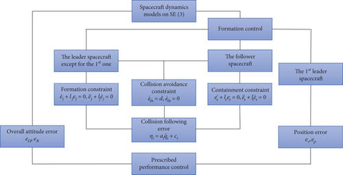
In this section, the design process of the controller is introduced, as shown in Figure 1.
3.1. Overall Attitude Controller Design
Theorem 1. Aiming at the SE (3) model mentioned in Section 2, if the overall attitude control law is used, the sliding surface in Formula (24) exists and it ensures that the angle and angular velocity of the system always remain within a small neighborhood of the sliding surface; specifically, for any t⩾0, there always exists |sq| ⩽ |ρq|. Meanwhile, the system error er and eω can converge in finite time with the prescribed performance.
Proof 1. Design the Lyapunov candidate function as
Taking the derivative of both sides of (30) yields
According to Formulae (22) and (28), Formula (31) can be rewritten as
Substituting (29) into (32) yields
Furthermore, by using the mean value theorem for the term tanh(εq), there exist , where . Then, , which means
Based on Formulae (33) and (34), we can get
Moreover, by using can be transformed into
Then, based on Reference [17], the existence of positive and finite constants and can be proved, and for all implies from (32) that
Therefore, there always exists |sq| ⩽ |ρq| for any t⩾0.
3.2. Position Controller Design of the First Leader Spacecraft
where n is a constant.
Theorem 2. Aiming at the SE (3) model mentioned in Section 2, if the overall attitude control law is used, the sliding surface in Formula (39) exists and it can ensure the input and the position of the system always slides near a small region of the sliding surface; namely, for any t⩾0, there always exists |sl| ⩽ |ρl|. Meanwhile, the signal of the closed-loop system can be ensured to be bounded. The system error ep and eV can converge in finite time with the prescribed performance.
Proof 2. Design the Lyapunov candidate function as
According to Formulae (22) and (39), Formula (46) can be rewritten as
Substituting (44) into (47) yields
Furthermore, according to the mean value theorem for the term sinh(εq), there exist , which implies
According to Formulae (48) and (49), we can get
Furthermore, by using can become
Then, by invoking [17], the existence of positive and finite constants can be obtained, , such that and for all t ∈ [0, τmax). Hence, (47) can be rewritten as
Therefore, there always exists |sl| ⩽ |ρl| for any t⩾0.
3.3. Formation Controller Design
Theorem 3. Aiming at the SE (3) model mentioned in Section 2, if the formation–containment control law is applied, the constraint-following error in Formula (54) exists and it can ensure the system state always slides near a small area of the sliding surface; namely, for any t⩾0, there will always |ηi| ⩽ |ρi|. Meanwhile, the signal of the closed-loop system can be ensured to be bounded. The formation of the spacecraft will satisfy the conditions for collision avoidance, formation maintenance, and containment constraints.
Proof 3. Design the Lyapunov candidate function as
It can be calculated from (58) that
According to Formulae (22) and (54), Formula (59) can be rewritten as
Substituting (57) into (60) yields
Furthermore, by using the mean value theorem for the term sinh(εq), there exist , where , such that which implies
According to Formulae (61) and (62), we can get
Furthermore, by using can become
Then, based on Reference [17], the existence of positive and finite constants can be obtained, , such that and for all t ∈ [0, τmax). Hence, it can be rewritten as
Therefore, there always exists |ηi| ⩽ |ρi| for any t⩾0.
4. Simulation
4.1. Formation Design
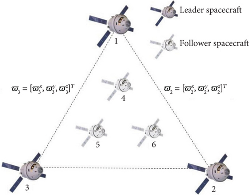
This section considers a spacecraft formation flying system with three Leader Spacecrafts 1, 2, 3 and three Follower Spacecrafts 4, 5, 6. The equation of motion of spacecraft i in the SE (3) is described as (6).
The first leader spacecraft tracks the desired trajectory; other leader spacecrafts are expected to form a formation structure of an equilateral triangle based on the position of the first spacecraft, while the follower spacecrafts are expected to fly inside the equilateral triangle. Moreover, Figure 2 shows the formation structure. In this diagram, ϖ2 and ϖ3 represent the expected relative positions between Spacecrafts 1 and 2 and 1 and 3, respectively.
4.2. Parameter Setting
In this section, the parameters of the spacecraft are shown.
The parameters of the spacecrafts are set as Table 1.
| Parameter | Value |
|---|---|
| m | 0.9 |
| n | 0.3 |
| k1 | 6 |
| k2 | 4 |
| ω21 | [100 0 − 10]T |
| k3 | 8 |
| k4 | 1 |
| k5(2, 3, 4, 5, 6) | 8 |
| k6(2, 3, 4, 5, 6) | 1 |
| ω31 | [0 100 − 10]T |
The selected exponentially decaying functions are set as ρq(t) = (5 − 0.1)e−t + 0.1, ρl(t) = (50 − 1)e−t + 1, ρ2,3(t) = (25 − 1)e−t + 1, ρ4,5(t) = (120 − 1)e−t + 1, and ρ6(t) = (100 − 1)e−t + 1.
The initial attitude and the angular velocity of the spacecraft are set as [0.18π − 0.24π 0.4π]T and [2.5 − 1.5 − 2]T, respectively. The expected attitude and angular velocity are set as [0 0 0]T. The expected position and velocity of the first leader spacecraft are set as pd = [8t 8t 5t + 25sin(t/5)]T and vd = [8 8 5 + 5cos(t/5)]T. The initial value of the spacecrafts is set in Table 2 as [0 0 0]T.
| Conditions | Position (m) | Velocity (m/s) |
|---|---|---|
| Leader 1 | [0 0 5]T | [0 0 0]T |
| Leader 2 | [110 − 10 5]T | [0 0 0]T |
| Leader 3 | [0 110 5]T | [0 0 0]T |
| Follower 4 | [80 80 0]T | [0 0 0]T |
| Follower 5 | [50 − 40 − 5]T | [0 0 0]T |
| Follower 6 | [−40 50 − 5]T | [0 0 0]T |
4.3. Simulation Results
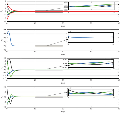
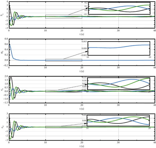
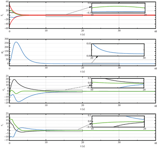
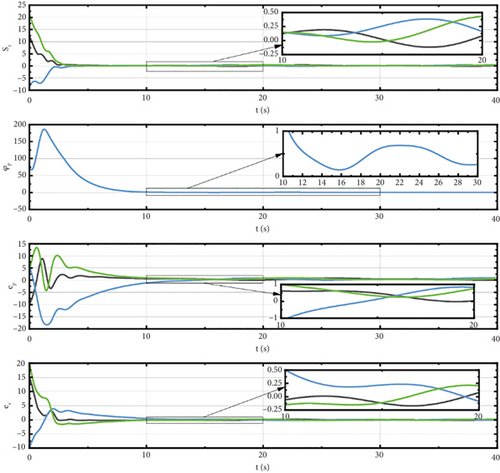
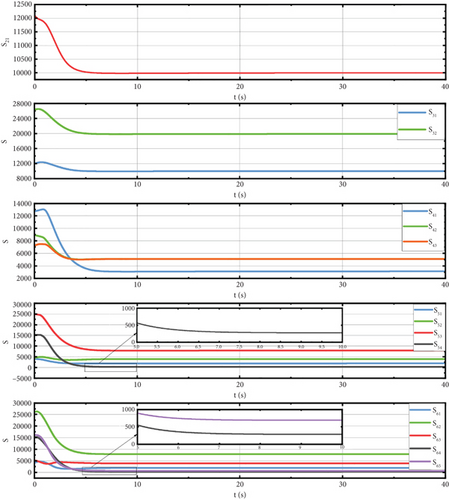
In this section, the simulation results are analyzed in detail. Figure 3 shows the trajectories of the spacecrafts. Figures 4 and 5 illustrate the sliding surface, attitude error, and angular velocity error of the spacecrafts using our method (a) and sliding mode control (SMC) method (b). Figure 6 displays the spatial measurements between any two spacecrafts. Figure 7 presents the errors of the leader spacecrafts. Figure 8 shows the containment error of the follower spacecrafts. Figure 9 shows the constraint-following error under the PPC of spacecraft i.
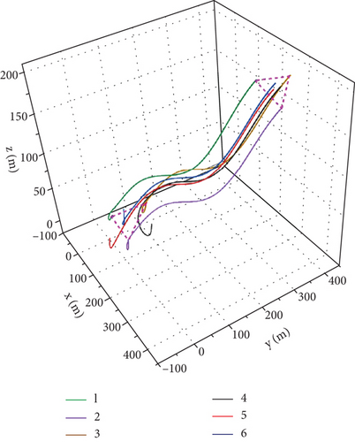


In Figure 3, for a limited time, Leader Spacecrafts 1–3 form the desired triangular formation, and Follower Spacecrafts 4–6 enter the triangular region constructed by the three leader spacecrafts, verifying the leader formation and follower containment performance. Additionally, this figure illustrates that none of the spacecraft trajectories intersect at any time, indicating high effectiveness in collision avoidance.
It can be seen in Figures 4 and 5 the clear trend that the errors in overall attitude, angular velocity, position, and velocity of the first leader spacecraft are converged to around 0 as the variation of the exponentially decaying functions. Compared to the SMC method, our controller can make the error reduction faster and larger, demonstrating higher control accuracy and greater stability.
As shown in Figure 6, the spatial measurements Sih and ΔSih(i, h ∈ {1, 2, 3, 4, 5, 6}, i ≠ 1) are always positive. As demonstrated, the method achieves the expected collision avoidance performance.
Figure 7 shows that the formation errors e21 and e31 converge to around 0 before t = 5 s and remain stable with ς21 ≈ 0.2, ς31 ≈ 0.37. Therefore, the result in this diagram demonstrates that our method can achieve the desired performance of formation.
From Figure 8, we can see that the containment errors e4, e5, and e6 converge to around 0 before t = 5 s and keep stable with ς4 ≈ 0.81, ς5 ≈ 0.49, ς6 ≈ 0.59. Therefore, the paper demonstrates the expected performance of containment. In the simulation, with uncertainties in dΩ and dV, both the dynamics model of spacecraft and the constraints are nonlinear. Therefore, the results shown in Figure 8 indicate that our controller can solve the formation–containment, collision avoidance, uncertainty, and nonlinearity problems.
Looking at Figure 9, it is apparent that all constraint-following errors remain within the range of the prescribed performance function. These errors converge to around zero before t = 4 s. From this result, indicates that our control scheme can achieve containment, formation, and collision avoidance effectively, and its performance function can be applied to the transient and steady-state responses of the system to achieve high-precision control.
5. Conclusions
The present study was designed to determine the effect of spacecraft formation multimission execution problem modeled on the nonlinear manifold SE (3) with prescribed performance. First, for spacecraft attitude trajectory integration, the error vector of each spacecraft is set using the configuration error function on SE (3). Formation containment control is then employed to design formation errors for multiple spacecraft, enabling them to perform formation, collision avoidance, and containment tasks simultaneously. Finally, the prescribed performance control is applied to ensure that the formation error is continuously limited and the convergence rate is higher than expected. The simulation results illustrate the effectiveness of the proposed control scheme for multitask completion and high-precision control. The results indicate that the control scheme not only avoids singularity and the unwinding phenomenon but also ensures that the performance of the spacecraft formation is within the prescribed limits while completing multiple missions.
Ethics Statement
The authors have nothing to report.
Conflicts of Interest
The authors declare no conflicts of interest.
Funding
This research received no external funding.
Open Research
Data Availability Statement
Data will be made available on request.


